CAREL INDUSTRIES HQs
Via dell’Industria, 11 – 35020 Brugine – Padova (Italy)
T
el.
(+39)
0499716611
–
F
ax
(+39)
0499716600
–
e-mail:
[email protected] –
www.carel.comG
G0
2
LAN FIELD
24V~/24V
20VA/9W
L N
230 Vac
24 Vac
IP
GND + –
collegare a terra funzionale /
connect to functional earth
coppia intrecciata
interfaced couple
shield
shield
or
MONTAJ
Operatörlerin veya panoların güvenliğini temin etmek için, herhangi
bir işlem gerçekleştirmeden önce güç bağlantısını kesin. Ürün bir
elektrik panosunun içine kurulmalıdır; eğer pano plastik malzemeden
yapılmışsa 5VA alev alma derecesine sahip olmalıdır.
Yalnızca ambalaj içindeki kapalı mekan antenlerini kullanın.
Eğer ürünün metal bir elektrik panosunun içine monte edilmesi
gerekirse, antenin uzaklaştırılması tavsiye edilir. Metal elektrik panosu
toprak bağlantılı olmalıdır. Bunun için BMBSTEWA00 (Wi-Fi) veya
BMBSTEGA00 (2/4G) uzatmalarını kullanın. Maksimum uzatma bağlantısı
uzunluğu, hem Wİ-Fi hem de 2G/4G için, 3 m’dir.
Anteni uygun bir koruma olmadan herhangi bir atmosferik etkenlere
(yağmur, UV ışınları, vb.) maruz bırakmayın.
Anten insan vücudundan minimum 20 cm mesafeye monte edilmelidir.
Belirtilenden farklı bir güç kaynağı voltajı sisteme ciddi şekilde zarar verir;
İlgili uçbirimler için uygun kablo uçlarını kullanın. Her vidayı gevşetin,
kablo uçlarını sokun ve tekrar vidaları sıkın. İşlem tamamlandığında,
yeterli miktarda sıkıldığını denetlemek için kabloları hafçe çekin.
Cihazı binanın dış hatlarına monte etmeyin.
İLK IŞLEMEYE ALMA PROSEDÜRÜ
Bilgisayar veya tablet aracılığıyla tERA platformuna bağlanın,
“Kongürasyon” menüsüne erişin ve belirtilen prosedürleri takip edin.
Eğer prosedür bunu gerektirirse, ürünün ön
kapağının altında bulunan ürün etiketinin üzerinde
yazan Seri Numarasını ve Güvenlik Kodunu girin.
DİKKAT: yalnızca hattın tüm kontrolleri doğru bir şekilde yapıldıktan
sonra montaj işlemi tamamlanabilir ve tesisattan uzaklaşılabilir.
GEÇİCİ IP ATAMA
Gerçek IP adresinin bilinmediği bir durumda, erişim için Cloudgate LAN
portuna geçici bir IP adresi atamak için aşağıdaki adımları takip edin:
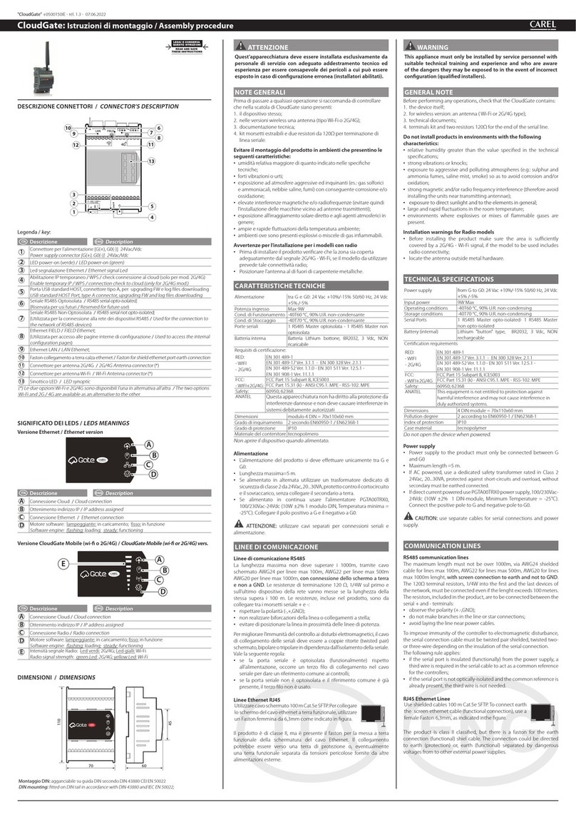
• “Geçici IP düğmesini etkinleştir” (4) düğmesine basın ve 2 saniye
boyunca basılı tutun
• “IP adresi alınıyor”(B) LED alarm lambası yeşil renkte yanıp sönmeye başlar
• CloudGate’e artık yaklaşık 1 saat boyunca 172.16.0.33/16 IP adresinden
erişilebilir, bu sürenin sonunda geçici IP adresi otomatik olarak devre
dışı kalır.
WPS İŞLEVİ (WI-FI MODELLERİ İÇİN)
Cloudgate’i bir internet erişimi olması için, WPS işlevini kullanarak, Wi-Fi
yönlendiricisi ile eşleştirmek için aşağıdaki adımları izleyin:
• “Geçici IP düğmesini etkinleştir” (4) düğmesine basın ve 10 saniye
boyunca basılı tutun
• “Minimum radyo sinyal gücü” (E) LED lambası yeşil renkte yanıp
sönmeye başlar;
• bu noktada yönlendiricide WPS işlevini başlatın;
• Cloudgate yönlendirici ile eşleşir eşleşmez, “IP adresi alınıyor” (B) LED
lambası radyo sinyali yoğunluğu LED lambası (E) ile birlikte yanar.
Not: WPS işlevi yaklaşık 2 dakika boyunca aktif (eşleşme bekliyor)
durumda kalır.
BULUTA BAĞLANTI KONTROLÜ(YALNIZCA 2G/4G
MOD.):
Cihazın buluta doğru şekilde bağlandığını doğrulamak için aşağıdaki
işlemleri takip edin:
• “Geçici IP düğmesini etkinleştir” (4) düğmesine basın ve 10 saniye
boyunca basılı tutun
• “Min. radyo sinyal gücü”(E) LED lambası yeşil renkte yanıp sönmeye başlar;
• Cloudgate yönlendirici ile eşleşir eşleşmez, “IP adresi alınıyor” (B) LED
lambası yanar;
• Bulut ile doğru şekilde bağlantının kurulduğunu onaylamak için
“bulut bağlantısı” (A) ışığının yanması için 1 dakika boyunca bekleyin.
FABRIKA AYARLARINA GERI DÖNDÜRME (FABRI-
KA VERILERINE RESETLEME)
Eğer CloudGate’in varsayılan ayarlara geri döndürülmesi gerekirse
(ilk başlatma, kongürasyonu, geçmiş verileri ve kurulmuş olan tüm
güncellemeleri silme) aşağıdaki işlemler gerçekleştirin:
• Cloudgate güç bağlantısını kesin;
• “Geçici IP düğmesini etkinleştir” (5) düğmesine 5 saniye boyunca
basarak güç verin;
• “SW motor”LED lambası (D) derhal yavaş bir şekilde yanıp sönmeye başlar;
• hızlı yanıp sönmeye başladığı zaman düğmeyi bırakın;
• “SW motor”LED (D) lambası 5 saniye boyunca yanıp sönmeye başlar;
• LED lamba tekrar hızlı bir şekilde yanıp sönmeye başladığında, tekrar
düğmeye basın ve yavaş yanıp sönmesini bekleyin;
• “Fabrika ayarlarına geri döndürme” prosedürü devam etmektedir ve
düğme bırakılabilir ve CloudGate yeniden başlatılabilir.
Not: teknik broşür diğer dillerde mevcuttur ve www.carel.com
internet sitesinden indirilebilir ("Cloudgate/Teknik Broşür bölümünden:
https://www.carel.com/product/cloudgate).
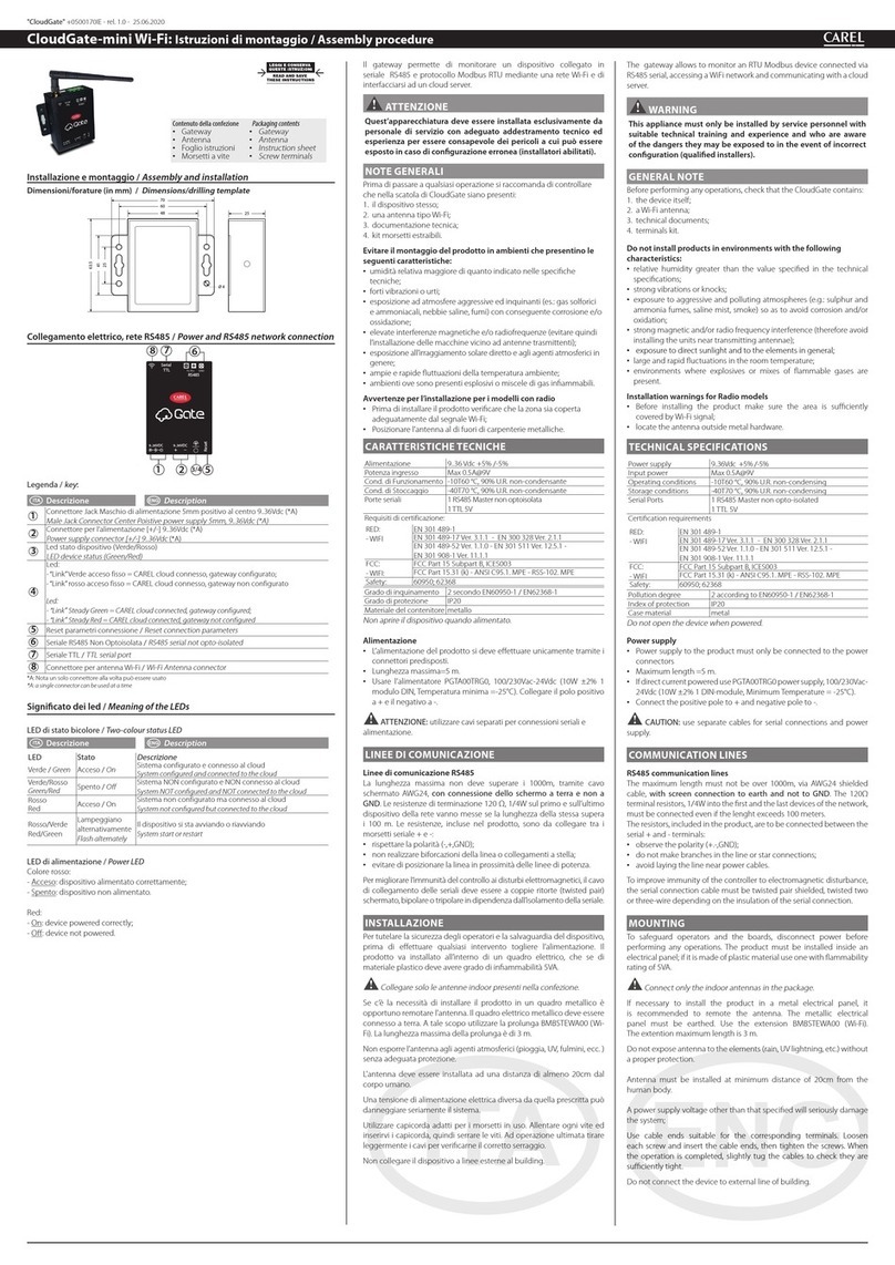
MOUNTING
To safeguard operators and the boards, disconnect power before
performing any operations. The product must be installed inside an
electrical panel; if it is made of plastic material use one with ammability
rating of 5VA.
Connect only the indoor antennas in the package.
If necessary to install the product in a metal electrical panel, it is
recommended to remote the antenna. The metallic electrical panel must
be earthed. Use the extension BMBSTEWA00 (Wi-Fi) or BMBSTEGA00
(2/4G). The extention maximum length is 3 m, for Wi-Fi and 2G/4G.
Not exposure the antenna to the atmospheric agent (rain, UV lightning,
etc.) without a proper protection.
Anyway antennas must be installed at minimum distance of 20cm from
the human body.
A power supply voltage other than that specied will seriously damage
the system;
Use cable ends suitable for the corresponding terminals. Loosen
each screw and insert the cable ends, then tighten the screws. When
the operation is completed, slightly tug the cables to check they are
suciently tight.
Do not connect the device to external line of building.
FIRST COMMISSIONING PROCEDURE
Connect to the tERA platform via PC or tablet, access the“Conguration”
menu and follow the procedure.
If required by procedure, insert the Serial Number
and Security Code indicated on the product label,
placed under the front cover.
ATTENTION: only when all line controllers have been correctly
detected can installation be concluded and the plant be abandoned.
TEMPORARY IP ASSIGNMENT
To assign a temporary IP address to the Cloudgate LAN port for access
when the actual IP is not known, proceed as follows:
• press and hold the“Enable temporary IP button” (4) for 2 seconds
• the a "obtaining IP address" (B) alarm LED - will start ashing green
• CloudGate can now be accessed at IP address 172.16.0.33/16 for
around one hour, after which the temporary IP will be automatically
disabled.
WPS FUNCTION (FOR WI-FI MODELS)
To pair the Cloudgate to router Wi-Fi, using the WPS function, to have an
internet access, proceed as follows:
• press and hold the“Enable temporary IP button” (4) for 10 seconds;
• the "minimum radio signal power" (E) LED will start ashing green;
• now start WPS functionality in the router;
• as soon as CloudGate has been paired to the router, the "obtain IP
address" (B) LED will light up together with the radio signal intensity
LED (E).
Note: the WPS functionality will be active (pending pairing) for about
2 minutes
CONNECTION CHECK TO CLOUD (ONLY MOD.
2G/4G):
To verify the correct connection of the device to the cloud, proceed as
follows:
• press and hold the“Enable temporary IP button” (4) for 10 seconds;
• the "minimum radio signal power" (E) LED will start ashing green;
• as soon as CloudGate has been paired to the router, the "obtain IP
address" (B) LED will light up;
• wait about 1 minute for "cloud connection" (A) lights up to obtain
conrmation of the correct connection to the cloud.
FACTORY RESET (FACTORY DATA RESET)
If it is necessary to reset the CloudGate to the default settings (initial
start-up, deleting the conguration, historical data and any updates
installed), proceed as follows:
• disconnect power from the Cloudgate;
• power on pressIng and holding the “Enable temporary IP button” (5)
for about 5s;
• "SW motor" LED (D) will start ashing slowly;
• when it starts ashing quickly, release the button;
• the "SW motor" LED (D) will start to ash slowly for about 5s;
• when LED re-starts ashing quickly, press the button again and wait
for the slow ashing;
• the "factory reset" procedure is in progress and the key can be
released and CloudGate restarted.
Note: the technical leaet is available in other languages and can
be downloaded from the website www.carel.com (in the section
"Cloudgate/Technical Lefalet: https://www.carel.com/product/
cloudgate).
CAUTION
This equipment has been tested and found to comply with the limits for a Class B digital device, pursuant
to Part 15 of the FCC Rules. These limits are designed to provide reasonable protection against harmful
interference in a residential installation. This equipment generates, uses and can radiate radio frequency
energy and, if not installed and used in accordance with the instructions, may cause harmful interference
to radio communications. However, there is no guarantee that interference will not occur in a particular
installation. If this equipment does cause harmful interference to radio or television reception, which
can be determined by turning the equipment o and on, the user is encouraged to try to correct the
interference by one of the following measures:
• Reorient or relocate the receiving antenna.
• Increase the separation between the equipment and receiver.
• Connect the equipment into an outlet on a circuit dierent from that to which the receiver is
connected.
• Consult the dealer or an experienced radio/TV technician for help.
FCC Caution: Any changes or modications not expressly approved by the party responsible for
compliance could void the user's authority to operate this equipment.
TEMEL UYARILAR /
MAIN WARNINGS
BERTARAF ETME TALIMATLARIL / GUIDELINES FOR DISPOSAL
• Cihaz (veya ürün) ülkede yürürlükte olan atık bertaraf etme mevzuatına uygun bir
şekilde ayrı olarak bertaraf edilmelidir.
• Cihazı belediye atığı olarak bertaraf etmeyin; özel atık bertaraf etme merkezleri
aracılığıyla bertaraf edilmelidir.
• Ürünü bertaraf etmeden önce, ürünün içerisindeki pil verilen talimatlara uygun bir
şekilde çıkartılmalı ve üründen ayrılmalıdır.
• Ürünün uygun olmayan şekilde kullanılması ve hatalı bir şekilde bertaraf edilmesi insan
sağlığı ve çevre üzerinde olumsuz etkiler yaratabilir.
• Elektrik ve elektronik atıkların yasalara aykırı bir şekilde bertaraf edilmesi halinde
uygulanacak yaptırımlar ülkede yürürlükte olan ilgili atık bertaraf etme mevzuatınca
belirlenmiştir.
•
The appliance (or the product) must be disposed of separately in accordance with the
local waste disposal legislation in force.
•
Do not dispose of the product as municipal waste; it must be disposed of through
specialist waste disposal centres.
•
The product contains a battery that must be removed and separated from the rest of
the product according to the instructions provided, before disposing of the product.
•
Improper use or incorrect disposal of the product may negative eects on human
health and on the environment.
•
In the event of illegal disposal of electrical and electronic waste, the penalties are
specied by local waste disposal legislation.
ÖNEMLI UYARI /
IMPORTANT WARNINGS
CAREL ürünü, çalışma şekli ürünle birlikte gelen veya satın almadan önce bile www.carel.
com internet sitesinden indirilebilen teknik belgelerde belirtilen, son teknoloji ürünü bir cihazdır.
- Müşteri (nihai ekipmanı geliştiren, tasarlayan veya kuran), spesik nihai kurulum ve/veya
ekipmandan beklenen sonuçları elde etmek amacıyla ürünün kongürasyonu aşamasına ilişkin
tüm sorumlulukları ve riskleri üstlenir. Kullanıcı kılavuzunda belirtilen/talep edilen bu çalışma
fazının eksikliği nihai ürünün hatalı işlemesine neden olabilir, bu durumdan CAREL sorumlu
tutulamaz. Nihai müşteri ürünü, yalnızca ürünün kendisine ilişkin belgelerde açıklandığı şekilde
kullanmalıdır. CAREL’in kendi ürününe ilişkin yükümlülüğü, www.carel.com internet sitesinde
bulunan CAREL genel sözleşme şartları ve/veya müşterileri ile yaptığı özel anlaşmalar tarafından
belirlenir.
The CAREL product is a state-of-the-art product, whose operation is specied in the technical
documentation supplied with the product or can be downloaded, even prior to purchase, from
the website www.carel.com. - The client (builder, developer or installer of the nal equipment)
assumes every responsibility and risk relating to the phase of conguration the product in order to
reach the expected results in relation to the specic nal installation and/or equipment. The lack of
such phase of study, which is requested/indicated in the user manual, can cause the nal product
to malfunction of which CAREL can not be held responsible. The nal client must use the product
only in the manner described in the documentation related to the product itself. The liability of
CAREL in relation to its own product is regulated by CAREL’s general contract conditions edited on
the website www.carel.com and/or by specic agreements with clients.
BAĞLANTI ŞEMASI /
CONNECTIONS DRAWING
DESTEK
SUPPORT
Cihazın hatalı çalışması durumunda
CAREL destek personeli ile iletişime geçin.
Her türlü soru veya şüpheniz için, lütfen
In case of device malfunctions contact
CAREL support personnel. For any
questions or concerns, please contact
"CloudGate" +0500150TR - rel. 1.1 - 20.10.2020
This device complies with Part 15 of the FCC Rules. Operation is subject to the following two conditions:
(1) this device may not cause harmful interference, and
(2) this device must accept any interference received, including interference that may cause undesired
operation.
FCC RF Radiation Exposure Statement:
1. This Transmitter must not be co-located or operating in conjunction with any other antenna or
transmitter.
2. This equipment complies with FCC RF radiation exposure limits set forth for an uncontrolled
environment. This equipment should be installed and operated with a minimum distance of 20
centimeters between the radiator and your body.
CAUTION
1. “CAUTION” Risk of explosion if the battery is replaced by an incorrect type or short circuit;
2. Never open the equipment. For safety reasons, the equipment should be opened only by qualied
skilled person;
3. can only be safely used lower than 2000 meters altitude


