manuals.online logo
Brands
  1. Home
  2. •
  3. Brands
  4. •
  5. Carel
  6. •
  7. Gateway
  8. •
  9. Carel CloudGate Manual

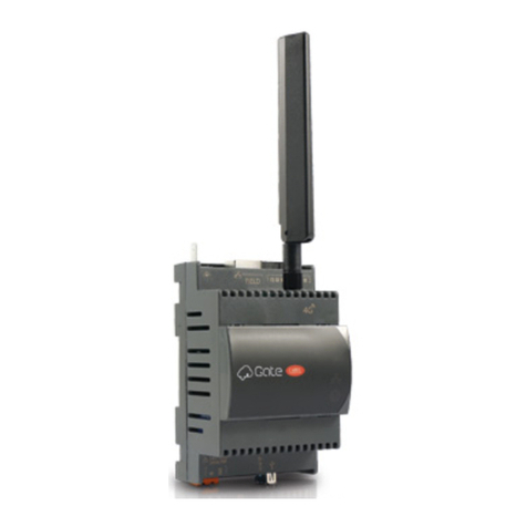
Carel CloudGate Manual

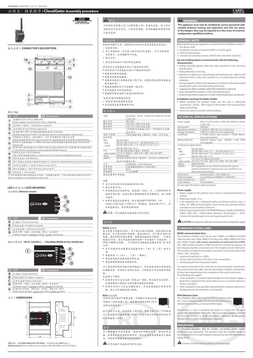
ОПИСАНИЕ РАЗЪЕМОВ /
CONNECTOR’S DESCRIPTION
G
G0
2
24V~/24V
20VA/9W
LAN FIELD 6
7
9
11
13
8
1
10
12
4
25
3
Обозначения /
Key
:
Описание
Description
1
Разъем питания [G(+), G0(-)] 24В~/= /
Power supply connector [G(+), G0(-)] 24Vac/Vdc
2
Зеленый светодиод питания /
LED power-on (green)
3
Светодиод Ethernet /
Ethernet signal Led
4
Кнопка временного IP-адреса / WPS / соединения с облаком (только в модели
2G/4G.) /
Enable temporary IP / WPS / connection check to cloud (only for 2G/4G mod.)
5
Стандартный порт USB HOST типа A, обновление микропрограммного обеспечения
и скачивание файлов журналов /
USB standard HOST Port, type A connector,
upgrading FW and log files downloading
6
Оптоизолированный последовательный порт RS485 /
RS485 serial opto-isolated;
(Зарезервировано для использования в будущем / R
eserved for future use
)
7
Последовательный порт RS485 без оптоизоляции /
RS485 serial not opto-isolated
;
(Используется для подключения к сети устройств RS485 /
Used for the connection to
the network of RS485 devices
)
8
FIELD Ethernet /
FIELD Ethernet
; (Используется для доступа к внутренним страницам
конфигурации /
Used to access the internal configuration pages
)
9
Сеть Ethernet /
LAN Ethernet
;
10
Клемма заземления экрана кабеля порта Ethernet /
Faston for shield ethernet port earth connection
11
Антенный разъем 2G/4G /
2G/4G Antenna connector
(*)
12
Антенный разъем Wi-Fi /
Wi-Fi Antenna connector
(*)
13
Светодиод /
LED synoptic
(*) Есть два варианта: Wi-Fi и 2G / 4G / The two options Wi-Fi and 2G / 4G are available as an
alternative to the other
ОПИСАНИЕ СВЕТОДИОДОВ /
LEDS MEANINGS
Версия Ethernet /
Ethernet version
IP
A
C
D
B
Описание
Description
A
Подключение к облаку /
Cloud connection
B
IP-адрес выдан /
IP address assigned
C
Соединение Ethernet /
Ethernet connection
D
Программное обеспечение: мигает: загрузка; горит: работает
Software engine: flashing: loading; steady: functioning
Модель CloudGate Mobile (wi- или 2G/4G)
/
CloudGate Mobile (wi- or 2G/4G) vers.
A
C
D
B
E
Описание
Description
A
Подключение к облаку /
Cloud connection
B
IP-адрес выдан /
IP address assigned
C
Беспроводная сеть /
Radio connection
D
Программное обеспечение: мигает: загрузка; горит: работает
Software engine: flashing: loading; steady: functioning
E
Сила беспроводного сигнала: зеленый светодиод: 2G/4G; желтый светодиод: Wi-Fi
Radio signal strength: green Led: 2G/4G; yellow Led: Wi-Fi
ГАБАРИТЫ /
DIMENSIONS
70 60
110
45
IP
Монтаж на DIN-рейку: по стандартам DIN 43880 и IEC EN 50022
DIN mounting: tted on DIN rail in accordance with DIN 43880 and IEC EN 50022
"CloudGate" +0500150RU - rel. 1.2 - 24.09.2021
CloudGate: Инструкции по монтажу / Assembly procedure
ОСТОРОЖНО
Данное устройство разрешается устанавливать только
сервисному персоналу с соответствующей технической
подготовкой, опытом и знаниями рисков, которым они
могут подвергаться в случае неправильной настройки
(квалифицированные установщики).
ОБЩЕЕ УКАЗАНИЕ
В первую очередь проверьте комплектность поставки системы
диспетчерского управления CloudGate:
1. Данное устройство;
2. У беспроводной модели есть антенна (типа Wi-Fi или 2G/4G);
3. Техническая документация;
4. Комплект клемм и два согласующих резистора 120 Ом
Запрещается устанавливать устройство в следующих местах:
• относительная влажность воздуха выше значения, указанного в
технических характеристиках;
• сильная вибрация или удары;
• наличие агрессивных газов и примесей (например, пары серы
и аммиака, соляной туман, дым), способных стать причиной
коррозии и/или окисления;
• сильные электромагнитные и/или радиочастотные помехи (не
устанавливайте рядом с передающей антенной);
• прямые солнечные лучи и осадки;
• значительные и резкие колебания температуры воздуха:
• взрывоопасные газы или пожароопасные смеси.
Предупреждения при установке моделей с радиочастотными
модулями
• Перед установкой устройства с беспроводной передачей данных
следует убедиться, что уровень сигнала 2G/4G - Wi-Fi достаточно
сильный;
• Расположите антенну на некотором удалении от металлических
устройств.
ТЕХНИЧЕСКИЕ ХАРАКТЕРИСТИКИ
Питание G и G0: 24 В перем. тока +10%/-15% 50/60 Гц, 24 В
пост. тока +5% /-5%
Мощность потребления 9 Вт макс.
Условия работы от -40 до 60 °C, <90% отн. влажности без конденсата
Условия хранения от -40 до 70 °C, <90% отн. влажности без конденсата
Последовательные порты 1 оптоизолированный порт RS485 для ведущего
устройства, 1 порт RS485 для ведущего устройства
без оптоизоляции
Батарея (встроенная) Литиевая батарейка типа «кнопка», BR2032, 3 В пост.
тока, (не аккумулятор)
Сертификационные требования
RED:
- WIFI
- 2G/4G
EN 301 489-1
EN 301 489-17 вер. 3.1.1 - EN 300 328 вер. 2.1.1
EN 301 489-52 вер. 1.1.0 - EN 301 511 вер. 12.5.1 -
EN 301 908-1 вер. 11.1.1
Федеральная
комиссия по
связи США:
- WIFI+2G/4G
Федеральная комиссия по связи США, часть 15 подраздел
B, ICES003
Федеральная комиссия по связи США, часть 15.31 (k); ANSI
C95.1. MPE - RSS-102. MPE
Безопасность: 60950; 62368
ANATEL Данное устройство не имеет защиту от помех и само не
может являться причиной помех при условии применения в
составе рекомендованных систем.
Размеры занимает место 4 модулей на DIN-рейке =
70x110x60 мм
Класс загрязнения 2 по стандарту EN60950-1 / EN62368-1
Класс защиты IP10
Материал корпуса технополимер
Запрещается открывать корпус устройства под напряжением.
Питание
• Питающее напряжение к устройству подводится на клеммы G и G0.
• Максимальная длина = 5 м.
• При питании от сети переменного тока рекомендуется использовать
специальный разделительный трансформатор класса 2 на 24 В
переменного тока, 20 ... 30 ВА, с защитой от короткого замыкания и
перегрузкии без заземления вторичной обмотки.
• Для питания постоянным током рекомендуется использовать
блок питания PGTA00TRX0, 100 / 230В перем. тока -24В пост. тока
(10Вт ± 2%, занимает место 1 модуль на DIN-рейке, минимальная
температура минус 25 °C). Плюсовая клемма подсоединяется к
клемма G, а минусовая к клемме G0.
ВНИМАНИЕ: последовательные цепи и цепи питания
подсоединяются отдельными кабелями.
ПЕРЕДАЧА ДАННЫХ
Порты RS485
Максимальная длина экранированного кабеля сечением AWG24
не может превышать 1000 м, AWG22 для линий макс. 500 м, AWG20
для линий макс. длиной 1000 м. Экран кабеля заземляется (не к
клемме GND). Согласующие сопротивления 120 Ом, 1/4 Вт включаются
на первом и последнем устройствах сети, даже если дистанция более
100 метров.
Входящие в комплект сопротивления подсоединяются к
последовательным клеммам + и -:
• необходимо соблюдать полярность (+.-,GND);
• при соединение звездой и шлейфом запрещается делать ответвления;
• запрещается прокладывать кабель последовательного
соединения вблизи кабелей питания.
В целях повышения защищенности контроллера от электромагнитных
помех, в качестве кабеля последовательного интерфейса в
зависимости от изоляции последовательного порта применяется
2-проводная или 3-проводная экранированная витая пара.
Необходимо соблюдать следующие правила:
• Если последовательный порт функционально изолирован от цепи
питания, в кабеле последовательного интерфейса должна быть
третья жила, которая будет служить общим проводом контроллеров.
• Если у последовательного порта нет оптоизоляции, а общий
провод уже есть, третья жила в кабеле не нужна.
Порт Ethernet с разъемом RJ45
Подсоединяется экранированным кабелем SFTP
длиной до 100 м категории 5e. Для заземления экрана
кабеля Ethernet (функциональное соединение)
используется гнездовой разъем Faston 6,3 мм, как
показано на рисунке.
Устройство относится к классу II, но для заземления
(функционального) экрана кабеля имеется разъем Faston.
Соединение с землей (защитной) или заземлением
(функциональным) отделяется от высоких напряжений других
внешних источников питания.
WARNING
This appliance must only be installed by service personnel with
suitable technical training and experience and who are aware
of the dangers they may be exposed to in the event of incorrect
conguration (qualied installers).
GENERAL NOTE
Before performing any operations, check that the CloudGate contains:
1. the device itself;
2. for wireless version: an antenna ( Wi-Fi or 2G/4G type);
3. technical documents;
4. terminals kit and two resistors 120 for the end of the serial line.
Do not install products in environments with the following
characteristics:
• relative humidity greater than the value specied in the technical
specications;
• strong vibrations or knocks;
• exposure to aggressive and polluting atmospheres (e.g.: sulphur and
ammonia fumes, saline mist, smoke) so as to avoid corrosion and/or
oxidation;
• strong magnetic and/or radio frequency interference (therefore avoid
installing the units near transmitting antennae);
• exposure to direct sunlight and to the elements in general;
• large and rapid uctuations in the room temperature;
• environments where explosives or mixes of ammable gases are
present.
Installation warnings for Radio models
• Before installing the product make sure the area is suciently
covered by a 2G/4G - Wi-Fi signal, if the model to be used includes
radio connectivity;
• locate the antenna outside metal hardware.
TECHNICAL SPECIFICATIONS
Power supply from G to G0: 24 Vac +10%/-15% 50/60 Hz, 24 Vdc
+5% /-5%
Input power 9W Max
Operating conditions -40T60 °C, 90% U.R. non-condensing
Storage conditions -40T70 °C, 90% U.R. non-condensing
Serial Ports 1 RS485 Master opto-isolated- 1 RS485 Master
non opto-isolated
Battery (internal) Lithium “button” type, BR2032, 3 Vdc, NON
rechargeable
Certication requirements
RED:
- WIFI
- 2G/4G
EN 301 489-1
EN 301 489-17 Ver. 3.1.1 - EN 300 328 Ver. 2.1.1
EN 301 489-52 Ver. 1.1.0 - EN 301 511 Ver. 12.5.1 -
EN 301 908-1 Ver. 11.1.1
FCC:
- WIFI+2G/4G
FCC Part 15 Subpart B, ICES003
FCC Part 15.31 (k)- ANSI C95.1. MPE - RSS-102. MPE
Safety: 60950; 62368
ANATEL This equipment is not entitled to protection against
harmful interference and may not cause interference in
duly authorized systems.
Dimensions 4 DIN module = 70x110x60 mm
Pollution degree 2 according to EN60950-1 / EN62368-1
Index of protection IP10
Case material tecnopolymer
Do not open the device when powered.
Power supply
• Power supply to the product must only be connected between G
and G0
• Maximum length =5 m.
• If AC powered, use a dedicated safety transformer rated in Class 2
24Vac, 20...30VA, protected against short-circuits and overload, without
secondary must be earthed connected.
• If direct current powered use PGTA00TRX0 power supply, 100/230Vac-
24Vdc (10W ±2% 1 DIN-module, Minimum Temperature = -25°C).
Connect the positive pole to G and negative pole to G0.
CAUTION: use separate cables for serial connections and power
supply.
COMMUNICATION LINES
RS485 communication lines
The maximum length must not be over 1000m, via AWG24 shielded
cable for lines max 100m, AWG22 for lines max 500m, AWG20 for lines
max 1000m lenght, with screen connection to earth and not to GND.
The 120Ω terminal resistors, 1/4W into the rst and the last devices of
the network, must be connected even if the lenght exceeds 100 meters.
The resistors, included in the product, are to be connected between the
serial + and - terminals:
• observe the polarity (+.-,GND);
• do not make branches in the line or star connections;
• avoid laying the line near power cables.
To improve immunity of the controller to electromagnetic disturbance,
the serial connection cable must be twisted pair shielded, twisted two-
or three-wire depending on the insulation of the serial connection.
The following rule applies:
• if the serial port is insulated (functionally) from the power supply, a
third wire is required in the serial cable to act as a common reference
for the controllers;
• if the serial port is not optically-isolated and the common reference is
already present, the third wire is not needed.
RJ45 Ethernet Linee
Use shielded cables 100 m Cat.5e SFTP. To connect earth
the screen ethernet cable (functional connection), use a
female Faston 6,3mm, as indicated inthe gure.
The product is class II classied, but there is a faston for the earth
connection (functional) shiel cable. The connection could be directed
to earth (protection) or, earth (functional) separated by dangerous
voltages from to other external power supplies.
CAREL INDUSTRIES HQs
Via dell’Industria, 11 – 35020 Brugine – Padova (Italy)
Tel. (+39) 0499716611 – Fax (+39) 0499716600 – e-mail: [email protected] – www.carel.com
МОНТАЖ
Для защиты плат и собственной безопасности перед любыми
работами необходимо отключать устройство от электропитания.
Устройство устанавливается внутри электрошкафа. Если он из
пластика, то должен иметь класс воспламеняемости 5 ВА.
Разрешается подсоединять только антенны для помещений из
комплекта.
При необходимости установки устройства в металлический шкаф,
антенны рекомендуется выносить снаружи него. Металлический
шкаф должен быть заземлен. Подойдут модели BMBSTEWA00 (Wi-Fi)
или BMBSTEGA00 (2/4G). Длина удлинительного кабеля до 3 м для
моделей Wi-Fi и 2G/4G.
Запрещается подвергать антенну воздействию атмосферных осадков
(дождя, ультрафиолета, молнии и т. д.) без надлежащей защиты.
В любом случае антенны должны находиться на расстоянии не
менее 20 см от тела человека.
Попытка подсоединения к источнику питания с отличным от
указанного напряжением может серьезно повредить устройство.
Следует использовать наконечники кабелей, подходящие к
соответствующим зажимам. Ослабить винт, вставить наконечник
кабеля и затянуть винт. По завершении операции слегка потяните
кабель, чтобы убедиться в прочности соединения.
Запрещается подсоединять устройство к внешней линии здания.
ПОРЯДОК ВВОДА В ЭКСПЛУАТАЦИЮ
Подключитесь к платформе tERA с компьютера или планшета,
откройте меню“Conguration” и следуйте указаниям.
Если потребуется, введите серийный номер
и код безопасности, указанные на табличке
устройства под передней крышкой.
ВНИМАНИЕ: установка считается завершенной, а устройство
готовым к работе только после обнаружения всех линейных
контроллеров.
НАЗНАЧЕНИЕ ВРЕМЕННОГО IPАДРЕСА
Порядок выдачи временного IP-адреса сетевому порту устройства
Cloudgate когда текущий IP-адрес неизвестен:
• нажмите и держите кнопку“Временный IP-адрес”(4) 2 секунды;
• светодиод "получения IP-адреса" (B) - начинает мигать зеленым;
• теперь к устройству CloudGate можно получить доступ в течение
часа по адресу 172.16.0.33/16. По истечении этого времени
данный временный адрес автоматически удаляется.
ФУНКЦИЯ WPS ДЛЯ МОДЕЛЕЙ С WIFI
Для подключения устройства Cloudgate к маршрутизатору Wi-Fi при
помощи функции WPS для выхода в internet:
• нажмите и держите кнопку“Временный IP-адрес”(4) 10 секунд;
• светодиод "минимальный уровень беспроводного сигнала" (E)
начинает мигать зеленым;
• теперь включите функцию WPS в маршрутизаторе;
• когда устройство CloudGate подключится к маршрутизатору,
светодиод "получения IP-адреса " (B) загорится вместе со
светодиодом уровня сигнала (E).
Примечание:функция WPS включается (ожидание
подключения) примерно на 2 минуты
ПРОВЕРКА СОЕДИНЕНИЯ С ОБЛАКОМ ТОЛЬКО
В МОДЕЛИ 2G/4G:
Чтобы проверить правильность подключения устройства к облаку:
• нажмите и держите кнопку“Временный IP-адрес”(4) 10 секунд
• светодиод "минимальный уровень беспроводного сигнала" (E)
начинает мигать зеленым;
• когда устройство CloudGate подключится к маршрутизатору,
светодиод "получения IP-адреса " (B) загорится.
• подождите примерно 1 минуту, чтобы загорелся светодиод
"соединения с облаком" (A), подтверждающий, что соединение в
порядке
ЗАГРУЗКА ЗАВОДСКИХ НАСТРОЕК СБРОС
Если необходимо загрузить заводские настройки устройства
CloudGate (первое включение, удалена конфигурация,
статистические данные и или после установки обновления),
выполните следующие действия:
• отключите питание устройства Cloudgate;
• включите питание, нажав и удерживая кнопку «Временный IP-
адрес» (5) около 5 секунд;
• Светодиод "SW motor" (D) начнет медленно мигать;
• когда он начнет быстро мигать, отпустите кнопку;
• светодиод "SW motor" (D) начнет медленно мигать примерно 5
секунд;
• когда светодиод «SW мотор» начнет быстро мигать, нажмите
кнопку еще раз и удерживайте ее, пока светодиод не перестанет
мигать;
• начинается процедура загрузки заводских настроек и можно
отпустить кнопку, устройство CloudGate перезагрузится.
Примечание: версию данного технического руководства на
другом языке можно скачать на сайте www.carel.com (в разделе
«Cloudgate / Technical Lefalet: https://www.carel.com/product/cloudgate).
MOUNTING
To safeguard operators and the boards, disconnect power before
performing any operations. The product must be installed inside an
electrical panel; if it is made of plastic material use one with ammability
rating of 5VA.
Connect only the indoor antennas in the package.
If necessary to install the product in a metal electrical panel, it is
recommended to remote the antenna.The metallic electrical panel must
be earthed. Use the extension BMBSTEWA00 (Wi-Fi) or BMBSTEGA00
(2/4G). The extention maximum length is 3 m, for Wi-Fi and 2G/4G.
Not exposure the antenna to the atmospheric agent (rain, UV lightning,
etc.) without a proper protection.
Anyway antennas must be installed at minimum distance of 20cm from
the human body.
A power supply voltage other than that specied will seriously damage
the system;
Use cable ends suitable for the corresponding terminals. Loosen
each screw and insert the cable ends, then tighten the screws. When
the operation is completed, slightly tug the cables to check they are
suciently tight.
Do not connect the device to external line of building.
FIRST COMMISSIONING PROCEDURE
Connect to the tERA platform via PC or tablet, access the“Conguration”
menu and follow the procedure.
If required by procedure, insert the Serial Number
and Security Code indicated on the product label,
placed under the front cover.
ATTENTION: only when all line controllers have been correctly
detected can installation be concluded and the plant be abandoned.
TEMPORARY IP ASSIGNMENT
To assign a temporary IP address to the Cloudgate LAN port for access
when the actual IP is not known, proceed as follows:
• press and hold the “Enable temporary IP button” (4) for 2 seconds
• the a "obtaining IP address" (B) alarm LED - will start ashing green
• CloudGate can now be accessed at IP address 172.16.0.33/16 for
around one hour, after which the temporary IP will be automatically
disabled.
WPS FUNCTION FOR WIFI MODELS
To pair the Cloudgate to router Wi-Fi, using the WPS function, to have an
internet access, proceed as follows:
• press and hold the “Enable temporary IP button” (4) for 10 seconds;
• the "minimum radio signal power" (E) LED will start ashing green;
• now start WPS functionality in the router;
• as soon as CloudGate has been paired to the router, the "obtain IP
address" (B) LED will light up together with the radio signal intensity
LED (E).
Note: the WPS functionality will be active (pending pairing) for
about 2 minutes
CONNECTION CHECK TO CLOUD ONLY MOD.
2G/4G:
To verify the correct connection of the device to the cloud, proceed as
follows:
• press and hold the “Enable temporary IP button” (4) for 10 seconds;
• the "minimum radio signal power" (E) LED will start ashing green;
• as soon as CloudGate has been paired to the router, the "obtain IP
address" (B) LED will light up;
• wait about 1 minute for "cloud connection" (A) lights up to obtain
conrmation of the correct connection to the cloud.
FACTORY RESET FACTORY DATA RESET
If it is necessary to reset the CloudGate to the default settings (initial
start-up, deleting the conguration, historical data and any updates
installed), proceed as follows:
• disconnect power from the Cloudgate;
• power on pressIng and holding the “Enable temporary IP button” (5)
for about 5s;
• "SW motor" LED (D) will start ashing slowly;
• when it starts ashing quickly, release the button;
• the "SW motor" LED (D) will start to ash slowly for about 5s;
• when the "SW motor" LED starts ashing quickly, press the button
again and keep it pressed until the LED stops ashing;
• the "factory reset" procedure is in progress and the key can be
released and CloudGate restarted.
Note: the technical leaet is available in other languages and can
be downloaded from the website www.carel.com (in the section
"Cloudgate/Technical Lefalet: https://www.carel.com/product/
cloudgate).
CAUTION
This equipment has been tested and found to comply with the limits for a Class B digital device, pursuant
to Part 15 of the FCC Rules. These limits are designed to provide reasonable protection against harmful
interference in a residential installation. This equipment generates, uses and can radiate radio frequency
energy and, if not installed and used in accordance with the instructions, may cause harmful interference
to radio communications. However, there is no guarantee that interference will not occur in a particular
installation. If this equipment does cause harmful interference to radio or television reception, which
can be determined by turning the equipment o and on, the user is encouraged to try to correct the
interference by one of the following measures:
• Reorient or relocate the receiving antenna.
• Increase the separation between the equipment and receiver.
• Connect the equipment into an outlet on a circuit dierent from that to which the receiver is
connected.
• Consult the dealer or an experienced radio/TV technician for help.
FCC Caution: Any changes or modications not expressly approved by the party responsible for
compliance could void the user's authority to operate this equipment.
ПРЕДУПРЕЖДЕНИЯ /
MAIN WARNINGS
УКАЗАНИЯ ПО УТИЛИЗАЦИИ / GUIDELINES FOR DISPOSAL
• Изделие утилизируется отдельно в соответствии с местными нормативами по
утилизации отходов.
• Запрещается выбрасывать изделие в обычные мусорные бачки; обращайтесь в
специализированные центры утилизации.
• Изделие содержит батарею, которую необходимо снять и утилизировать отдельно
по соответствующим инструкциям перед утилизацией изделия.
• Неправильная эксплуатация или утилизация изделия может нанести вред
здоровью людей и окружающей среде;
• Наказание за незаконную утилизацию отходов производства электрических и
электронных изделий устанавливается государственными органами надзора за
ликвидацией отходов.
•
The appliance (or the product) must be disposed of separately in accordance with the
local waste disposal legislation in force.
•
Do not dispose of the product as municipal waste; it must be disposed of through
specialist waste disposal centres.
•
The product contains a battery that must be removed and separated from the rest of
the product according to the instructions provided, before disposing of the product.
•
Improper use or incorrect disposal of the product may negative eects on human
health and on the environment.
•
In the event of illegal disposal of electrical and electronic waste, the penalties are
specied by local waste disposal legislation.
ВАЖНО /
IMPORTANT WARNINGS
Продукция компании CAREL разрабатывается по современным технологиям,
и все подробности работы и технические описания приведены в эксплуатационной
документации, прилагающейся к каждому изделию. Кроме этого, технические описания
продукции опубликованы на сайте www.carel.com. Вся ответственность и риски при
изменении конфигурации оборудования и адаптации для соответствия конечным
требованиям Заказчика полностью ложатся на самого Заказчика (производителя,
разработчика или наладчика конечной системы). Несоблюдение данного требования
и указаний, приведенных в технических руководствах, может привести к порче
оборудования, и компания CAREL не несет ответственности за подобные поломки.
Эксплуатация оборудования осуществляется только по назначению и в соответствии
с правилами, изложенными в технической документации. Степень ответственности
компании CAREL в отношении собственных изделий регулируется общими положениями
договора CAREL, представленного на сайте www.carel.com, и/или дополнительными
соглашениями, заключенными с заказчиками.
The CAREL product is a state-of-the-art product, whose operation is specied in the technical
documentation supplied with the product or can be downloaded, even prior to purchase, from
the website www.carel.com. - The client (builder, developer or installer of the nal equipment)
assumes every responsibility and risk relating to the phase of conguration the product in order to
reach the expected results in relation to the specic nal installation and/or equipment. The lack of
such phase of study, which is requested/indicated in the user manual, can cause the nal product
to malfunction of which CAREL can not be held responsible. The nal client must use the product
only in the manner described in the documentation related to the product itself. The liability of
CAREL in relation to its own product is regulated by CAREL’s general contract conditions edited on
the website www.carel.com and/or by specic agreements with clients.
СХЕМЫ СОЕДИНЕНИЙ /
CONNECTIONS DRAWING
ПОДДЕРЖКА
SUPPORT
In caso di malfunzionamenti del dispositivo
contattare personale di supporto CAREL.
Per ogni dubbio o segnalazione rivolgersi a
sw[email protected]
In case of device malfunctions contact
CAREL support personnel. For any
questions or concerns, please contact
sw[email protected]
"CloudGate" +0500150RU - rel. 1.2 - 24.09.2021
This device complies with Part 15 of the FCC Rules. Operation is subject to the following two conditions:
(1) this device may not cause harmful interference, and
(2) this device must accept any interference received, including interference that may cause undesired
operation.
FCC RF Radiation Exposure Statement:
1. This Transmitter must not be co-located or operating in conjunction with any other antenna or
transmitter.
2. This equipment complies with FCC RF radiation exposure limits set forth for an uncontrolled
environment. This equipment should be installed and operated with a minimum distance of 20
centimeters between the radiator and your body.
CAUTION
1. “CAUTION” Risk of explosion if the battery is replaced by an incorrect type or short circuit;
2. Never open the equipment. For safety reasons, the equipment should be opened only by qualied
skilled person;
3. can only be safely used lower than 2000 meters altitude
G
G0
2
LAN FIELD
24V~/24V
20VA/9W
LN
230 Vac
24 Vac
IP
GND +–
collegare a terra funzionale /
connect to functional earth
coppia intrecciata
interfaced couple
shield
shield
24 V
dc
or

Other manuals for CloudGate

9

This manual suits for next models

1

Other Carel Gateway manuals

Carel CloudGate-mini Wi-Fi Manual

Carel

Carel CloudGate-mini Wi-Fi Manual

Carel CloudGate Manual

Carel

Carel CloudGate Manual

Carel GATEWAYBN0 User manual

Carel

Carel GATEWAYBN0 User manual

Carel CloudGate User manual

Carel

Carel CloudGate User manual

Carel CloudGate Manual

Carel

Carel CloudGate Manual

Carel CloudGate Manual

Carel

Carel CloudGate Manual

Carel CloudGate-mini Wi-Fi Manual

Carel

Carel CloudGate-mini Wi-Fi Manual

Carel CloudGate Manual

Carel

Carel CloudGate Manual

Carel CloudGate Manual

Carel

Carel CloudGate Manual

Carel CloudGate User manual

Carel

Carel CloudGate User manual

Carel GTW 0BT0 Series User manual

Carel

Carel GTW 0BT0 Series User manual

Carel WEB-GATE WEBG0000B0 User manual

Carel

Carel WEB-GATE WEBG0000B0 User manual

Carel CloudGate Manual

Carel

Carel CloudGate Manual

Popular Gateway manuals by other brands

RTA 460MSBC-NNA4 Product user guide

RTA

RTA 460MSBC-NNA4 Product user guide

RTA 460ESUSB-N70U Product user guide

RTA

RTA 460ESUSB-N70U Product user guide

RTA 460MCBS-N2E Product user guide

RTA

RTA 460MCBS-N2E Product user guide

RTA 460ESUS-NNA4 Product user guide

RTA

RTA 460ESUS-NNA4 Product user guide

Synway SBC Series user manual

Synway

Synway SBC Series user manual

WELLTECH 3502 - RELEASE NOTE V114 release note

WELLTECH

WELLTECH 3502 - RELEASE NOTE V114 release note

Dragino LG01N user manual

Dragino

Dragino LG01N user manual

Atlas Zone Controller Pro ZCM-V2 Install Sheet

Atlas

Atlas Zone Controller Pro ZCM-V2 Install Sheet

M-system R7G-SC-SHL instruction manual

M-system

M-system R7G-SC-SHL instruction manual

Ositech comm Titan II user manual

Ositech comm

Ositech comm Titan II user manual

ZyXEL Communications ZYWALL  20W - datasheet

ZyXEL Communications

ZyXEL Communications ZYWALL 20W - datasheet

RV Tech LORATECH quick start guide

RV Tech

RV Tech LORATECH quick start guide

Allied Telesis RG6x4 Series datasheet

Allied Telesis

Allied Telesis RG6x4 Series datasheet

NetComm HS800 user guide

NetComm

NetComm HS800 user guide

Nomadix AG5800 user guide

Nomadix

Nomadix AG5800 user guide

Permasense GT200-G technical information

Permasense

Permasense GT200-G technical information

ZyXEL Communications P-793H 601156 quick start guide

ZyXEL Communications

ZyXEL Communications P-793H 601156 quick start guide

Anybus AB7702 installation guide

Anybus

Anybus AB7702 installation guide

manuals.online logo
manuals.online logoBrands
  • About & Mission
  • Contact us
  • Privacy Policy
  • Terms and Conditions

Copyright 2025 Manuals.Online. All Rights Reserved.