CAREL INDUSTRIES HQs
Via dell’Industria, 11 – 35020 Brugine – Padova (Italy)
T
el.
(+39)
0499716611
–
F
ax
(+39)
0499716600
–
e
-mail:
[email protected] –
www.carel.comG
G0
2
LAN FIELD
24V~/24V
20VA/9W
LN
230 Vac
24 Vac
IP
GND +–
collegare a terra funzionale /
connect to functional earth
coppia intrecciata
interfaced couple
shield
shield
24 V
or
㧈⺜㿉䄋ㅌⶤ⥛㠘➓䓑䊻㆑㭕㞅⮈⟆㩰ㅉ䅊ㅌ㳍㼀䄧㋋᱄
㆑㭕㞅⮈⟆⡹㿌ㅴ⭹᱄㬚䇤ゴ⧅㼀BMBSTEWA00Wi-Fi⼮〓
BMBSTEGA002G/4G᱄ⰵ䇻Wi-Fi⼮2G/4G䔏⫔ゴ⧅㼀⧅Ⱙ㸋3
㗸᱄
㧈⺜㗜䇱㬫⭒⭥⡄⿅㚨㗕㤌㹑ㅌ㳍㼀⡊㔗䇻⫔㡙ㆊ䐫䈋㯏᱃
䓰㶃㼀᱃㎸⮈⭩䐱᱄
㸿㔼㧈⼯㳍㼀⡹㿌➓䓑䊻㉁㦬㳆䐢㩺20㏆㗸⭥㸜䐤⪇᱄
㬚䇤⺇Ⰹ⮈䁚䄵㶃⭥⮈䊕⮈䁚。䁰䐹㰑ⶤ㻖㵔
䇇㬚䇤㬫⼰㼁䇇Ⱜ䓴⭥⮈㎣䐶Ⱜ᱄㯪㋋㗠㋦㔾Ⰵ⥆㧌⮈㎣㚊
Ⱜ㦜⽔㝂㆕㔾Ⰵ᱄㶋⧪ⶤ⤺䔘⽔㤂㤂㎎Ⱀ⮈㎣ネ⥊㰝㗨㬨
ⴒ䔄⹜㎯᱄
㤌㹑ㅌ㪉⡙㑍ㅴ⭞ㅉ䑟㹐⭥㶃⤠㼀㔘㩰᱄
㬸⪯⮘㬵⧭㿓
㵉⺞ェ㰄〛〓㠞⟆⮈㚵㑍ㅴ⭞tERA㠞㲉㩰ⳤ㸫᱑㞅䐤᱒⤬⭆
㦜⽔➕䍶䄵㻣⧭㿓㆙㾱⤺䔘᱄
㧈⺜⧭㿓㿉䄋㤌⥆㧌⥛㠘⢋㣊㸜䇻㣑ⶨ
㻣Ⳟ㩰㻵㬟⭥㿓㑱⼦⼮➓㦌⫛㕌᱄
䓃䅃䐜䇱䎞㦘ネ⥃⭞㰚䇱㼀㔘㋹䐧㡘⽔⤦㚽㶋⧪➓䓑
⤃㏌㋋⧈㤙᱄
㑺㬒IP㞅
䊻⤜䐋⭡㬖カIP⭥㤊㌗㻣䄋㼓Cloudgate䊧㶙LANⰬ㋻㞅䄜
㑺㬒ⳤ㸫IP⭹䐘㤌➕䍶䄵㻣⤞䑉⤺䔘
➕㻣⤃⡄⧷᱑㡕䇤㑺㬒IP➕㝆᱒4⫐2㘌䐴
᱑䎞䊻〒㦂IP⭹䐘᱒B⡉㈐LED - ㅌ㋋㬝㩢㯙㔭㩌᱄
㻷䊻ゕ㋪䄵䊻IP⭹䐘172.16.0.33/16㩰ⳤ㸫CloudGate䊧㶙⫔䊝
䄜㾂㬒⪬⽔ㅌ䓵Ⱀ㆜䇤ⶤ㑺㬒IP᱄
WPS⹇㚽䇤䇻WIFI⟇
䄋㵉⺞WPS⹇㚽ㅌCloudgate䊧㶙㪉⡙䈌Wi-Fi㔘䇪㡘㆙㾱㠆㞅䄵ㅉ
㑃䅓㲹㶙ⳤ㸫㤌➕䍶䄵㻣⤞䑉㆙㾱⤺䔘
➕㻣⤃⡄⧷᱑㡕䇤㑺㬒IP➕㝆᱒4⫐10㘌䐴
᱑䔏㾂㸿㼀⮈㾦⼦⹇㔫᱒ELEDㅌ⢅㸋㔭㩌
㻷䊻ゕ㋪䄵㡕Ⱀ㔘䇪㡘䐱⭥WPS⹇㚽
䄜⭊䊧㶙䈌㔘䇪㡘㠆㞅⧪⹇᱑〒㦂IP⭹䐘᱒BLEDㅌ䈌
㸿㼀⮈㾦⼦㣠ⰩLEDE䄜㡑⮄㑢᱄
㯖㘘WPS⹇㚽⡄⧷』Ⱀ䓕㲍⭩⫞㠆㞅䊝2䐴᱄
“䊧”㑍ㅴ⭥ネ⥊㆗㻿2G/4G⟇
䂊䐅㪉⡙䈌䊧⭥䎞㦘㑍ㅴ㬒➕䍶䄵㻣⧭㿓㆙㾱⤺䔘
➕䓂᱑㡕䇤㑺㬒IP➕㝆᱒4⫐10㘌䐴
᱑䔏㾂㸿㼀⮈㾦⼦⹇㔫᱒ELEDㅌ⢅㸋㔭㩌
䄜⭊䊧㶙䈌㔘䇪㡘㠆㞅⧪⹇᱑〒㦂IP⭹䐘᱒BLED㈮。
⮄㑢᱄
⭩⫞䊝1䐴㬚᱑䊧㑍ㅴ᱒A㑢㡑䄵〒㦂䈌䊧䎞㦘㑍ㅴ
⭥㦘㦰᱄
⭩⫞䊝1䐴㬚“䊧㑍ㅴ”A㑢㡑䄵〒㦂䈌䊧
䎞㦘㑍ㅴ⭥㦘㦰᱄
㧈⺜㿉䄋ㅌCloudGate䊧㶙䐹䐤㸋㚍㦰㪉䐤⨖㬝㡕Ⱀ㩟⨞㞅
䐤᱃㏛㬘㭞㈾⼮䄲➓䓑⭥㦯⼯ⷝ㾣㚨㗕㤌➕䍶㻣㑱⤞䑉⤺䔘
ⰰ㋋Cloudgate䊧㶙⭥⮈䊕
⫓㋋⮈䊕⤃➕䓂᱑㡕䇤㑺㬒IP➕㝆᱒5䊝5㘌䐴
᱑SW⮈Ⱀ〛᱒ LEDDㅌ㋋㬝㕞㩢㯙
᱑6:⮈Ⱀ〛᱒LEDDㅌ㋋㬝㕞㩢㯙
᱑6:⮈Ⱀ〛᱒LEDDㅌ㋋㬝㕞㩢㯙䊝5㘌䐴
⭒᱑6:⮈〛᱒/('㋋㬝㌍㯺㩢㯙㬒䊺⪯➕㻣➕㝆⤃➕䓂䐒⭞
/('㵄䐚㩢㯙
᱑⿷ⶕ⨗⧈㪉䐤᱒⧭㿓䎞䊻㆙㾱䐱ゕ㋪䄵㬮⳦ⶤ➕㝆⤃䐹
㾣㡕ⰐCloudGate䊧㶙᱄
㯖㘘㋪䄵㳂⹊㡅㰝䈐䁵⟇⡟⭥ゝ㭖㬷⥂䄓㋪䄵⪴㶙䍟
www.carel.com䊻᱑䊧㶙ゝ㭖㬷⥂https://www.carel.com/
product/cloudgate”⤠䐱㻣䊹ⶤゝ㭖㬷⥂᱄
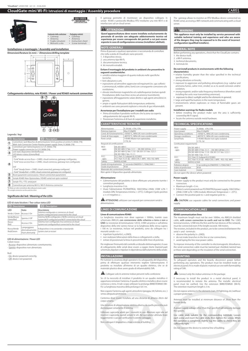
If necessary to install the product in a metal electrical panel, it is
recommended to remote the antenna.The metallic electrical panel must
be earthed. Use the extension BMBSTEWA00 (Wi-Fi) or BMBSTEGA00
(2/4G). The extention maximum length is 3 m, for Wi-Fi and 2G/4G.
Not exposure the antenna to the atmospheric agent (rain, UV lightning,
etc.) without a proper protection.
Anyway antennas must be installed at minimum distance of 20cm from
the human body.
A power supply voltage other than that specied will seriously damage
the system;
Use cable ends suitable for the corresponding terminals. Loosen
each screw and insert the cable ends, then tighten the screws. When
the operation is completed, slightly tug the cables to check they are
suciently tight.
Do not connect the device to external line of building.
FIRST COMMISSIONING PROCEDURE
Connect to the tERA platform via PC or tablet, access the“Conguration”
menu and follow the procedure.
If required by procedure, insert the Serial Number
and Security Code indicated on the product label,
placed under the front cover.
ATTENTION: only when all line controllers have been correctly
detected can installation be concluded and the plant be abandoned.
TEMPORARY IP ASSIGNMENT
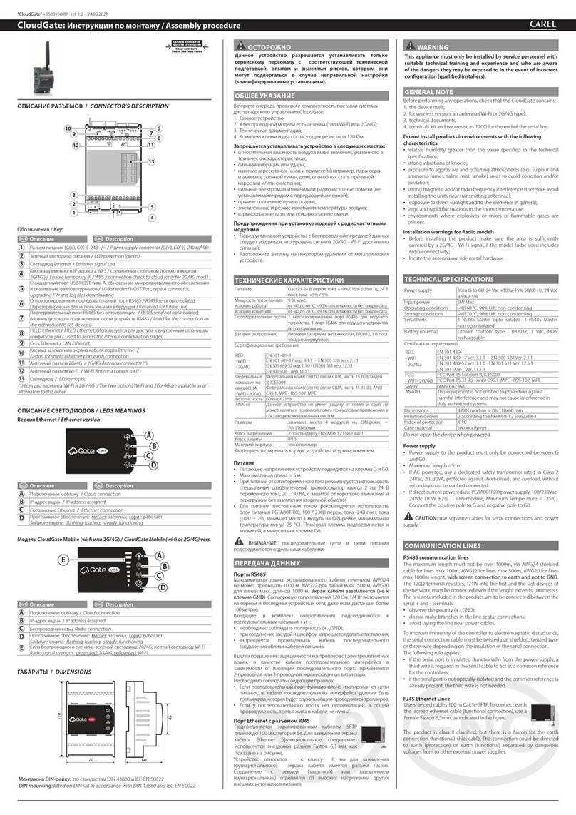
To assign a temporary IP address to the Cloudgate LAN port for access
when the actual IP is not known, proceed as follows:
• press and hold the “Enable temporary IP button”(4) for 2 seconds
• the a "obtaining IP address" (B) alarm LED - will start ashing green
• CloudGate can now be accessed at IP address 172.16.0.33/16 for
around one hour, after which the temporary IP will be automatically
disabled.
WPS FUNCTION FORWIFI MODELS
To pair the Cloudgate to router Wi-Fi, using the WPS function, to have an
internet access, proceed as follows:
• press and hold the “Enable temporary IP button”(4) for 10 seconds;
• the "minimum radio signal power" (E) LED will start ashing green;
• now start WPS functionality in the router;
• as soon as CloudGate has been paired to the router, the "obtain IP
address" (B) LED will light up together with the radio signal intensity
LED (E).
Note: the WPS functionality will be active (pending pairing) for about
2 minutes
CONNECTION CHECK TO CLOUD ONLY MOD.
2G/4G:
To verify the correct connection of the device to the cloud, proceed as
follows:
• press and hold the “Enable temporary IP button”(4) for 10 seconds;
• the "minimum radio signal power" (E) LED will start ashing green;
• as soon as CloudGate has been paired to the router, the "obtain IP
address" (B) LED will light up;
• wait about 1 minute for "cloud connection" (A) lights up to obtain
conrmation of the correct connection to the cloud.
FACTORY RESET FACTORY DATA RESET
If it is necessary to reset the CloudGate to the default settings (initial
start-up, deleting the conguration, historical data and any updates
installed), proceed as follows:
• disconnect power from the Cloudgate;
• power on pressIng and holding the “Enable temporary IP button” (5)
for about 5s;
• "SW motor" LED (D) will start ashing slowly;
• when it starts ashing quickly, release the button;
• the "SW motor" LED (D) will start to ash slowly for about 5s;
• when the "SW motor" LED starts ashing quickly, press the button
again and keep it pressed until the LED stops ashing;
• the "factory reset" procedure is in progress and the key can be
released and CloudGate restarted.
Note: the technical leaet is available in other languages and can
be downloaded from the website www.carel.com (in the section
"Cloudgate/Technical Lefalet: https://www.carel.com/product/
cloudgate).
CAUTION
This equipment has been tested and found to comply with the limits for a Class B digital device, pursuant
to Part 15 of the FCC Rules. These limits are designed to provide reasonable protection against harmful
interference in a residential installation. This equipment generates, uses and can radiate radio frequency
energy and, if not installed and used in accordance with the instructions, may cause harmful interference
to radio communications. However, there is no guarantee that interference will not occur in a particular
installation. If this equipment does cause harmful interference to radio or television reception, which
can be determined by turning the equipment o and on, the user is encouraged to try to correct the
interference by one of the following measures:
• Reorient or relocate the receiving antenna.
• Increase the separation between the equipment and receiver.
䄜⟄㈐ /
MAIN WARNINGS
⪇䐤䐙㚰/ GUIDELINES FOR DISPOSAL
ⷚ㈾⭒⭹㻷㾱⳰㹐⪇㏎ⳉ⺇⡹㿌⭆Ⱑ⪇䐤ⶤ㪉⡙〓⥛㠘᱄
㤌㹑ㅌⶤ⥛㠘䔘㸋⧨㬱㎍〙⪇㏎⡹㿌㵉⺞䓉䄖⳰㹐⪇㏎䐱㾥㆙㾱⪇䐤᱄
⡟⥛㠘⟝⼍䄜ㅻ⮈⧹䊻⪇䐤⡟⥛㠘䐏㣑⡹㿌ⷚ㈾㳂⹊⭥㯖㘘ㅌ⮈⧹㦂
⨗⤃䈌㡅㰝⥛㠘⤠ミ㋋᱄
⡟⥛㠘㬚䇤⤜⭒〓⪇䐤⤜⭒。ⰵ㦬㳆ㅂ㋖⼮㈔䋍⧪⤜㑝䇑㼍᱄
䄜⭊⳨ⳉ⪇䐤⮈㡙⼮⮈䓴⳰㠘ⷚ㈾⭒⭹⳰㹐⪇䐤ⳉ⺇ㅌ㬽⭞㼁䇇⪇Ⳅ᱄
•
The appliance (or the product) must be disposed of separately in accordance with the
local waste disposal legislation in force.
•
Do not dispose of the product as municipal waste; it must be disposed of through
specialist waste disposal centres.
•
The product contains a battery that must be removed and separated from the rest of
the product according to the instructions provided, before disposing of the product.
•
Improper use or incorrect disposal of the product may negative eects on human
health and on the environment.
•
In the event of illegal disposal of electrical and electronic waste, the penalties are
specied by local waste disposal legislation.
䐹䄋㈐ /
IMPORTANT WARNINGS
CAREL⭥⥛㠘㬨䔏㻩㆙⥛㠘⭥⫛⢎䐏䄜㰇⥛㠘㳂⹊⭥ゝ㭖㸥ミ䐱⺇Ⰹ㑬⤺䔘㯖
㘘䄓㋪䊻⹛㕓㣑⪴㶙䍟www.carel.com㩰㻣䊹ⶤ⤺䔘㯖㘘᱄㋮⿈䔏䐶㪉⡙䐧䋍㩭᱃
㋋ⳃ㩭〓➓䓑㩭⧱⭄䈌⥛㠘㞅䐤ㅸⰯ䇱⭥㰚䇱䋑㦯⼮ⴈ㻶⪬㈺䐝䊻⪺㬚㬖㻷䈌
㲹Ⰹ䔏䐶➓䓑⼮〓㪉⡙䇱⭥䊅㠻ㆂ⺜᱄㧈⺜䇤⿈㬷⥂䐱䄋㤔⺇Ⰹ⭥䁈㻑ㅸⰯ㸕䈉
㕛䔄ㅌ。⭝䐣䔏䐶⥛㠘⨗㻷䍰CARELⰵ⪬ⶦ⤜⧱⭄㦯⼯䋑㦯᱄䔏䐶㋮⿈⡹㿌➕䍶
䈌⥛㠘⡟㪎㼁⭥㸥ミ䓫㑰䐱⺇Ⰹ⭥Ⳟ㬞㬚䇤⡟⥛㠘᱄CARELⰵ䓵゛⥛㠘⭥䋑㦯䇇㬽㶙
䍟www.carel.com㩰㑱㬟⭥CAREL䄜⟄⼰㵍㳖ミ⼮〓䈌㋮⿈Ⰺ㑃⭥㲹Ⰹ㾎䅊⭥䊝㭙᱄
The CAREL product is a state-of-the-art product, whose operation is specied in the technical
documentation supplied with the product or can be downloaded, even prior to purchase, from
the website www.carel.com. - The client (builder, developer or installer of the nal equipment)
assumes every responsibility and risk relating to the phase of conguration the product in order to
reach the expected results in relation to the specic nal installation and/or equipment. The lack of
such phase of study, which is requested/indicated in the user manual, can cause the nal product
to malfunction of which CAREL can not be held responsible. The nal client must use the product
only in the manner described in the documentation related to the product itself. The liability of
CAREL in relation to its own product is regulated by CAREL’s general contract conditions edited on
the website www.carel.com and/or by specic agreements with clients.
接线图 /
CONNECTIONS DRAWING
RC 䐈⧷
SUPPORT
㧈⺜㪉⡙ⳃ㪛䍰㤌䈌㛛⭥CARELゝ㭖
䐈⧷㦬䊒㑋㻖᱄㧈䇱㦯⼯䄪㸫〓䄪㔨
In case of device malfunctions contact
CAREL support personnel. For any
questions or concerns, please contact
"CloudGate" +0500150EZ - rel. 1.2 - 24.09.2021
• Connect the equipment into an outlet on a circuit dierent from that to which the receiver is
connected.
• Consult the dealer or an experienced radio/TV technician for help.
FCC Caution: Any changes or modications not expressly approved by the party responsible for
compliance could void the user's authority to operate this equipment.
This device complies with Part 15 of the FCC Rules. Operation is subject to the following two conditions:
(1) this device may not cause harmful interference, and
(2) this device must accept any interference received, including interference that may cause undesired
operation.
FCC RF Radiation Exposure Statement:
1. This Transmitter must not be co-located or operating in conjunction with any other antenna or
transmitter.
2. This equipment complies with FCC RF radiation exposure limits set forth for an uncontrolled
environment. This equipment should be installed and operated with a minimum distance of 20
centimeters between the radiator and your body.
CAUTION
1. “CAUTION” Risk of explosion if the battery is replaced by an incorrect type or short circuit;
2. Never open the equipment. For safety reasons, the equipment should be opened only by qualied
skilled person;
3. can only be safely used lower than 2000 meters altitude
小心
⡟㪉⡙䄲㈎⺞⥃㬵䐅㘘㡅ⴜ⼰FCC⺇䋓⭻15⤠䐱䇻B㏁㭞䓷㪉⡙⭥㻿䐧⺇Ⰹ᱄䎃㾊㻿䐧⺇
Ⰹ䐝䊻㸋䓂䍍➓䓑㈔䐱⭥䇱⼇ⶪ㦦㳂⹊⼰㏎⡄⿅᱄⡟㪉⡙。⥛㪛᱃㬚䇤⼮ⴙ㪅㪅㠖㚽㑠
㧈⺜㸕➕㯖㘘㭊㆙㾱➓䓑⼮㬚䇤㚨㗕。ⰵ㸿㼀⮈㵉㾦䋍⧪䇱⼇ⶪ㦦᱄⪬㶃㲹Ⰹ➓䓑䐱㬨
ⴒⳃ㪛ⶪ㦦䅁㸿ⳉ⡄䐅᱄㧈⺜ⶤ㪉⡙㦘㬖ⰵ㸿㼀⮈〓⮈㬴ㅴ㬶䋍⧪㑬䇱⼇ⶪ㦦㋪䄵㵉⺞⫓
㋋⼮⡶㪉⡙㎕㦘Ⰹ䊻⪬ㅉ䅊䇤⿈⧃㬵㵉⺞䄵㻣⫌㬊䐏䄜䇇ⰵⶤⶪ㦦
䐹㾣⮘䎜〓Ⰹ㸜ㅴ㬶㳍㼀
䋗ゴⶤ㪉⡙䈌ㅴ㬶㡘䐏ヅ⭥㉁㏌
ㅌⶤ㪉⡙㑍ㅴ⭞ㅴ㬶㡘㑍ㅴ⮈㔘䄵㶃⭥㡅㰝⮈㔘⥆䔚㩰
䓪䁐㈎㼛㩭〓䇱㈎䂊⭥㸿㼀⮈⮈㬴ゝ㭖㦬䊒䄵䁑㤔䓉䄖⟐䑛᱄
FCC㈐㸕㈎⼰⺇䋑㦯Ⳟ㘘㦘㞛䓝⭥㦯⼯⢅Ⱀ〓㾿ⶥ㋪㚽。㬚䇤⿈㩆㬈⤺䔘ⶤ㪉⡙⭥㦉
㻿᱄
ⶤ㪉⡙ⴜ⼰FCC⺇䋓⭥⭻15⤠᱄㪉⡙ⴜ⼰䄵㻣㑞⫔㳖ミ
(1) ⶤ㪉⡙⤜。䋍⧪䇱⼇ⶪ㦦⤃㣳
(2)ⶤ㪉⡙⡹㿌ㅴ㬽㰚㬶⭞⭥㦯⼯ⶪ㦦⟝㎉㋪㚽⭝䐣䅃㶃⤺䔘⭥ⶪ㦦᱄
FCC RFⴙ㪅⡊㔗㪚㘘
ⶤⳃ㪅㡘⤜⭤䈌㡅㰝㦯⼯㳍㼀〓ⳃ㪅㡘⳦䊻䄜㡑〓㵍㬒㬚䇤᱄
ⶤ㪉⡙ⴜ⼰䇱⳨㬽㋹㈔⭥FCC RFⴙ㪅⡊㔗㻿䐧䄋㤔᱄ⶤ㪉⡙⭥➓䓑⼮
䊬㾱䇇㦘⡄㩃㦩㡘䈌㦬㳆䐏ヅ⭥䔏㾂㉁㏌㸋20㏆㗸᱄
小心
᱑㾂㾥᱒㧈⺜ⷝ㑬⫎㹔㏁㾮⭥⮈⧹〓䎀⮈⧹Ⱝ㔘。⫇䊻⡍䍉⭥ⴈ
㻶
㣱㹑⫓㋋㪉⡙᱄⨗䇻➓㦌䊎䅓䐜㚽䇪⼰ⷒゝ㭖㦬䊒⫓㋋ⶤ㪉⡙
3. 䐜䇱䊻2000㗸䄵㻣⭥⼄➯ⷀⰩ㈔䐱⤦㚽➓㦌㬚䇤ⶤ㪉⡙᱄
