manuals.online logo
Brands
  1. Home
  2. •
  3. Brands
  4. •
  5. Carel
  6. •
  7. Gateway
  8. •
  9. Carel GTW 0BT0 Series User manual

Carel GTW 0BT0 Series User manual

+050002725 - rel. 1.3 - 30.07.2019
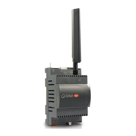
Wireless Gateway: GTW**0BT0: Gateway Serial RS485/TTL to Bluetooth / GTW**0WT0: Gateway Serial RS485/TTL to WiFi
Installazione e montaggio /
Assembly and installation
Dimensioni/forature (in mm) /
Dimensions/drilling template
25
41
48
60
70
Ø 4
25
63.5
Collegamento elettrico, rete RS485 /
Power and RS485 network connection
1
2
3
45
6
7
POWER
LINK
DC:5~36V DC:5~36V
Reset
Serial
TTL
RS485
Gateway
Serial to Bluetooth
1
2
3
4
567
POWER
LINK
DC:5~36V DC:5~36V
Reset
Serial
TTL
RS485
Gateway
Serial to WiFi
Legenda /
Legende:
1Porta seriale RS485
RS485 Serial Port
2Porta serialeTTL (per connettersi ai controlli parametrici come IR33
modbus - senza l’uso di IROPZ485xx)
TTL Serial Port (to connect to parametric controller as IR33 modbus -
without use of IROPZ485xx)
3Antenna Antenna
4Alimentazione Jack-Maschio Male-Jack Power supply
5Alimentazione morsetti a vite Screw power supply
6Led di stato:Verde = Link; Rosso = Power
Status leds:
Green = Link; Red = Power
7Tasto di reset Reset button
NOTE COLLEGAMENTI ELETTRICI:
• Utilizzare cavo schermato per realizzazione del cablaggio rete RS485.
• Collegare la resistenza di terminazione da 120Ω sull’ultimo
dispositivo della rete RS485; numero massimo di dispositivi
Modbus collegabili alla porta RS485 è pari 10 e la lunghezza
massima della rete è 100m.
• L’utilizzo della porta TTL è alternativa alla porta RS485, per
orire la connessione diretta del dispositivo Modbus senza
l’ausilio dell’opzione seriale IROPZ*. In questo caso il numero
max di dispositivi Modbus collegabili al gateway è pari a 1.
NOTES ON ELECTRICAL CONNECTIONS:
•
Use shielded cables for wiring the RS485 network.
•
Connect a 120 Ω terminating resistor on the last device in
the RS485 network; a maximum of 10 Modbus devices can
be connected to the RS485 port, and the maximum network
length is 100 m.
•
The TTL port can be used as an alternative to the RS485 port,
porviding a direct connection of the Modbus device without
requiring the IROPZ* serial option. In this case, only 1 Modbus
device can be connected to the gateway.
Bluetooth version Wi- version
Disposal of the product: The appliance (or the product) must be disposed of separately in compliance with the local standards in
force on waste disposal.
Contenuto della confezione
Packaging contents
• Gateway •
Gateway
• Antenna •
Antenna
• Foglio istruzioni •
Instruction sheet
• Morsetti a vite •
Screw terminals
Igatewaywirelesssono convertitoridareteseriale ModbusRTUaWi-Fio Bluetooth,concomunicazione bi-direzionale. The wireless gateways are converters from a Modbus RTU serial network toWi-Fi or Bluetooth, with two-way communication.
Avvertenze d’installazione: per un montaggio corretto contattare un montatore qualicato. Non installare prodotti
in ambienti aventi le seguenti caratteristiche:
• umidità relativa superiore al valore specicato nelle caratteristiche tecniche;
• forti vibrazioni o urti;
• esposizione ad atmosfere aggressive e inquinanti (ad es.: fumi di zolfo e ammoniaca, nebbia salina, fumo) per
evitare corrosione e/o ossidazione;
• forti interferenze magnetiche e/o di radiofrequenze (pertanto si sconsiglia di montare le unità vicino alle antenne
di trasmissione);
• esposizione a luce solare diretta o elementi atmosferici in genere;
• importanti e rapidi uttuazioni della temperatura ambiente;
• ambienti nei quali sono presenti esplosivi o miscele di gas inammabili.
È necessario rispettare i seguenti avvertimenti:
• AVVERTENZA: per i collegamenti elettrici, rispettare la polarità indicata sul connettore all’interno della scatola;
• utilizzare unicamente cavi schermati per la rete di comunicazione RS485;
• tensioni di alimentazione diverse da quelle specicate possono gravemente danneggiare il sistema;
• usare dei capicorda appropriati per i relativi morsetti. Allentare le singole viti e inserire i capicorda, quindi serrare le
viti. Al termine, tirare leggermente i cavi per accertarsi che siano tesi a sucienza;
• non aprire il prodotto quando è alimentato
Installation warnings: for correct installation contact a qualied installer. Do not install products in environments
with the following characteristics:
• relative humidity greater than the value specied in the technical specications;
• strong vibrations or knocks;
• exposure to aggressive and polluting atmospheres (e.g.: sulphur and ammonia fumes, saline mist, smoke) so as to
avoid corrosion and/or oxidation;
• strong magnetic and/or radio frequency interference (therefore avoid installing the units near transmitting
antennae);
• exposure to direct sunlight or the elements in general;
• large and rapid uctuations in the room temperature;
• environments where explosives or mixes of ammable gases are present.
The following warnings must be observed:
• IMPORTANT: For the electrical connection, maintain the polarity indicated on the connector included in the box;
• only use shielded cables for the RS485 communication network;
• power supply voltages other than those specied may seriously damage the system;
• use cable ends suitable for the corresponding terminals. Loosen each screw and insert the cable ends, then tighten
the screws.When nished, slightly tug the cables to check they are suciently tight;
• do not open the product when powered.
Led di Stato e tasto Reset:
Led di alimentazione, colore rosso: Acceso: dispositivo alimentato correttamente; Spento: dispositivo non alimentato
Led di connessione, colore verde: Acceso: dispositivo connesso ad una rete Wi-Fi o un dispositivo Bluetooth (in funzione
del modello); Spento: dispositivo non connesso a reteWi-Fi o Bluetooth; Lampeggiante: in fase di reset (dopo pressione tasto)
Tasto reset: se premuto per un tempo maggiore di 5 secondi al rilascio comporta il reset del gateway alle impostazioni di
fabbrica (confermato dal lampeggio del led verde).
Status LED and Reset button:
Red power LED: On: device powered correctly; O: device not powered
Green connection LED: On: device connected to aWi-Fi network or a Bluetooth device (depending on the model);
O: device not connected toWi-Fi or Bluetooth; Flashing: reset in progress (after pressing the button)
Reset button: if pressed for more than 5 seconds, on releasing the gateway is reset to the factory settings (conrmed
by the green LED ashing).
Messa in servizo GATEWAYWI-FI con BOSS
Prima accensione al gatewayWi-Fi:
• Ricercare la reteWi-Fi creata dal gateway, il nome (SSID)
di default della rete creata dal gateway è
CAREL_GTW_
SERIAL2WIFI_XXXXXX
, dove XXXXXX corrisponde
agli ultimi byte dell’indirizzo MAC. Il MAC è riportato
nell’etichetta applicata al prodotto.
• Collegarsi a questa reteWi-Fi con un PC o altri dispositivi
(di default la rete non ha password).
• Aprire un browser (es. Chrome) e digitare l’indirizzo
http://10.10.100.254.
• Si aprirà una pagina login, immettendo credenziali user:
“admin”e la password:“admin”, si accede alla pagina di
congurazione.
• Entrare nella voce di menuWi-Fi setting, e congurarla
come da immagine (vedi gura 1)
Setting up WI-FI GATEWAY with BOSS
Switching on theWi-Fi gateway the rst time:
• Search for theWi-Fi network created by the gateway, the
default network name (SSID) created by the gateway is
CAREL_GTW_SERIAL2WIFI_XXXXXX
, where XXXXXX
are the nal bytes of the MAC address.The MAC address
is shown on the label axed to the product.
• Connect to thisWi-Fi network with a PC or other device
(by default the network has no password).
• Open a browser (e.g. Chrome) and type in the address
http://10.10.100.254.
• A login page will open for entering the user credentials:
“admin” and password: “admin” to access the
conguration page.
• Enter the Wi-Fi setting menu item and congure it as
shown in the image (see Figure 1) Figura 1 /
Figure
1
WiFi Work Mode: STA mode il gateway funzionerà in modalità“STATION”, quindi si andrà ad agganciare ad una
reteWi-Fi i cui parametri sono impostabili nei campi seguenti:
Router SSID: boss-xxxx nome della reteWi-Fi di boss alla quale il gateway si deve agganciare. Si possono anche
ricercare le reti disponibili attraverso la funzione“Search”
STA Password: ****** password della reteWi-Fi di boss a cui ci si deve connettere.
DHCP: disabled gli indirizzi IP dei gateway connessi a boss devo essere gestiti in modalità statica
IP Address: 192.168.42.xx gli indirizzi assegnabili al gateway all’interno della rete Wi-Fi di boss deve essere
all’interno dell’intevallo 192.168.42.2 - 192.168.42.49. Assegnare per ogni gateway da connettere a boss un IP
all’interno di questo range (ogni gateway deve avere un IP dierente)
Mask: 255.255.255.0; Gateway: 192.168.42.1 / DNS: 192.168.42.1
WiFi Work Mode: STA mode the gateway will work in“STATION”mode, and will connect to a Wi-Fi network
whose parameters can be set in the following elds:
Router SSID: boss-xxxx name of the bossWi-Fi network that the gateway will connect to. It is also possible to
search for the available networks using the“Search”function
STA Password: ****** password for the bossWi-Fi network being connected to.
DHCP: disabled the IP addresses of the gateways connected to boss are managed in static mode
IP Address: 192.168.42.xx the addresses that can be assigned to the gateways on the bossWi-Fi network must
be in the range 192.168.42.2 - 192.168.42.49. Assign an IP within this range to each gateway to be connected to boss
(each gateway must have a dierent IP)
Mask: 255.255.255.0; Gateway: 192.168.42.1 / DNS: 192.168.42.1
Cliccare su “SAVE” e accettare la richiesta di riavvio del
Gateway (vedi gura 2)
Click “SAVE” and accept the request to restart the Gateway
(see Figure 2)
Figura 2 /
Figure
2
Speciche tecniche /
Technical specications
Hardware
Alimentazione /
Power supply:
:5…36V cc
Corrente di esercizio(moduloWiFi interno) /
Operating Current (internalWiFi module):
Normal mode: AP average:
74 mA, peak 285 mA; STA average: 32mA, peak 196 mA; Sleep mode: 6,5 mA; Deep dormancy: 90 μA
Temper. di
esercizio /
Operating temperature:
-10…60°C
Umidità di esercizio /
Operating Humidity:
5…95% UR (non-cond)
Interfaccia comune /
Common Interface:
RS485, TTL
Wireless
Wireless Standard: 802.11 b/g/n
Trasmis. di potenza /
Transmit power:
:802.11b: +18 ±1 dBm (@ 11 Mbps CCK); 802.11g: +17 ±1 dBm (@ 54 Mbp
OFDM); 802.11n: +15 ±1 dBm (@ HT20, MCS7)
Sensibilità di ricezione /
eceiving sensitivity:
:802.11b: -85 dBm (@ 11 Mbps CCK); 802.11g: -70 dBm (@ 54 Mbps
OFDM); 802.11n: -68 dBm (@ HT20 MCS7)
Antenna: Antenna ad asta esterna con un connettore non standard /
Antenna: Antenna external rod antenna with a
non-standard connector
Software
Tipi di rete Wireless /
Wireless Network Types
:AP / STAZIONE
Sicurezza WiFi /
WiFi Security:
:WEP/WPA-PSK/WPA2-PSK
WiFi Encryption: TKIP, AES,TKIP/AES
Gamma di frequenza di esercizio /
Operating frequency range
Bluetooth: 2402-2480 MHz - ax. tune-up power with tolerance -3±1,0 dBm
WiFi: 2412-2462 MHz - Max. tune-up power with tolerance 11B:18±1 dBm - 11G:17±1 dBm, 11N:15±1 dBm
IMPORTANTWARNINGS FOR FCC RULES
This device complies with Part 15 of the FCC Rules. Operation is subject to the following two conditions:
1. this device may not cause harmful interference, and
2. this device must accept any interference received, including interference that may cause undesired operation.
Caution: Theuser iscautioned thatchanges or modicationsnot expresslyapproved bythe party responsibleforcompliance couldvoid
the user’s authority to operate the equipment.
Note: This equipment has been tested and found to comply with the limits for a Class B digital device, pursuant to part 15 of the
FCC Rules. These limits are designed to provide reasonable protection against harmful interference in a residential installation. This
equipment generates, uses and can radiate radio frequency energy and, if not installed and used in accordance with the instructions,
may cause harmful interference to radio communications. However, there is no guarantee that interference will not occur in a particular
installation. If this equipment does cause harmful interference to radio or television reception, which can be determined by turning the
equipment o and on, the user is encouraged to try to correct the interference by one or more of the following measures:
• Reorient or relocate the receiving antenna.
• Increase the separation between the equipment and receiver.
• Connect the equipment into an outlet on a circuit dierent from that to which the receiver is connected.
• Consult the dealer or an experienced radio/TV technician for help.
• This equipment complies with FCC radiation exposure limits set forth for an uncontrolled environment. This equipment should be
installed and operated with a minimum distance of 20cm between the radiator and any part of your body.
A questo punto si verrà sconnessi dalla rete Wi-Fi del gateway (
CAREL_
GTW_SERIAL2WIFI_XXXXXX
). Collegarsi ora, attraverso il proprio
dispositivo, alla rete Wi-Fi di boss (stessa selezionata nel gateway come
“
Router SSID: boss-xxxx
”), una volta connessi, nel browser digitare
l’indirizzo IP assegnato al gateway (http://192.168.42.x), si aprirà di
nuovo la pagina di login del webserver del gateway, quindi loggarsi (
usr:
admin/ psw: admin
) e:
- entrare nella voce di menu Trans Setting per congurarla come segue:
(vedi gura 3)
The device will then be disconnected from the gateway's Wi-Fi network
(
CAREL_GTW_SERIAL2WIFI_XXXXXX
). Now connect the device to the
boss Wi-Fi network (the same selected on the gateway as“
Router SSID:
boss-xxxx
”), and once connected, enter in the browser the IP address
assigned to the gateway (http://192.168.42.x); the gateway webserver
login page will open again, then log in (
usr: admin / psw: admin
) and:
- enter theTrans Setting menu item and congure it as follows:
(see Figure 3)
Figura 3 /
Figure
3
Dove va impostato: Serial Port Set: Baud Rate (1200-460800bps): la velocità di comunicazione Modbus RTU dei
dispositivi connessi alla porta RS 485 del gateway; Data Bit: data bit di comunicazione Modbus RTU dei dispositivi
connessi alla porta RS 485 del gateway; Check Bit: parità di comunicazione Modbus RTU dei dispositivi connessi alla
porta RS 485 del gateway. CTRTS/485: 485 - Network set: Mode:Trasparent
Socket A Connect Set: Protocol:TCP-Server; Port: 502; Server IP Address: non gestito, lasciare valori default
Socket B Connect Set: Protocol: non gestito, lasciare valori default; Port: non gestito, lasciare valori default;
Server IP Address: non gestito, lasciare valori default. Cliccare su“SAVE”e accettare la richiesta di riavvio del Gateway (gura2)
Set the following: Serial Port Set: Baud Rate (1200-460800bps): Modbus RTU communication speed for the devices
connected to the gateway’s RS485 port; Data Bit: Modbus RTU communication data bits for the devices connected to
the gateway’s RS485 port; Check Bit: Modbus RTU communication parity for the devices connected to the gateway’s
RS485 port. CTRTS/485: 485 - Network set: Mode:Transparent
Socket A Connect Set: Protocol:TCP-Server; Port: 502; Server IP Address: not managed, leave the default values
Socket B Connect Set: Protocol: not managed, leave the default values; Port: not managed, leave the default values;
ServerIPAddress:notmanaged,leavethedefault values.Click“SAVE”and accepttherequesttorestart theGateway(seeFigure2)
Connettersi ora alla pagina di congurazione linea
di boss e settare una nuova linea per ogni gateway
congurato con la seguente logica: (vedi gura 4)
Connection: Protocol: Modbus –TCP;
IP address: 192.168.42.x (lo stesso assegnato al
gatewayWi-Fi); ReceiveTimeout: 5000ms
Devices: Impostare quindi i dispositivi connessi alla
porta RS485 del Gateway come fossero connessi a
una porta RS485 di boss (vedi gura 5).
Now connect to the boss line conguration page and set a new line
for each gateway congured, with the following logic: (see Figure 4)
Connection: Protocol: Modbus –TCP;
IP address: 192.168.42.x (the same assigned to theWi-Fi
gateway); ReceiveTimeout: 5000ms
Devices:Then set the devices connected to the gateway’s RS485
port as if they were connected to a boss RS485 port (see Figure 5).
Figura 4 /
Figure
4
Il gateway Wi-Fi è compatibile solo con boss e boss-mini con a
bordo la versione SW 1.4.0 o successive.
Note agguntive per la fase installazione: per vericare il livello del segnale
radio della rete Wi-Fi di boss in prossimità del punto di installazione del
Gateway, è suciente utilizzare una delle APP-free scaricabili da PlayStore/
AppStore, che ne misurano l’intensità e la distanza“calcolata”dall’access-point
(boss). Nel caso il segnale risulti debole per elevata distanza, o la distanza
calcolata dall’APP è molto maggiore di quella reale, causa ostacoli presenti
in ambiente che attenuano il segnale radio di boss, è necessario utilizzare dei
ripetitoristandardsegnaleWi-Fi,perestendere/potenziarelareteWi-Fidiboss.
The Wi-Fi gateway is only compatible with boss and boss-mini
devices with SW 1.4.0 or higher (see Figure 5)
Additional notes for installation: to verify the wireless signal level of
the bossWi-Fi network in the place where the gateway will be installed,
simply use one of the free apps downloadable from PlayStore/AppStore to
measure the signal strength and the“calculated”distance from the access-
point (boss). If the boss wireless signal is weak due to large distance, or
the calculated distance by the APP is much greater than the real one, due
to obstacles in the room that attenuate the signal, a standardWi-Fi signal
repeater has to be used to extend/boost the bossWi-Fi network.
Figura 5 /
Figure
5
Modbus®
Modbus®
GTW0000WT0
c.pCo
ir33
GTW0000WT0
c.pCo
ir33
Modbus®
Modbus®
Messa in servizio Gateway con APP-Carel:
VERSIONE WI-FI: - Attraverso la APP CAREL ricercare il dispositivoWi-Fi
“CAREL_GTW_SERIAL2WT_xxxxxx”
(dove xxxxxx sono i 3 byte nali dell’indirizzo MAC riportati in etichetta prodotto)
- Collegarsi a quest’ultimo e seguire le indicazioni fornite dalla APP stessa.
Nota:
Il Gateway per questo utilizzo funziona in modalità
“AP”
, se è necessario cambiare nome della rete SSID connettersi attraverso un dispositivoWi-Fi al webserver
del Gateway e impostarlo nella sezione“AP mode”. Per modicare i parametri della comunicazione seriale agire nella sezione“Trans setting”.
VERSIONE BLUETOOTH: - Attraverso la APP CAREL ricercare il dispositivo Bluetooth “CAREL_GTW_SERIAL2BT_xxxxxx”(dove xxxxxx sono i 3 byte nali dell’indirizzo MAC riportati in etichetta prodotto). - Collegarsi a quest’ultimo e seguire le
indicazioni fornite dalla APP.
Nota:
Il Gateway in versione BT è impostato di default per funzionare con i seguenti settaggi nella porta seriale:
baudrate: 19200 / data bit: 8 / stop bit: 1 / parity: none.
Se necessario cambiare questi parametri (o
il nome del dispositivo BT): connettersi attraverso un PC alla porta seriale RS485 e utilizzando i comandi AT che seguono modicarli: Nome: Lettura: AT+NAME?<CR>; Scrittura: AT+NAME=<Name><CR>
Parametri porta seriale: Lettura: AT+UART?<CR> - Scrittura: AT+UART=<Baudrate>,<Data bits>,<Parity>,<Stop bits><CR> Dove: <Baudrate> range 2400-115200; <Data bits> range 5,6,7,8; <Parity> range 0:No parity
1:Odd parity 2:Even parity; <Stop bits> range 0:1 stop bit 1:1.5 stop bits 2:2 stop bits. I nuovi parametri sono validi dopo un riavvio del gateway (togliere/dare tensione di alimentazione)
Setting up the Gateway with the Carel APP:
WI-FI VERSION: - Using the CAREL APP, search for theWi-Fi device
“CAREL_GTW_SERIAL2WT_xxxxxx”
(where xxxxxx are the nal 3 bytes of the MAC address shown on the product label)
- Connect to the device and follow the instructions provided in the APP.
Note
: In this case the gateway use works in
“AP”
mode; if needing to change the name of the SSID network, use aWi-Fi device to connect to the Gateway webserver and
set it in the“AP mode”section.To modify the serial communication parameters, go to the“Trans setting”section.
BLUETOOTH VERSION: - Using the CAREL APP, search for the Bluetooth device“CAREL_GTW_SERIAL2BT_xxxxxx”(where xxxxxx are the nal 3 bytes of the MAC address shown on the product label). - Connect to the device and follow the
instructions provided in the APP.
Note:
In the BT version, the gateway is set by default to work with the following serial port settings:
baudrate: 19200 / data bits: 8 / stop bits: 1 / parity: none.
If needing to change these parameters (or the
name of the BT device): connect a PC to the RS485 serial port and use the following AT commands to modify the settings: Name: Read: AT+NAME?<CR>; Write: AT+NAME=<Name><CR>
Serial port parameters: Read: AT+UART?<CR> - Write: AT+UART=<Baudrate>,<Data bits>,<Parity>,<Stop bits><CR> Where: <Baudrate> range 2400-115200; <Data bits> range 5,6,7,8; <Parity> range 0:No parity 1:Odd
parity 2:Even parity; <Stop bits> range 0:1 stop bit 1:1.5 stop bits 2:2 stop bits. The new parameters will be eective after restarting the gateway (power o/on).
Funzionalità generali del GATEWAY:
Modalità AP (Access Point): oltre alla modalità
STATION
(STA)
utilizzata per la connessione a Boss, il GatewayWi-Fi può
funzionare anche in modalità Access Point (AP), creare quindi
una propria rete. I parametri impostabili di questa rete Wi-Fi
sono i seguenti: (vedi gura 1)
• Network Name (SSID): default
CAREL_GTW_SERIAL2WIFI_
XXXXXX.XXXXXX
corrisponde agli ultimi byte dell’indirizzo MAC
• Password: nessuna password di default, visualizzazione“NONE”
• Indirizzo IP: default 10.10.100.254
• Mask: 255.255.255.0
General features of the GATEWAY:
AP (Access Point) mode: in addition to
STATION (STA) mode
used for the connection to boss, the Wi-Fi Gateway can also
work in Access Point (AP) mode, thus creating its own network.
The parameters that can be set for this Wi-Fi network are as
follows: (see Figure 1)
• Network Name (SSID): default
CAREL_GTW_SERIAL2WIFI_
XXXXXX.XXXXXX
corresponding to the nal bytes of MAC address
• Password: no password by default, display“NONE”
• IP address: default 10.10.100.254
• Mask: 255.255.255.0
CAREL INDUSTRIES HQs
Via dell’Industria, 11 – 35020 Brugine – Padova (Italy) - Tel. (+39) 049 9716611 – Fax (+39) 049 9716600 - e-mail: [email protected] – www.carel.com +050002725 - rel. 1.3 - 30.07.2019

This manual suits for next models

1

Other Carel Gateway manuals

Carel CloudGate-mini Wi-Fi Manual

Carel

Carel CloudGate-mini Wi-Fi Manual

Carel CloudGate Manual

Carel

Carel CloudGate Manual

Carel WEB-GATE WEBG0000B0 User manual

Carel

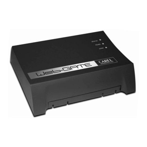
Carel WEB-GATE WEBG0000B0 User manual

Carel CloudGate User manual

Carel

Carel CloudGate User manual

Carel CloudGate Manual

Carel

Carel CloudGate Manual

Carel CloudGate-mini Wi-Fi Manual

Carel

Carel CloudGate-mini Wi-Fi Manual

Carel CloudGate Manual

Carel

Carel CloudGate Manual

Carel CloudGate Manual

Carel

Carel CloudGate Manual

Carel CloudGate Manual

Carel

Carel CloudGate Manual

Carel GATEWAYBN0 User manual

Carel

Carel GATEWAYBN0 User manual

Carel CloudGate Manual

Carel

Carel CloudGate Manual

Carel CloudGate Manual

Carel

Carel CloudGate Manual

Carel CloudGate User manual

Carel

Carel CloudGate User manual

Popular Gateway manuals by other brands

Sigfox SMK Access Station Mini installation manual

Sigfox

Sigfox SMK Access Station Mini installation manual

MatchX Box US MX1702 user guide

MatchX

MatchX Box US MX1702 user guide

Toshiba XLTR-200 instruction manual

Toshiba

Toshiba XLTR-200 instruction manual

DEUTSCHMANN AUTOMATION UNIGATE SC232/485 instruction manual

DEUTSCHMANN AUTOMATION

DEUTSCHMANN AUTOMATION UNIGATE SC232/485 instruction manual

Pepperl+Fuchs VBG-EN-K20-D manual

Pepperl+Fuchs

Pepperl+Fuchs VBG-EN-K20-D manual

Milesight SG50 user guide

Milesight

Milesight SG50 user guide

Grandstream Networks GXW-410x user manual

Grandstream Networks

Grandstream Networks GXW-410x user manual

WELLTECH FXSO GATEWAY H.323 3701A - VERSION 2.1A manual

WELLTECH

WELLTECH FXSO GATEWAY H.323 3701A - VERSION 2.1A manual

Dinstar MTG200 user manual

Dinstar

Dinstar MTG200 user manual

Comtrol DeviceMaster EIP Series Hardware installation and configuration guide

Comtrol

Comtrol DeviceMaster EIP Series Hardware installation and configuration guide

Frontier FiOS-G1100 user guide

Frontier

Frontier FiOS-G1100 user guide

Teltonika TRB141 Recovery guide

Teltonika

Teltonika TRB141 Recovery guide

ERT VIPER user manual

ERT

ERT VIPER user manual

RTA 460BCA-NNA4 Product user guide

RTA

RTA 460BCA-NNA4 Product user guide

NetComm NL1901ACV Backup and Restore Configuration Guide

NetComm

NetComm NL1901ACV Backup and Restore Configuration Guide

purexx PX-iP operating manual

purexx

purexx PX-iP operating manual

RTA 460MSTCP-NNA4 Product user guide

RTA

RTA 460MSTCP-NNA4 Product user guide

Technicolor TG650S Setup and user guide

Technicolor

Technicolor TG650S Setup and user guide

manuals.online logo
manuals.online logoBrands
  • About & Mission
  • Contact us
  • Privacy Policy
  • Terms and Conditions

Copyright 2025 Manuals.Online. All Rights Reserved.