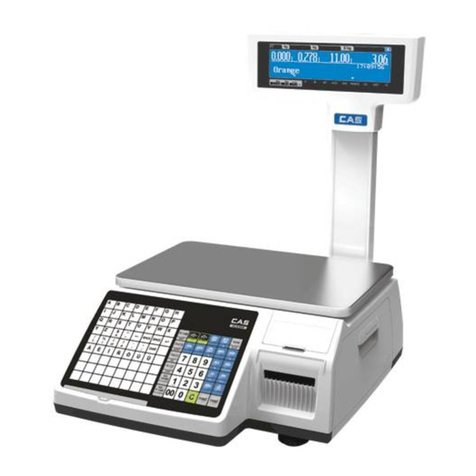
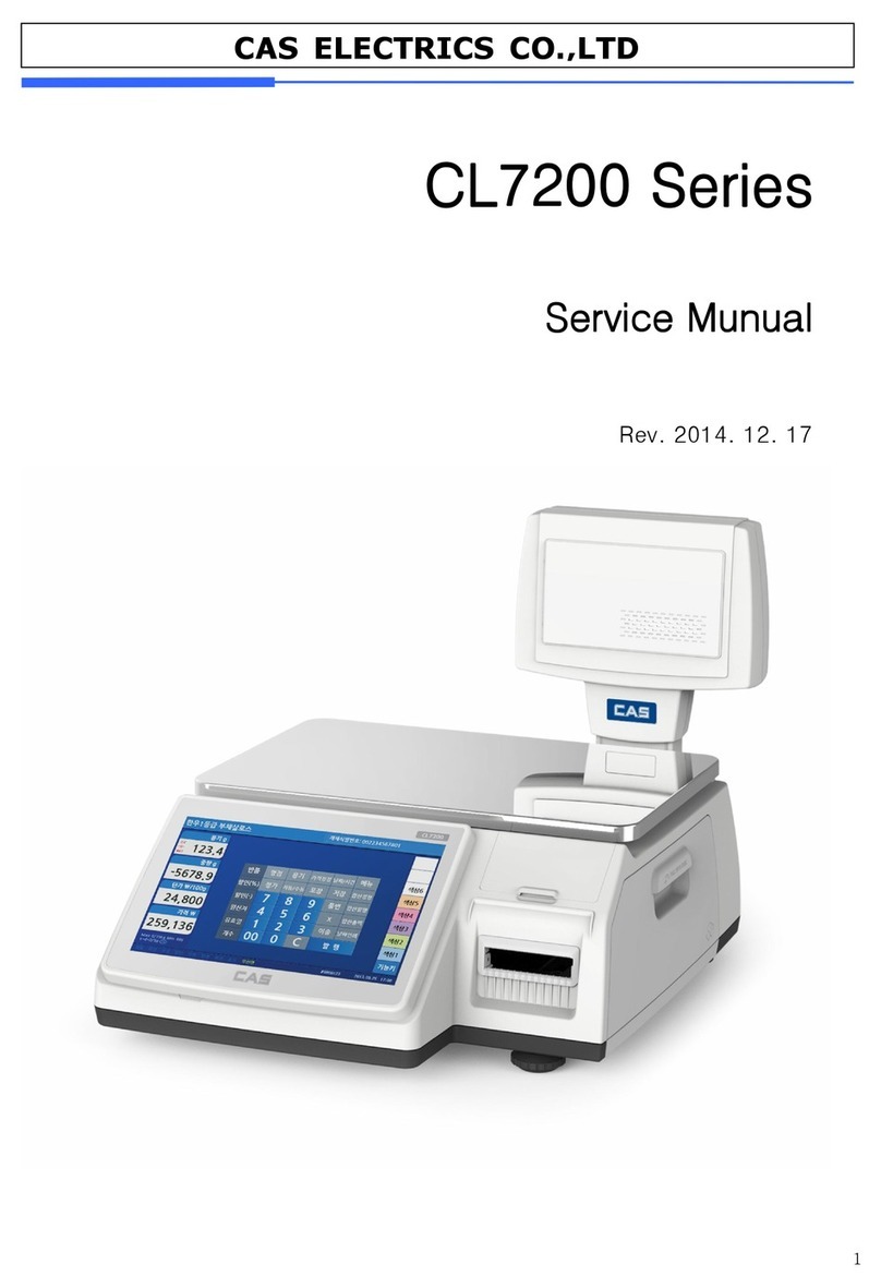
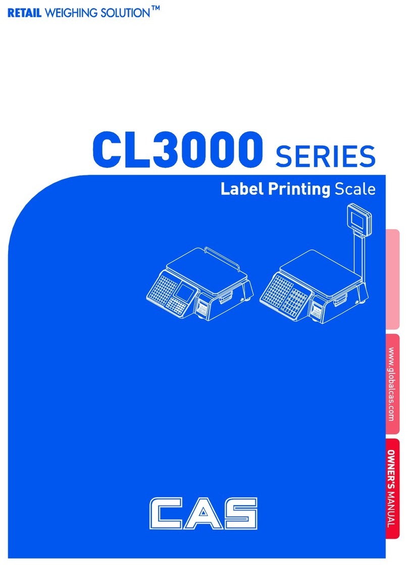
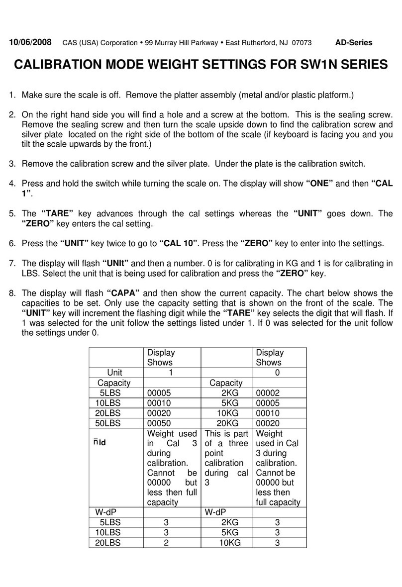
CAS CL3500 Series User manual

1
CAS ELECTRICS CO.,LTD
CL3500 Series
Service Manual
(English)
Rev. 2012. 05. 29

2
CAS ELECTRICS CO.,LTD
Table of Contents
1. Proper Operation ................................................................................................................................................5
1.1 Introduction..............................................................................................................................................5
1.2
Model and Specificationl ..................................................................................................................6
1.3 Environmental Conditions & Safet .......................................................................................................7
1.4 Leveling and Footer Location .................................................................................................................8
1.5
Power Outlet and Requirements ................................................................................................... 10
2. Classification .................................................................................................................................................... 11
2.1 Scale Overview ..................................................................................................................................... 11
2.2 Displa and Indicators .......................................................................................................................... 12
2.3 Printer ................................................................................................................................................... 14
2.4 Commuication ....................................................................................................................................... 15
2.5 Ke Pad ................................................................................................................................................. 16
3. Getting Started .............................................................................................................................................. 17
3.1 Sealing Method ..................................................................................................................................... 17
3.2 Installation o f th e L a b e l Roll ................................................................................................................ 18
3.3 Turning Power On/Off ............................................................................................................................ 20
3.4 Program Menu and Tree ...................................................................................................................... 21
3.4. 1 H o w to access PROGRAM MODE .............................................................................................. 21
3.4. 2 Program Menu Tree ..................................................................................................................... 22
3.4. 3 C alib r a tion Menu Tree ............................................................................................................... 24
4. Calibration Mode ........................................................................................................................................... 25
4.1 Calibration............................................................................................................................................. 25
4.1. 1 S p a n Calibration (Menu C o d e 8110) ............................................................................................ 26
4.1.2 Span/Zero Fine Adjust (Menu Code 8120) ............................................................................... 28
4.1. 3 C ap a c it & Units (Menu Code 81 30) ........................................................................................ 30
4.1. 4 G ra vit Constant (Menu Code 8140) ......................................................................................... 31
4.1. 5 Pe r c ent Calibra tion (Men u C o d e 8150) ..................................................................................... 32
4.1. 6 Lin e arit Adjust (Menu Code 8160) .......................................................................................... 33
4.1. 7 Ze r o & Tare Setting (Menu Code 8170) ................................................................................... 34
4.2 F a c to r Setting (Menu Code 8180) ..................................................................................................... 35
4.2. 3 A /D In itialize (Menu Code 8183) ............................................................................................... 3 5
4.2.4 Linearit Fine Adjust (Menu Code 8184) .................................................................................. 36
4.2.5
Hysteresys Calibration
(Menu Code 8185) ................................................................................. 37
4.3 Memor Clea r ....................................................................................................................................... 39
4.3. 1 C le ar R e p ort (Menu Code 8211) ............................................................................................... 39
4.3. 2 C le ar All PLU (Menu C o d e 8212) .............................................................................................. 39
4.3. 3 C le ar All Table ( Menu Code 8213) ........................................................................................... 39

3
CAS ELECTRICS CO.,LTD
4.3. 4 Flash All Clear (Men u Code 82 1 4) ............................................................................................ 39
4.4 Scale T pe ............................................................................................................................................ 40
4.5 Printer Hardware.................................................................................................................................. 41
4.5. 1 Pr int Mode ( Menu Co d e 8 310) .................................................................................................. 41
4.5. 2 La b e l/Ticket Size (Men u C o d e 8320) ....................................................................................... 41
4.5. 3 Se n sor Calibr at ion (Menu Code 8330) ...................................................................................... 42
4.5. 4 Se n sor & M o tor (Menu Code 83 40) .......................................................................................... 42
4.5. 5 Pr int Intensit (Menu Code 8350) ............................................................................................. 42
4.5. 6 A d ju st Feed Len g th (Menu Code 8360) .................................................................................... 42
4.5. 7 La b e l Pre-prin t (Menu C o d e 8370) ........................................................................................... 42
4.5. 8 Pr inter Initialize (Menu Code 83 80) .......................................................................................... 42
4.6 Network Options .................................................................................................................................. 43
5.6. 1 En a b le I n terface (Menu Cod e 8410) ......................................................................................... 43
4.7 Self Test ............................................................................................................................................... 43
4.7. 1 D isp la Test (Menu Code 8510)................................................................................................ 43
4.7. 2 A /D T e s t (Menu C o d e 8520) ..................................................................................................... 43
4.7. 3 K e board Test (Menu Code 8530) ............................................................................................ 44
4.7. 4 C h e ss Print (Me n u Code 8540) ................................................................................................. 45
4.7. 5 Pr inter Sens or Test (Menu Code 8550 ) .................................................................................... 45
4.7. 6 M e mor Information (Menu Code 8560) ................................................................................... 46
4.7. 7 Firmware Version (Menu C o d e 8570) ....................................................................................... 46
5.
Servicing & Parts Replacement ................................................................................................................... 47
5.1 Platform Safet Overload A d justment ................................................................................................. 48
5.2 Removing the Upper Case ................................................................................................................... 4 9
5.3 Main board Replacement...................................................................................................................... 50
5.4 Power Suppl Replacement ................................................................................................................. 51
5.5 Load Cell & AD Converter Replacement ............................................................................................ 52
5.6 Print Assembl Replacement ............................................................................................................... 53
5.7 Displa Replacement ............................................................................................................................ 54
5.8 Ke board Replacement A,B(with/without breaking sealing) ............................................................. 55
6. Installing Options ........................................................................................................................................... 56
6.1 Installing W ir e less Lan C a r d ................................................................................................................ 56
7. Update ............................................................................................................................................................ 57
7.1 F / W update (CL3500) ........................................................................................................................... 57
8. Schematic & Diagrams .................................................................................................................................. 60
8.1 S stem Block D ia gram ......................................................................................................................... 60
8.2 Connection Diagram ............................................................................................................................. 61
8.3
I/O Pin Connection ......................................................................................................................... 62
9.
Exploded Views ............................................................................................................................. 63

4
CAS ELECTRICS CO.,LTD
9.1
Lower Bod A
’
ss ......................................................................................................................... 63
9.2
Upper Bod A
’
ss (B- t pe) .......................................................................................................... 64
9.3
Upper Bod A
’
ss (P-t pe) .......................................................................................................... 65
9.4
Printer A
’
ss .................................................................................................................................. 66
9.5
Poll A
’
ss ....................................................................................................................................... 67
10. Part List ....................................................................................................................................................... 68
10.1 Electronic Part ................................................................................................................................... 68
10.2 Mechnical Part .................................................................................................................................... 71
10.2.1 Upper Bod Ass
’
............................................................................................................................. 71
10.2.2 Lower Bod Ass
’
............................................................................................................................. 72
10.2.3 Poll Ass
’
........................................................................................................................................... 73
10.2.4 Printer Mechanism Ass
’
.................................................................................................................. 74
10.2.5 Cartridge Ass
’
................................................................................................................................. 76
10.2.6 C/T Box Ass
’
................................................................................................................................... 77
10.2.7 Image Ass
’
....................................................................................................................................... 77
11. Revision .......................................................................................................................................................... 78

5
CAS ELECTRICS CO.,LTD
1. Proper Operation
1.1 Introduction
Thank you for purchasing the CAS CL3500 series price computing printer scale. We have designed
this equipment with advanced features, high quality construction, and user- friendly menu driven
programming. We are confident that you will find the CAS CL3500 series scale will meet all of your
most demanding needs.
Sales data is easily acquired through many of the available reports which are quickly accessible
through the on- screen menus. Also available: High speed printer (4 inch per second), 53 preset keys
(106 using the SHIFT key or double click) per department, and several operation modes that enable
you to control & access to the scale.
For larger operations, CL3200 series has in- store network that can link- up to 32 scales. RS- 232
port, ethernet port, and wireless connection enable to export and import program data for time- save
mangement. On- time operation possible because of PLU and all other data files are kept locally in
each scale’ s memory bank; the scale’ s speed is the same as a stand- alone unit in a network.
The CL3500 series can use with both ticket and label. Auto measuring system enhances use any
types of roll paper. (Just entering a label’ s length and width dimensions, you can use practically any
roll) Also cartridge loading mechanism helps to refill the label roll easyly. Also you can print logos,
templates, Nutri- Facts panels, ingredient messages, advertisement lines, and more to promots your
store.
Remember, for proper installation and maintenance please read the CL3500 series Manual before
use. A wide variety of supplies, accessories, and expansion options are available through CAS
Corporation for whatever your new and increasing demands may require
The CL3500 series also comes with the SP- 2 software package. This software runs on any PC
using the 95/ 98/ 2000/ XP Windows OS. You can design your own label formats on your computer
screen and save them to your hard drive. With this percise interface, the labels you see on- screen
appear exactly on the printer. You can also manage all of the CL3500’ s programs and options like
pricing, PLU programming, etc. You can upload data from a CL300 series or download data. This is
ideal solution for an emergency scale backup system. All this and many more features are packed
into the SP- 2 software package. SP- 2 software package enhances your business next level.

6
CAS ELECTRICS CO.,LTD
1.2 Model nd Specific tionl
Model
ModelModel
Model
CL5000 / CL5500 Series
Capacity
CapacityCapacity
Capacity
6Kg 15Kg 30Kg 15lb 30 lb 60lb
Interval
IntervalInterval
Interval
1g/ 2g 2g/ 5g 5g/ 10g 0.002lb/ 0.005lb
0.005lb/ 0.01lb
0.01lb/ 0.02lb
Max Tare
Max TareMax Tare
Max Tare
- 2.999Kg - 5.998Kg - 9.995Kg - 5.998lb - 9.995lb - 29.99lb
Display
DisplayDisplay
Display
Graphic LCD (208x48)
Tare: 4 digit Weight: 5 digit
Unit Price: 6 digit Total Price : 6 digit
Weight: 5 digit Unit Price: 6 digit
Total Price : 7 digit
Zero Pass Range
Zero Pass RangeZero Pass Range
Zero Pass Range
1~ 50% (default 10%)
Re
ReRe
Re-
--
- Zero Range
Zero RangeZero Range
Zero Range
1~ 50% (default 2%)
Overload Range
Overload RangeOverload Range
Overload Range
Max Capa. ~ Max Capa. + 255d (default Max+9d)
A/ D Conversion Rate
A/ D Conversion RateA/ D Conversion Rate
A/ D Conversion Rate
Approx. 8/ sec
Measurement type
Measurement typeMeasurement type
Measurement type
Load cell
Platter type
Platter typePlatter type
Platter type
SUS
Key
KeyKey
Key
B- Type
PLU Key : 40
Function Key: 30 P- Type
PLU Key : 72,
Function Key: 36
Speed Key
Speed KeySpeed Key
Speed Key
PLU Key : 80 PLU Key : 144
Data Table
Data TableData Table
Data Table
PLU
1~ 99999 3000
Ingredient 510 Char
1~ 999 999
user defined Barcode Format
1~ 99 99
Department
1~ 99 99
Tax Type
1~ 9 9
Group
1~ 99 99
Clerk
1~ 99 99
Discount
- 99
Origin
1~ 499 499
Traceability
1~ 99 99
Slaughter House
1~ 99 99
Cutting Hall
1~ 99 99
Traceability Country
1~ 99 99
Label Format
Default :45, User:20
Bitmap
14 14
Customer
1~ 99 99
Quantity Symbol
1~ 8 8
Scroll Message
1~ 9 9
Pay Type
0~ 8 8
Sales Message
1~ 99 99
Nutrifact
1~ 500 500
Tare Table
1~ 99 99
Currency
1~ 4 4
Report
ReportReport
Report
X1/ X2, Z1/ Z2, Scale, PLU, Misc. PLU, Group, Department, Hourly, Clerk Report
Printing Resolution
Printing ResolutionPrinting Resolution
Printing Resolution
202 dpi
Label Size
Label SizeLabel Size
Label Size
Width: 40mm ~ 60mm, Length: 30mm ~ 120mm
Barcode Type
Barcode TypeBarcode Type
Barcode Type
EAN13, EAN13A5, EAN8, I2OF5, UPCA, UPC13, CODE39, CODE93, CODE128, CODABAR,
Font
FontFont
Font
Offer varoius sizes of label format, e.g Small, Middle, Large Size, and on the label format, also offers
varioous types of fonts, such as Italic,Bold,Underline,Throgh Line, Double through line, Reverse,shadow,
outline etc.
Printer Type
Printer TypePrinter Type
Printer Type
Direct Thermal Print
Dimensions
DimensionsDimensions
Dimensions
B- Type 409 x 441 x 178.2 mm
B,P TYPE Tray : 380 x 250 mm
P- Type 410 x 500 x 535.8 mm

7
CAS ELECTRICS CO.,LTD
1.3 Environment l Conditions & S fety
1) Please avoid the following hostile
1) Please avoid the following hostile1) Please avoid the following hostile
1) Please avoid the following hostile conditions
conditionsconditions
conditions
2)
2)2)
2)
Environmental Protection
Environmental ProtectionEnvironmental Protection
Environmental Protection
The scale should be installed in a dry and liquid free environment. When the scale is installed in
a high humidity or wet- type environment, be sure to avoid spilling or spraying directly on any
surface of the scale.
3)
3)3)
3)
Personal Safety
Personal SafetyPersonal Safety
Personal Safety
It is very important to be aware of personal safety whenever maintaining or operating this
equipment. We have tried to place warning labels and other indicators at the actual location on
the equipment where the danger is most likely to occur. Warnings and cautions that are
necessary for the safe operation of the scale are contained in this manual. Please, make sure
to read carefully ALL warnings and cautions before operating the scale.
4) Observe the following safety precautions
4) Observe the following safety precautions4) Observe the following safety precautions
4) Observe the following safety precautions
Shut the scale OFF
OFFOFF
OFF and unplug the scale whenever you are changing the label roll or whenever
working in the printer bay.
The outlet that the scale is plugged into, should be properly grounded.
Whenever connecting or disconnecting ANY
ANYANY
ANY cables from the scale, be sure to hold the cables by
the end connector. Failure to do so may cause a short circuit.
Maintain a static- free work area.
The outlet used must have the proper voltage ratings.
Temperatures below or exceeding:
-
--
- 10
1010
10°
°°
°
C ~ 40
C ~ 40C ~ 40
C ~ 40°
°°
°
C (14
C (14C (14
C (14°
°°
°
F ~ 104
F ~ 104F ~ 104
F ~ 104°
°°
°
F)
F)F)
F)
Ungrounded electrical outlet
Excessive vibration Unstable or flimsy surface
Wind or fans functioning in direct
contact with weighing platform.
Shared electrical outlet
Direct sunlight Dust or dirt
High humidity Poor ventilation

8
CAS ELECTRICS CO.,LTD
1.4 Leveling nd Footer Loc tion
1)
1)1)
1) Location
LocationLocation
Location
This scale must be placed on a flat and stable surface. Please keep the scale away from the
direct path of oscillating fans, ventilation systems, or strong drafts as these air disturbances can
be picked- up by the scale’ s very sensitive weighing platform and may cause incorrect weight
readings.
1.1) General Footer
Factory setting (Footer location is following picture)
1.2) Short Case Footer
Unscrow the footer and place in center hole for narrow place.

9
CAS ELECTRICS CO.,LTD
2)
2)2)
2) Leveling
LevelingLeveling
Leveling
If the scale is not properly leveled, please adjust the 4 adjustable legs at the bottom of the scale.
Turn the legs clockwise or counterclockwise so as to center the bubble of the leveling gauge
inside the indicated circle. Turning the adjustable legs counter- clockwise (viewed from top of
scale) will lower that part of the scale. Turning the adjustable legs clockwise (viewed from top of
scale) will raise that part of the scale. (See Fig.)

10
CAS ELECTRICS CO.,LTD
1.5 Power Outlet nd Requirements
Power Source : AC 100~240V, 50/60Hz, 1.5A
Power consum tion : Max 90W
CL3500
series’
s outlet is on bottom of scale.
The CL3500 series is designed to be used almost anywhere in the world! Like the many appliances
of today, the CL3500 series is designed with an automatically switching power supply. This allows
operation when connected to an AC source from 100V to 240V at 50/ 60Hz with 5% tolerance.
NOTE: Please make sure that the power lines used for the CL3500 series are dedicated lines with
No high- noise devices (such as compressors, motors, etc) running on it.
Also, make sure that the wiring to the electrical socket is correct.
If you are uncertain as to the state of your work’ electrical lines,
please contact a certified electrician.) Once you are sure as to the safety of the electrical
line, make sure to ONLY plug the scale into a 3- prong outlet. The third prong is a safety ground
and an electrician should properly wire this if it is not correct or if you are unsure. Failure to this CAN
result in electrical shock from use of this or any electronic scale.
3) Do not use any 3- prong to 2- prong adapters or break- off the third prong from the CLP power
cord. The third prong is necessary and must be properly connected.
4) If you have any problems or questions regarding this matter, make sure to contact the CAS
Service Department.
Power Outlet
Power Switch

11
CAS ELECTRICS CO.,LTD
2. Classification
2.1 Sc le Overview
CL
CLCL
CL3
33
3500
500500
500 has
hashas
has
2
22
2
differrnt type
differrnt typedifferrnt type
differrnt type Standard
StandardStandard
Standard
Type,
Type,Type,
Type,
Pole Type
Pole TypePole Type
Pole Type.
..
.
■
Standard Ty e
■
Pole Ty e P

12
CAS ELECTRICS CO.,LTD
2.2 Displ y nd Indic tors
There is LCD(208x48) display on CL3500. LCD display indicates program tare, weight, unit price, total
price. Underbar inicates stable, net, zero, auto, save, prepack, D/ C, shift, data transfer.
LCD display shows menu massages for program mode.
■
■■
■
CL3500-B
- Front
- Re r
■
■■
■
CL3500-P

13
CAS ELECTRICS CO.,LTD
■
■■
■
Indic tors
SYMBOLS
DESCRIPTION
B, P, R, H
-
TYPE
G
-
TYPE
D
-
TYPE
ST ST STABLE Stable weight indicator
0
▶ ▶
ZR
▶
0
◀
Zero weight indicator
NET NET NET Net weight indicator
AUTO AT AUTO Print Mode indicator
SAVE SV SAVE Auto clearing tatu indicator
PREPACK PRK PREPACK Auto clearing tatu and Print mode indicator
D/C DC D/C Di count tatu indicator
SHIFT SH SH Speed key hift tatu indicator
TR TR
Data tran mi ion tatu indicator
M Ma ter tatu indicator
S Slave tatu indicator
LN Ethernet Connection Statu

14
CAS ELECTRICS CO.,LTD
2.3 Printer
•Cartridge ty e rint mechanism
•High quality ROHM rinter
head (50km/5x107ulses)
•Im roved a rotating force by
using 2 inde endent motors
•Large com artment for 120mm
a er roll
•High s eed at 100 mm/sec.
•5 s eed ranges for a er roll
quality adjustment
•Su orts Pa er
•Labels,
•Continuous stri labels,
•Lineless a er

15
CAS ELECTRICS CO.,LTD
2.4 Commuic tion
■
Standard
①
RS232
②
P/S 2
③
Cash Drawer
④
Ethernet
⑤
USB (Virtual COM)
■
O tions
⑥
Wireless Ethernet Module
④
Wireless Ethernet Module
①
RS232
③
Ethernet RJ45
②
C sh Dr wer
USB(Virtu l COM
)
PS/2

16
CAS ELECTRICS CO.,LTD
2.5 Key P d
Key pad is like following picture (This may
Key pad is like following picture (This mayKey pad is like following picture (This may
Key pad is like following picture (This may change
changechange
change
depands on contury)
depands on contury)depands on contury)
depands on contury)
■
Standard Ty e Key ad
■
Pole Ty e Key ad
* Hot key and Undifine key setting reference Menu code 1880

17
CAS ELECTRICS CO.,LTD
3. Getting Started
3.1 Se ling Method
■
■■
■
Method 1
■
■■
■
Method 2
■
■■
■
Method 3
■
■■
■
Method 4

18
CAS ELECTRICS CO.,LTD
3.2 Inst ll tion of the L bel Roll
■
■■
■
L bel Specific tions
Outer diameter of roll : 100mm
Inner diameter of roll : 40mm
Width of recei t roll : 40, 50, 60mm
Width of label roll : 60mm(MAX)
■
■■
■
Print Are
Width of label : 60mm(MAX)
Length of label : 120mm(MAX)
To inst ll the l bel roll t ANY time you must follow the directions in this section:
1) Press the ON/ OFF
ON/ OFFON/ OFF
ON/ OFF key and make sure that the display is completely off. Open the printer’ s side-
access panel. (See fig.1)
2) Lift up TPH lever as fig 2
.

19
CAS ELECTRICS CO.,LTD
3) Remove cartridge as fig. 3.
4) Remove Pick- Up Spool assembley and paper guide from the cartridge as fig. 4.
4
5) Place the label in the scale as fig. 5
5
6) Press the FEED key.
NOTE: For auto label calibration press FEED key two or three times
* If label position is not correct, you have to check
* If label position is not correct, you have to check* If label position is not correct, you have to check
* If label position is not correct, you have to check the
thethe
the follow
followfollow
followings
ingsings
ings:
::
:
a. Label size
a. Label sizea. Label size
a. Label size (Label setting menu)
(Label setting menu)(Label setting menu)
(Label setting menu)
b. Feed Adjustment
b. Feed Adjustmentb. Feed Adjustment
b. Feed Adjustment (Feed adjustment menu)
(Feed adjustment menu)(Feed adjustment menu)
(Feed adjustment menu)
c. Senseor calibration
c. Senseor calibrationc. Senseor calibration
c. Senseor calibration
(Sensor Calibration m
(Sensor Calibration m(Sensor Calibration m
(Sensor Calibration menu)
enu)enu)
enu)

20
CAS ELECTRICS CO.,LTD
3.3 Turning Power On/Off
When ou turn on scale, displa will show 9 ~ 0 for self testing.
During each number and buzzer sound is processing following procedure.
Buzzer On Initial Port,Timer,UART(AD),CPLD,PrinterDriver,RTC
Printer Driver Start
Start Timer
Buzzer Off Flash Check,Set UART (AD) Baudrate
Initial LCD,Dis lay,Key,PS2
LCD “999999” Init Serial, Check Ca tion Data
LCD “888888” Init ADM,Check Memory Ma
LCD “777777” Check Network Parameter,
Load Global Parameter,Load Service Ty e
LCD “666666” Check Network Flag,CAL mode
LCD “555555”
LCD “444444” Init Ethernet Module
LCD “333333” Init PLU_Data
LCD “222222” Key Error Check -> Buz,Buz : Command Queue Init
LCD “111111” Load Label Default, CheckAdInitStatus
LCD “000000” Check Password,Logging BOOTTIME,NETSTART
This manual suits for next models
5
Table of contents
Other CAS Scale manuals

CAS
CAS ECB Series User manual

CAS
CAS PD-II User manual

CAS
CAS PDI Series User manual

CAS
CAS EC-II Series User manual

CAS
CAS SW-1S Series User manual

CAS
CAS PR-C series User manual

CAS
CAS LP-II Installation and maintenance instructions

CAS
CAS PR-II Series User manual

CAS
CAS PDS User manual

CAS
CAS CL series User manual
Popular Scale manuals by other brands

Silvercrest
Silvercrest 91925 Operation and safety notes

O.K.
O.K. OPS 200 user manual

Silvercrest
Silvercrest SGW 180 A1 operating instructions

Silvercrest
Silvercrest SPWS 180 C1 User manual and service information

Silvercrest
Silvercrest Z31894 Operation and safety notes

Air Weigh
Air Weigh LOADMAXX user guide