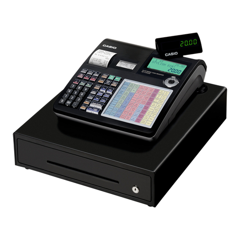
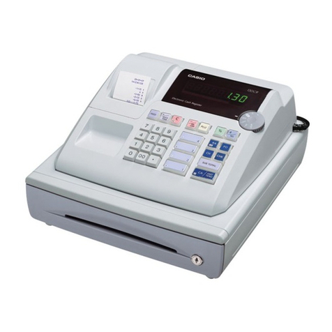
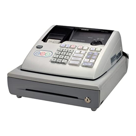
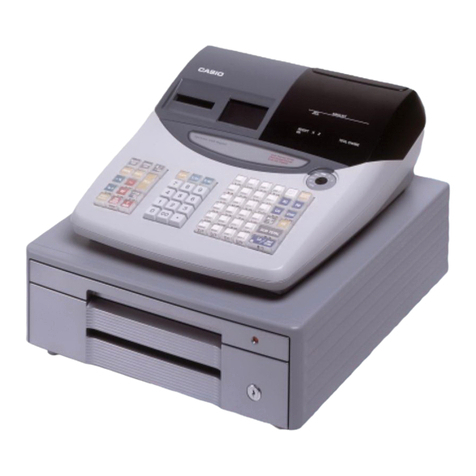
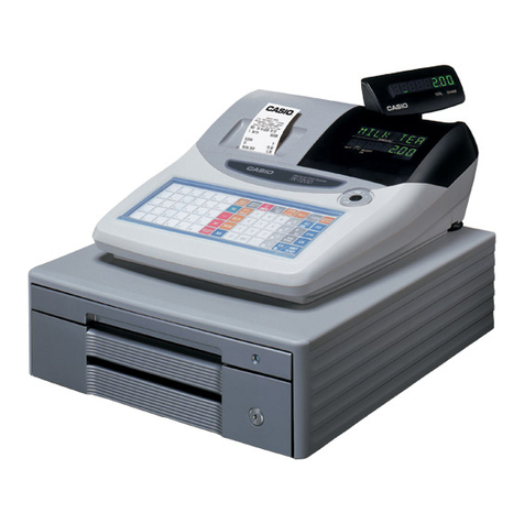
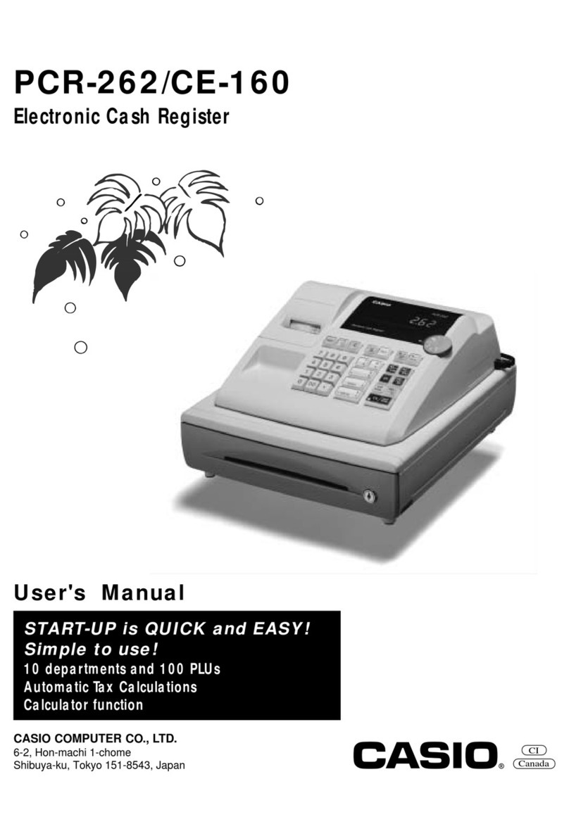
Casio 200cR User manual

SERVICE MANUAL
(without price)
ELECTRONIC CASH REGISTER
200CR/PCR-360/PCR-365(EX-245)
240CR/PCR-460(EX-246)
AUGUST 1996
Printer Model : M405R
(WHC) (OSS)

CONTENTS
1. Features ................................................................................................................... 1
2. Specifications
2-1. Electrical specifications ................................................................................. 1
2-2. Environmental specifications ........................................................................ 1
2-3. Principal components .................................................................................... 2
2-4. Option .............................................................................................................. 2
3. MAC (Memory All Clear) operation ........................................................................ 3
4. Diagnostic operation
4-1. How to start ..................................................................................................... 4
4-2. Mode switch and PAD status display check................................................. 4
4-3. Hard key code check ...................................................................................... 5
4-4. Hard check function
4-4-1. Display, RAM, drawer and printer check............................................ 5
4-4-2. Print test ............................................................................................... 6
4-4-3. Read/write test for EEPROM ............................................................... 6
4-4-4. Read test for EEPROM ........................................................................ 7
4-4-5. RAM read only check........................................................................... 7
4-4-6. Voltage check of memory back-up battery ........................................ 7
4-4-7. All characters print check ................................................................... 8
4-4-8. Display the time ................................................................................... 8
4-4-9. Country code write .............................................................................. 9
4-4-10.How to release the diagnostic mode ................................................. 9
5. Circuit explanation
5-1. Power supply circuit..................................................................................... 10
5-2. CPU (µPD78054GC)....................................................................................... 12
5-3. Mode key switch status read ....................................................................... 13
5-4. RAM address ................................................................................................. 14
5-5. Initialize IC (Reset IC) ................................................................................... 14
5-6. Data communication between CPU and EEPROM..................................... 15
5-7. Notice of display LEDs ................................................................................. 17
5-8. Display control circuit .................................................................................. 17
5-9. Printer drive circuit ....................................................................................... 18
5-10.IC data............................................................................................................ 18
5-11.Error code...................................................................................................... 20
6. How to open upper case....................................................................................... 21
7. Remove the drawer ............................................................................................... 22
8. Parts layout............................................................................................................ 23
9. Circuit diagrams .................................................................................................... 25
10. Parts list (200CR/PCR-360/PCR-365) ................................................................... 41
11. Parts list (240CR/PCR-460)................................................................................... 52
— 1 —
• Operating temperature 0 ~ 40 °C
• Operating humidity 10 ~ 90 %
• Storage temperature -25 ~ 65 °C
• Storage humidity 10 ~ 95 %
• Vibration strength 1.5 G (The machine must be in the carton box)
1. Features
The difference between 200CR and 240CR is as follows:
Function 200CR/PCR-360/PCR-365 240CR/PCR-460
POP display Nil Available
Stamp function Nil Available
Customer display Available Available
Power protection function Nil Nil
LED transaction Nil Available
EEPROM Nil Available
(except PCR-460)
Calculator function Available Available
2. Specifications (200CR/PCR-360/PCR-365/240CR/PCR-460)
2-1. Electrical specifications
(120 V) (220 V) (230 V) (240 V)
• Power consumption In operation Max. 0.25A 0.13A 0.13A 0.13A
Min. 0.10A 0.05A 0.05A 0.05A
MODE SW off 0.10A 0.04A 0.04A 0.04A
• Memory protection Back-up battery Mangan battery (UM-3 x 3 pcs.)
Back-up period 1 year (25°C)
Battery life Replace the battery every year.
• Clock & Calendar Accuracy Within ±30 sec. per month (25°C)
Auto calendar Effective until 2099A.D.
2-2. Environmental specifications

— 2 —
• CPU Name µPD78054GC-213-3B9 (200CR etc.)
µPD78054GC-214-3B9 (240CR etc.)
Number of control bit 8
Internal RAM 1024 B
Internal ROM 32 KB
Main system clock 5.00 MHz
Sub system clock 32.768 KHz
• RAM Name LC3564S70/85/10
Capacity 8 KB
Name CXK58257AP-70/10L
Capacity 32 KB (PCR-460 only)
• Printer Name M-405R
Print method Print wheel selective system
Print digit 12 digits ( Numeric : 10 digits
Symbol : 2 digits)
Printing speed Approx. 3 lines/sec.
MCBF 1,000,000 lines
Paper width W 57.5 ±0.5 mm
Paper diameter 80 mm or less
Paper thickness 0.06 ~ 0.085 mm
Ink ribbon RAP-01
Ribbon life 50,000 lines
• Display Name LED (HDSP-5621-G or HDSP-5621-H)
Number of digit 8 digits (LED x 4 pcs.)
• Power transformer Name TE-240-E4D (US, Canada)
TE-240-E3U (Except US, Canada)
• Keyboard Input system 2 keys roll over / 6 keys buffer memory
• Drawer 200CR DL-1320 for U.S.
PCR-360/PCR-365 DL-2762 for Canada, other countries.
240CR DL-1320 for US
PCR-460 DL-1832 for Europe, other countries.
DL-2762 for Europe, UK, Germany other
countries.
2-3. Principal components
2-4. Option
• Wet cover Name WT-73

— 3 —
3. Mac (Memory All Clear) operation
Procedure A
(1) Plug the power cord into an outlet.
(2) Pressing the FEED button and turn the mode switch to PRG position.
(3) Release the FEED button. After few seconds, MAC operation will be executed.
(4) The following receipt will be issued, if completed.
Procedure B
(1) Remove the power cord from AC outlet.
(2) Remove the memory protection batterey.
(3) Leave the machine for few minutes.
(4) Plug the power cord to AC outlet and then MAC operation is executed.
(5) Set the memory protection battery.
00—00—00 Date
00—00 Time
0001 Consecutive No.
• 2 7 4 8 • 1 ROM version No.
0000000000 MAC print

— 4 —
4. Diagnostic operation
4-1. How to start
(1) Plug the power cord into an outlet.
(2) Execute the MAC operation.
(3) Turn the mode switch to “PRG” position.
(4) Input 99990000 and press the sub total button.
(5) Start the diagnostic program and issues the following receipt.
Note : If you have done the registration after MAC operation, the Diagnostic program can not start.
4-2. Mode switch and PAD status display check
When the Clear key is pressed or changing the position of mode switch, the machine displays the
mode switch position.
00-00-00
00-00
0001
XXXX N1N2N3
99990000
XXXX : Version No.
N1 : 1 : Export (ADD:2)
2:US
3 : Export (ADD:0)
5 : Canada
6 : Export (ADD:1)
N2 : Blank : Export
N3 : 0 : PCR-365
1 : PCR-360
Blank : Except Above model
0 Open: US/Canada
1 Short: Except US/Canada
1 PRG
2RF
3 REG
4 CAL
5X
6Z
0 OFF
1
PAD2 condition
PAD1 condition
MODE SW position
0 Open
1 Short
0 Open: US
1 Short: Canada
PAD3 condition
PCR-360 (WHC) is displayed "0".
PCR-365 (OSS) is displayed "1".
PCR-460/240CR is displayed "0".

— 5 —
4-3. Hard key code check
When all keys except numerical keys, Clear key and FEED keys are pressed directly, the machine
displays the hard key code as shown below.
Hard key code (2 digits)
Hard key code table
Hard key code
055
047 041 035 029 023 017
FEED
055 051 7 8 9 046 040 034 028 022 016
058 054 050 4 5 6 045 039 033 027 021 015
057 053 049 1 2 3 044 038 032 026 020 014
056 052 C 0 011 012 043 037 031 025 019 013
026, 020 are effected for ST.
4-4. Hard check function
Enter 1 digit from numeral key and press the sub total (ST), the following Hard check function will
be executed.
(1) 1+ST : Display, RAM, Drawer, Printer test
(2) 2+ST : Print test
(3) 3+ST : Read/Write test for EEPROM
(4) 4+ST : Read test for EEPROM
(5) 5+ST : RAM read test
(6) 7+ST : Voltage check for memory protection battery
(7) 8+ST : Print all characters
(8) 9+ST : Display the time
(9) 6+ST : Country code write to EEPROM
4-4-1. Display, RAM, drawer and printer check
Operation : 1+ST
1) All segments turn on.
2) Date and time set.
Date : 31st December 1995
Time : 23 : 59 : 00 P.M.
Above conditions are automatically set on the machine.
8. 8. 8. 8. 8. 8. 8. 8.

— 6 —
3) RAM write and read check
The machine writes data into RAM and read out the data to compare with written data.
When this check is finished correctly, the machine goes to check No. 4).
However, if an error is occurred, the machine sounds an error tone, prints the error receipt,
and stops Hard check program.
Error receipt sample " — — — — — — — 2"
4) Drawer open check
5) Receipt issue
6) Test character print
1234567890 CATL
7) Test display
123456.78
Note : Decimal point on the display depends on the PAD condition.
4-4-2. Print test
Operation : 2+ST
Prints the following character continuously.
To stop this test, press any key or turn the mode switch to "OFF" position.
Printing speed
45 times / Min.
Print character
Note: In case press " 12 + ST ", the following test is executed.
Printing speed: 25 times / Min.
Drawer open : 5 times / Min.
Stamp print: 5 times / Min.
• 88 • 88

— 7 —
4-4-3. Read/write test for EEPROM
Operation : 3+ST
Execute the Read/write test in test area (1word) of EEPROM.
Note: This test is effected on 240CR only.
If an error is occurred, the machine sounds an error tone, prints " — — — — — — — 8"
on receipt, and stops this test.
4-4-4. Read test for EEPROM
Operation : 4+ST
The machine reads out the data to compare with written data until an error is occurred and
brinks "—" on the display during this test.
Notes: This test is effected on 240CR only.
If an error is occurred, the machine sounds an error tone, prints " — — — — — — — 8"
on receipt, and stops this test.
To stop this test, turn the Mode Switch to “OFF” position.
Be sure to execute the Read/write test for EEPROM (3+ST) before this test.
4-4-5. RAM read only check
Operation : 5+ST
Note: Be sure to execute the RAM write and read check (1 + ST) before this check.
The machine reads out the data to compare with written data until an error is occurred and
brinks " — " on the display during this check.
To stop this check, turn the mode switch to OFF position.
If an error is occurred, the machine sounds an error tone, prints " — — — — — — — 2" on
the receipt, and stops this check.
4-4-6. Voltage check of memory back-up battery
Operation : 7+ST
Display the voltage of back-up battery in real time. (Measurement is Volt (V) level.)
To stop this check, press any key or turn the mode switch to OFF position.
In case the voltage level is less than 3 V, display "L" here.
Voltage level
XXX L
➞

— 8 —
4-4-7. All characters print check
Operation : 8+ST
0 000000000 CA TL
1 111111111 CH AT
2 222222222 RC CK
3 333333333 PD TA
4 444444444 NT TX
5 555555555 ST No
6 666666666 I+
7 777777777 II -
8 888888888 III RF
9 999999999 CG @
. ......... X✽VD
- --------- Z% #
Note: In case press " 1 8 + ST ", prints all characters continuously.
To stop this test, turn the mode switch to "OFF" position.
4-4-8. Display the time
Operation : 9+ST
The machine display the time.
To stop this check, press any key.
2 3 — 5 9 01 The time counts up.

— 9 —
Code Country
1 Export (ADD2)
2 U.S.
(
*
)
3 Export (ADD0)
5 Canada
(
*
)
6 Export (ADD1)
9 Erase only
(
*
)
: It is no effect because of no EEPROM .
Normal receipt
XXXX N1N2N3
XXXX: Version No.
N1 : 1 : Export (ADD2)
2 : U.S.
3 : Export (ADD0)
5 : Canada
6 : Export (ADD1)
N2 : Blank:Export
N3 : 0 : PCR-365(OSS)
1 : PCR-360(WHC)
Blank : Except the aboves.
< Country code >
4-4-9. Country code write
Operation : X 6+ST
X:Country code
Erase the EEPROM and write the country code into EEPROM.
Note: This test is effected on 240CR only.
If an error is occurred, the machine sounds an eror tone, prints " — — — — — — — 8" on the
receipt.
4-4-10. How to release the diagnostic mode
Make MAC operation.

— 10 —
5. Circuit explanation
5-1. Power supply circuit
Q1 : Transistor for controlling voltage (VP)
Q1 : Transistor for voltage detection
Q3 : Transistor for controlling power down (PWD) signal
ZD2 : Zenner diode for controlling base current of Q2
ZD1 : Zenner diode for detecting power down (PWD) signal
After plug the AC cord into the outlet, the 24 volts of AC voltage appears between T1 and T2.
Then this voltage is rectified by the diode bridge and it become constant voltage through the
capacitor C1.
[Voltage VP]
A constant voltage (17.9V) appears on the C point. This voltage made from the constant voltage
circuit consist of transistor Q1 and Q2, zenner diode ZD2, resistor R2, R3, R4 and R5.
[Voltage VLED and VCC]
The voltage goes to 1 pin of regurator IC1 from B point and out from 2 pin of IC1 as stable voltage
5.5 volts. Then this voltage down to 5 volts through the diode.
It is used for VCC (for logic) and VLED (for display drive).
Also, it goes to 4 pin of IC1 and using to control the output voltage of 2 pin.
Capacitor C5 is used to reduce the ripple of this voltage.
Inductor L1 is used to stabilize the VCC voltage when the drawer opend.
2
1
5277-02A
CN1
TRANS
F1
PWD
C1
50F2S683J
C2
ZD2
ZD1
RD13EB3
R5
R1 560
2.2K
RD5.6EB3 R3 3.9K
35V3300 R4
R50X-2K
1SR35-100A
D2
D5
1SR35-100A
1SR35-100A
D4
1SR35-100A
D3
C6
25V33
C5
D1 1S2473
D6 1S2473
D7 RK-14
25V330
C3
GND
35V47
Q1
WITH HEAT-SINK
D1276A
R2 1.2K
Q2
C945
R7 Q3
R9
10K VDD
LM2575T-5.0
VIN1 VIN VOUT
L331KL1
IC1
3
GND
5
2
4
ON/OFF
OUTPUT
FEED BACK
C945
D8
1S2473
4.7K
GND
D10 1S2473
VP
VLED
VCC
J
K
A
B
D
I
C
H
FG
E

— 11 —
[PWD signal]
After plug the AC cord into outlet, VP voltage appears on the base terminal of transistor Q3.
When the VP exceeds 13 volts, Q3 is turned on by the differential voltage between base and
emitter of Q3.
Then the PWD signal goes to GND level and informs "power on" to the CPU.
When the VP drops less than 13 volts, Q10 is turned off.
Then the PWD goes high level since the PWD is pulled up to VDD and makes the CPU go "Power
failure process".
Note : During plug the AC cord into outlet, all voltages are supplied to the PCB.
If you open the machine for repair, make sure plug off.
[Voltage and check points in the power supply circuit]
Actual value on the E245-1 PCB [unit : V]
Check point A B C D E F G H I J K
Power on 23.2 V 30 17.9 19 5.9 6.5 4.3 0.0 0 5.6 4.8
(AC)
Voltage check position
BC DE F I
G
H
J
K

— 12 —
5-2. CPU (µPD78054GC)
Pin No. Signal Description In / Out PW-ON
level
1 P15 Head drive signal (HD1) Out Low
2 P16 Stamp drive signal (STAMP) Out Low
3 P17 Winder motor drive signal (WINDER) Out Low
4 AVss Analong ground for A/D converter — GND
5 P130 Motor drive signal (MOTOR) Out Low
6 P131 Drawer drive signal (DRW) Out Low
7 AVREF1 Standard voltage for D/A converter (VDD) — 5V
8 P70 Head drive signal (HD3) Out Low
9 P71 Head drive signal (HD4) Out Low
10 P72 Head drive signal (HD5) Out Low
11 P20 Head drive signal (HD6) Out Low
12 P21 Head drive signal (HD7) Out Low
13 P22 Head drive signal (HD8) Out Low
14 P23 Head drive signal (HD9) Out Low
15 P24 Head drive signal (HD10) Out Low
16 P25 Head drive signal (HD11) Out Low
17 P26 Head drive signal (HD12) Out Low
18 P27 Head drive signal (HD13) Out Low
19 P40 Address / Data bus (AD0) In / Out High
20 P41 Address / Data bus (AD1) In / Out High
21 P42 Address / Data bus (AD2) In / Out High
22 P43 Address / Data bus (AD3) In / Out High
23 P44 Address / Data bus (AD4) In / Out High
24 P45 Address / Data bus (AD5) In / Out High
25 P46 Address / Data bus (AD6) In / Out High
26 P47 Address / Data bus (AD7) In / Out High
27 P50 Address signal (A8) Out Low
28 P51 Address signal (A9) Out Low
29 P52 Address signal (A10) Out Low
30 P53 Address signal (A11) / Data signal from EEPROM (DO) In / Out Low
31 P54 Address signal (A12) / Data signal to EEPROM (DI) Out Low
32 P55 Address signal (A13) / Clock signal for EEPROM (SK) Out Low
33 VSS Ground — GND
34 P56 Chip enable signal for EEPROM (EEPROM CE) Out Low
35 P57 Chip enable signal for RAM (RAM CE) Out High
36 P60 Key input signal (KI0) In High
37 P61 Key input signal (KI1) In High
38 P62 Key input signal (KI2) In High
39 P63 Key input signal (KI3) In High
40 P64 Read signal for RAM (RD) Out High
41 P65 Write signal for RAM (WR) Out High
42 P66 Key input signal (KI4) In High
43 P67 Address strobe signal (ASTB) Out Low
44 P30 Display segment signal (SEG1a) / Key common singnal (KC11) Out Pulse
45 P31 Display segment signal (SEG1b) / Key common singnal (KC10) Out Pulse
46 P32 Display segment signal (SEG1c) / Key common singnal (KC9) Out Pulse
47 P33 Display segment signal (SEG1d) / Key common singnal (KC8) Out Pulse
48 P34 Display segment signal (SEG1e) / Key common singnal (KC7) Out Pulse
49 P35 Display segment signal (SEG1f) / Key common singnal (KC6) Out Pulse
50 P36 Buzzer signal (BUZZ) Out Low
51 P37 Display segment signal (SEG1g) Out Low
52 P120 Display segment signal (SEG0a) / Key common singnal (KC5) Out Pulse
53 P121 Display segment signal (SEG0b) / Key common singnal (KC4) Out Pulse
54 P122 Display segment signal (SEG0c) / Key common singnal (KC3) Out Pulse
— 13 —
Mode OFF¤ OFF (pin No. 78 of CPU)
Voltage 0 5
Mode PRG RF REG CAL X Z
Voltage (V) 4.0 3.3 2.4 1.7 0.9 0.1
except
Pin No. Signal Description In / Out PW-ON
level
55 P123 Display segment signal (SEG0d) / Key common singnal (KC2) Out Pulse
56 P124 Display segment signal (SEG0e ) / Key common singnal (KC1) Out Pulse
57 P125 Display segment signal (SEG0f) / Key common singnal ( KC0) Out Pulse
58 P126 Display segment signal (SEG0DP) Out Pulse
59 P127 Display segment signal (SEG0g) Out Low
60 RESET Reset signal (RESET) In High
61 P00 Timing pulse from printer (TP) In High
62 P01 TAX switch (TAX-SW ) / PAD condition signal (PAD2) In Low
63 P02 Power down signal (PWD) In Low
64 P03 Display common signal (DG1) Out Pulse
65 P04 Display common signal (DG2) Out Pulse
66 P05 Display common signal (DG3) Out Pulse
67 P06 Display common signal (DG4) Out Pulse
68 VDD VDD terminal (VDD) — 4.5 V
69 X1 Main system clock signal (5.00 MHz) In Pulse
70 X2 Main system clock signal (5.00 MHz) In Pulse
71 IC Vss (GND) — GND
72 XT2 Sub system clock signal (32.768 kHz) In Pulse
73 XT1 Sub system clock signal (32.768 kHz) In Pulse
74 AVDD Power for A/D converter (VDD) — 5 V
75 AVREF0 Standard voltage for A/D converter (VCC) — 5 V
76 P10 Low battery signal (LOW-BATT) In High
77 P11 Mode key condition signal (MODE) In 2.4 V
78 P12 OFF signal of mode switch (OFF-MODE IN) In High
79 P13 PAD condition signal (PAD1) In Low
80 P14 Display segment signal (SEGTR ) / PAD condition signal (PAD3) In / Out Pulse
Note : The "PW-on level" was measured under the following conditions.
Mode switch is REG position.
5-3. Mode key switch status read
The CPU knows the mode swithc status by voltage level of 1 pin No. 77.
The voltage level is down by resistor. Each voltage is as shown bleow.
Voltage level (pin No. 77 of CPU)
20Kq
OFF
To pin No.77
To pin No.78
8.2Kq
3.9Kq
2Kq
820q
PRG
RF
REG
CAL
X
Z
→

— 14 —
5-4. RAM address
CPU is used port 40 ~ 47 (pin No. 19 ~ 26) for address/data bus.
CPU sends the addressA0 ~A13 to RAM through the IC5. To select the addressA0 ~A7, CPU send
the addressAD0 ~ AD7 to IC5. Then CPU sendsASTB (Latch enable) signal to IC5.
IC5 outputs the address A0 ~A7 after receipt of ASTB signal.
GND
VDD
1 2
3
CPU
RESET
5-5. Initialize IC (Reset IC)
When the voltage level on 60 pin of CPU is not stabilized, CPU doesn’t work properly in rare case.
Therefore, this machine uses the initialize IC for stabilizing the voltage.
Even the voltage level of VDD (2 pin) is changed, 1 pin of initialize IC outputs stabilized 5 volts.
CPU
IC5
74HC373
A0 ~ A7
D0 ~ D7
AD0 ~ AD7 A8 ~ A13
ASTB
RAM

— 15 —
5-6. Data communication between CPU and EEPROM
CS : Chip enable
SK : Serial data clock
DI : Serial data input
DO : Serial data output
EEPROM is a memory to possible write/erase by electricity .
The BR93LC66A privides efficient nonvolatile read/write memory arranged as 64 registers of 16
bits each.
[Block diagram]
Command code
controller
Clock generator
Power detection
Write
protection High voltage
genarator
Address
decorder
R/W
amplifier
Address
buffer
Data
register
Dammy bit
Command
register
1024 bit
EEPROM array
SK
CS
DI
DO
6 bits
6 bits
16 bits
16 bits
1024 bits
1
2
3
4
CS
SK
DI
DO
Pin No.23
Pin No.14
Pin No.15
Pin No.16
EEPROMCPU
BR93LC46A
BR93LC66A
34
32
31
30

— 16 —
[Data reading procedure]
When the CPU read the dara of EEPROM, CPU send the CS signal and SK signal to EEPROM.
Then, CPU send the address to EEPROM, and then EEPROM send the data to CPU.
[Data writing procedure]
When the CPU save the data to EEPROM, CPU sends the CS and SK signal to EEPROM.
And CPU send the address and data to EEPROM from pin No.31.
When the EEPROM writes the data , EEPROM outputs the busy signal from DO terminal to CPU.
After finish writing, EEPROM outputs the ready signal from DO terminal to CPU.
CS
SK
DI
DO
Address
Data
Output data here
CS
SK
DI
DO
Address Data
High Impedance BUSY(L)
READY(H)
Status
CS
SK
DI
DO
CS
SK
DI
DO
Address
Data
Output data here
Address Data

— 17 —
5-7. Notice of display LEDs
This machine is using display LED.
Specification of original LED is HDSP-5621#S202.
The following LEDs are interchangeable parts. However, its brightness is different.
If you replace it for repair, use the same specification.
Specification is written here.
Specification Parts Code
HDSP-5621#S02 2320 1365
HDSP-5621 hp029 H4 2320 1368
HDSP-5621 hp029 G4 2320 1367
H type LED is a little bit brighter than G type.
Specification is written on the top of parts.
COM0
COM1
COM2
COM3
SA1 ~ SG1
SA0 ~ SG0
SDP0
5-8. Display control circuit
SEG0
SEG1
DG1 ~ DG4 COM0 ~ COM3
SA0 ~ SG0
SA1 ~ SG1
CPU
To display PCB
(E240-E2)
SA
SG
SD
SF SB
SC
SDP
SE

— 18 —
"L"→"H" "H"→"L"
"L"→"H" "L"→"H"
HD1 ~ HD13 HD1 ~ HD13
CPU
Head drive
circuit
VP
HDCOM Printer
M405R
Motor
COMVP
Motor drive
circuit
MotorMotor
5-9. Printer drive circuit
When CPU wants to rotate the mortor, CPU outputs “Motor” signal (L ➔H), and Motor signal goes
through the motor drive circuit and then it become “L”.Then Motor rotates because of difference voltage
between Motor and Motor COM TERMINAL.
Head drive signal is same as Motor drive.
IN1 1 16 OUT1
IN2 2 15 OUT2
IN3 3 14 OUT3
IN4 4 13 OUT4
IN5 5 12 OUT5
IN6 6 11 OUT6
IN7 7 10 OUT7
GND 8 9 COM
NC
A12
A7
A6
A5
A4
A3
A2
A1
A0
I/O 1
I/O 2
I/O 3
GND
Vcc
WE
CE2
A8
A9
A11
OE
A10
CE1
I/O 8
I/O 7
I/O 6
I/O 5
I/O 4
TOP VIEW
1
2
3
4
5
6
7
8
9
10
11
12
13
14
28
27
26
25
24
23
22
21
20
19
18
17
16
15
5-10. IC data
1. BA12001/BA12004 2. LC3654
A0 ~ A12 : Address
WE : Write enable
CE1 : Chip enable 1
CE2 : Chip enable 2
I/O1 ~ I/O8 : Data
Vcc/GND : Power terminal
Other manuals for 200cR
1
This manual suits for next models
4
Table of contents
Other Casio Cash Register manuals

Casio
Casio TK-6500 Series User manual

Casio
Casio SE-C300 User manual

Casio
Casio PCR-210 Assembly instructions

Casio
Casio QT-6000 User manual

Casio
Casio SE-S100 User manual

Casio
Casio 120CR User manual

Casio
Casio 120CR User manual

Casio
Casio SE-C3500 User manual

Casio
Casio TE-M80 User manual

Casio
Casio PCR-T2100 User manual

Casio
Casio CE-6100 User manual

Casio
Casio QT-6100 User manual

Casio
Casio CE-7000 User manual

Casio
Casio QT-6100 User manual

Casio
Casio E-63ER Assembly instructions

Casio
Casio SE-C2000 User manual

Casio
Casio SR-C550 User manual

Casio
Casio TK-T200 User manual

Casio
Casio CE-2400 Assembly instructions

Casio
Casio SE-G1 User manual