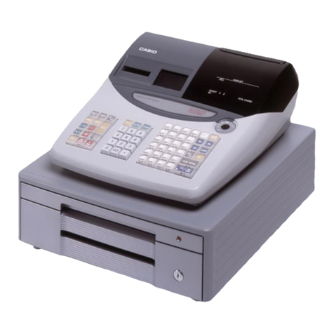
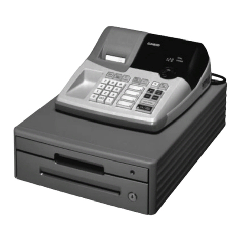
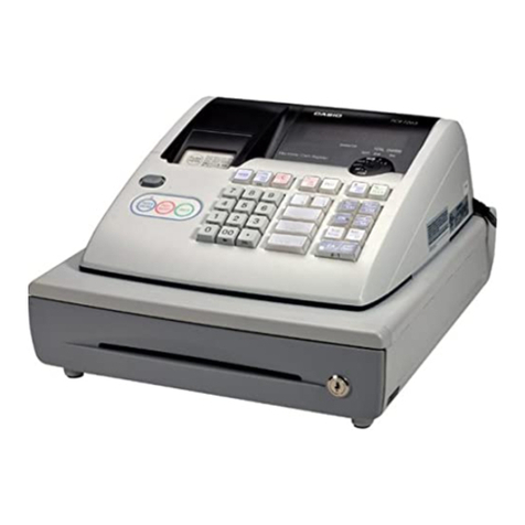
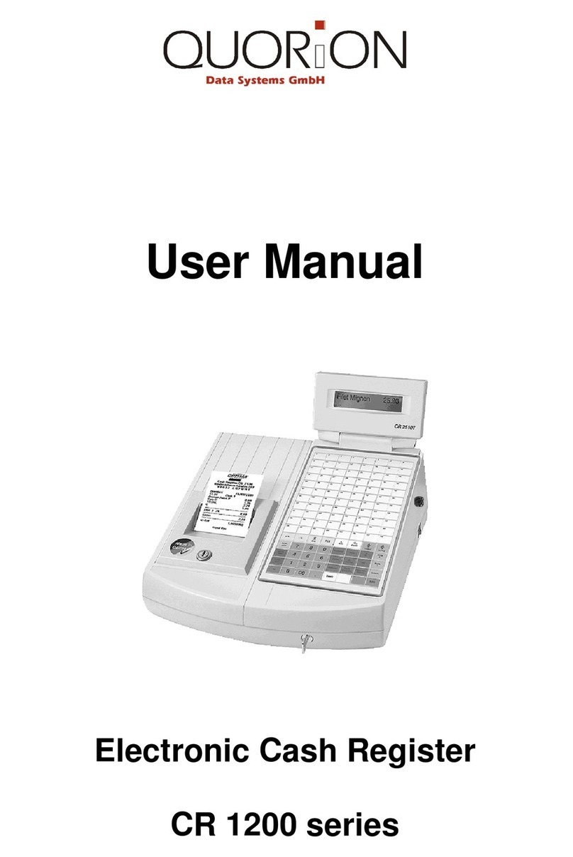
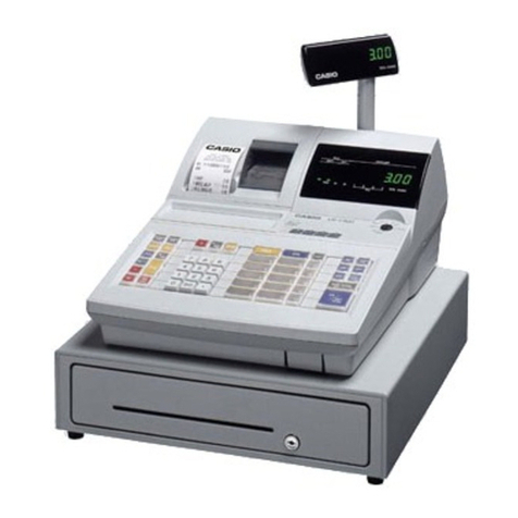
Casio FE-700 MEX User manual

SERVICE MANUAL
(without price)
ELECTRONIC CASH REGISTER
FE-700 MEX (EX-287 Mexican Version)
Jan. 2003
Printer model : M190G
(without price)
FE-700
FE-700
0.00
0.00
INDEX

CONTENTS
FE-700 Page
1. SPECIFICATIONS........................................................................................ 1
2. INITIALIZE (MAC) OPERATION.................................................................. 2
3. F-INIT (FMAC) OPERATION ....................................................................... 2
4. BLOCK DIAGRAM....................................................................................... 3
4-1. PCB CONNECTION.............................................................................. 3
4-2. BLOCK DIAGRAM (CIRCUIT).............................................................. 4
5. DISASSEMBLY (FE-700)............................................................................. 5
5-1. MAIN PARTS ........................................................................................ 5
6. CIRCUIT EXPLANATION ............................................................................ 8
6-1. Power supply circuit ........................................................................... 8
6-2. CPU (IC11: uPD78052GC-A46-8BT) ................................................... 9
6-3. Display controller (IC2: uPD16312GB-3B4)..................................... 11
6-4. Initilize IC (Reset circuit)................................................................... 12
6-5. Power down detection circuit (PWD)............................................... 12
6-6. Address latch circuit ......................................................................... 12
6-7. RAM / ROM / Fiscal ROM bank selection circuit............................. 13
6-8. Fiscal ROM address and data selection.......................................... 14
6-9. Head drive circuit for printer ............................................................ 15
6-10. VPP sensor circuit........................................................................... 16
6-11. Power supply circuit for display ................................................... 17
7. DIAGNOSTIC ............................................................................................. 18
7-1. To start the diagnostic program ...................................................... 18
7-2. Check item ......................................................................................... 18
7-3. Operation of each test....................................................................... 18
7-4. Switch status test .............................................................................. 19
7-5. Individual function test ..................................................................... 20
7-6. Fiscal ROM test.................................................................................. 23
7-7. To exit the diagnostic test ................................................................ 23
8. ERROR CODE ........................................................................................... 24
8-1. Operation error code......................................................................... 24
8-2. Fiscal ROM error code ...................................................................... 25
8-3. System lock code .............................................................................. 26
9. IC DATA ..................................................................................................... 27
10. PCB LAYOUT ............................................................................................ 32
11. CIRCUIT DIAGRAM ................................................................................... 33
12. PARTS LIST............................................................................................... 50

— 1 —
1. SPECIFICATIONS
Power consumption In operation Max 30W
Standby 11W
Mode SW OFF 7W
Memory protection Backup battery Vanadium Lithium secondary battery
VL3032/1F2
Back up period 90 days (25°C)
Battery life 5 years (25°C)
Recharge time 48 hours
Memory capacity 1Mbits uPD431000ACZ-70LL
Clock and calender Accuracy Within ±30 sec. per month(25˚C)
Auto calender Effective until 2099 A.D.
Environment Operating temperature 0°C ~ 40°C
Operating humidity 10% ~ 90%
Storage temperature -25°C ~ 65°C
Storage humidity 10% ~ 95%
Printer Model M-190G(071)
Print method Dot matrix printing
MCBF 1,500,000 lines
Life 2,500,000 lines
(Motor,Head unit,Cam trigger set, etc.)
Ink cassette Model ERC-40P
Life About 2,000,000 charactors
Roll paper Type Fine-quality paper
or Pressure-sensitive copy paper
Size 57.5±0.5 mm
Roll diameter 80 mm or less
Paper thickness Upper : 0.066mm
Lower : 0.058mm

— 2 —
2. INITIALIZE (MAC) OPERATION
1. Set the mode switch to "OFF" position.
2. Press the "INIT SW".
3. Turn the mode switch to ""REG" (Except "OFF" or "Z") position.
4. Release the "INIT SW" .
5. Input the MAC CODE. (10 digits)
6. Press "#2" key.
7. Initialize operation is executed.
MAC CODE : D1 to D10 (10 digits)
D1 to D6 : Date input data (DD-MM-YY) Note: YY= 00 (2000) to 99 (2099)
D7 to D9 : Any number input digit.(exp : 000)
D10 :select figure break point symbol (1:"." , 2: "," )
NOTE: In case the ECR works abruptly caused cange ROM without removing the battery,
Turn the power off and remove the battery connector then perform the MAC operation.
3. F-INIT (FMAC) OPERATION
1. Set the mode switch to "OFF" position.
2. Press the "INIT SW" .
3. Turn the mode switch to "REG" (Except "OFF" or "Z") position.
4. Release the "INIT SW".
5. Press "#2" key.
Note : The location of "#2" key, see "HARD KEY CODE TABLE" on page 18.
INIT SW

— 3 —
4. BLOCK DIAGRAM
4-1. PCB CONNECTION

— 4 —
4-2. BLOCK DIAGRAM (CIRCUIT)
MAIN DISPLA
SH101MAY
CUSTOMER DISPLAY
SH101MA
Segment & Digit data
Sensor signal
uPD16312GB-3B4 DRWS
PNES
Mode
Key
Keyboard
FPC
FISCAL ROM
D0~D7
A0~A7
A8~A15
A8~A15
AD0~AD7
ROM
RAM
AD0~AD7
Address data bus
A0~A7
MD
Reset circuit
S80719AN
Head drive cuicuit
HD.A~HD.H
PWD detection
VPP sensor circuit
RS232C circuit
DI,DO,CLK,STB
FB0~FB5
KC0~KC4
AD0~AD5
Select addess
Printer
M190G
FD
CPU
uPD78052G-A46-8BT

— 5 —
5.DISASSEMBLY (FE-700)
5-1.MAIN PARTS
1.Open the printer cover.
Remove the 2 screws of the upper case.
2.Slide the upper case to the front side.
3.Open upper case from the left side.
4.The battery is located at the printer fixing stand.
Remove the 2 screws.
Battery VL3032/1F2

— 6 —
5. Release the hook them Remove the write side.
6. Release 3screws to remove printer plastic stand.
7. Release 2screws to remove printer unit.
8. Release 1 screw to remove display case.
Remove 1 screw.
Hook
Remove the 4 screws.
Remove the 2 screws.

— 7 —
9. Lift up upper case.
10. To remove the main PCB, release 7 screws and
2 screws for the COM port.
Remove the 7 screws.
Remove the 2 screws for the COM port.

— 8 —
6.CIRCUIT EXPLANATION
6-1. Power supply circuit
Q1 : Power transistor
Q2 : Voltage detection transistor
Voltage level at above check point (unit : V )
Measurement
position ABCD
Voltage (V) 12.5V 5.3V 6.2V 2 .47V
AB
C
D

— 9 —
6-2. CPU (IC11: uPD78052GC-A46-8BT)
Pin No. Signal Description In/Out Status of Status of
Power On Power OFF
1 FB3 Fiscal ROM bank 3 Out High High
2 FB4 Fiscal ROM bank 4 / RAM bank 3 Out High High
3 FB5 Fiscal ROM bank 5 / RAM bank 4 Out High High
4 AVSS GND - GND GND
5 PGM PRG signal for Fiscal ROM Out High High
6 RAM RAM disable Out High Low
7 AVREF VDD - 5V 5V
8 RXD Receive data In High High
9 TXD Send data Out High High
10 WD Winder motor drive signal Out Low Low
11 DI Data signal from uPD16312 In Pulse High
12 DO Data signal to uPD16312 Out Pulse High
13 CLK Clock signal for uPD16312 Out Pulse High
14 STB Data strobe signal for uPD16312 Out Pulse High
15 KC0 Key common signal (KC0) Out Pulse High
16 KC1 Key common signal (KC1) Out Pulse High
17 KC2 Key common signal (KC2) Out Pulse High
18 KC3 Key common signal (KC3) Out Pulse High
19 AD0 Address / Data signal (AD0) In/Out Pulse High
20 AD1 Address / Data signal (AD1) In/Out Pulse High
21 AD2 Address / Data signal (AD2) In/Out Pulse High
22 AD3 Address / Data signal (AD3) In/Out Pulse High
23 AD4 Address / Data signal (AD4) In/Out Pulse High
24 AD5 Address / Data signal (AD5) In/Out Pulse High
25 AD6 Address / Data signal (AD6) In/Out Pulse High
26 AD7 Address / Data signal (AD7) In/Out Pulse High
27 A8 Address signal (A8) Out Pulse High
28 A9 Address signal (A9) Out Pulse High
29 A10 Address signal (A10) Out Pulse High
30 A11 Address signal (A11) Out Pulse High
31 A12 Address signal (A12) Out Pulse High
32 A13 Address signal (A13) Out Pulse High
33 VSS GND - GND GND
34 A14 Address signal (A14) Out Pulse High
35 A15 Address signal (A15) Out Pulse High
36 INIT INIT switch signal In Low Low
37 VPP VPP OUT signal Out High High
38 DSR Data set ready signal In High High
39 KC4 Key common signal (KC4) Out Pulse High
40 RD Output enable signal of RAM/ROM (RD) Out Pulse High
41 WR Write enable signal of RAM (WR) Out Pulse High
42 RA14 Address signal of ROM (Bank 0) Out High High
43 ASTB Latch enable for Addres decoder (ASTB) Out Pulse Low
44 KI12 Key input signal (KI12) In High High
45 KI13 Key input signal (KI3) In High High
46 RA16 Address signal of ROM (Bank2) Out High High
47 RA15 Address signal of ROM (Bank 1) Out High High
48 MD Motor drive signal of printer (MD) Out Low Low
49 DRW Drawer drive signal (DRW) Out Low Low
50 BUZ Buzzer signal (BUZZ) Out Low Low
51 FD Paper feed signal of printer (FD) Out Low Low
52 HD.A Head drive signal of printer (HD.A) Out Low Low
53 HD.B Head drive signal of printer (HD.B) Out Low Low
54 HD.C Head drive signal of printer (HD.C) Out Low Low
55 HD.D Head drive signal of printer (HD.D) Out Low Low

—10 —
Pin No. Signal Description In/Out Status of Status of
Power On Power OFF
56 HD.E Head drive signal of printer (HD.E) Out Low Low
57 HD.F Head drive signal of printer (HD.F) Out Low Low
58 HD.G Head drive signal of printer (HD.G) Out Low Low
59 HD.H Head drive signal of printer (HD.H) Out Low Low
60 RESET Reset signal (RESET) In High High
61 DP Dot pulse form printer (DP) In Low High
62 RP Reset pulse from printer (RP) In High High
63 OFF Mode key status (OFF) Out High Low
64 PWD Power down signal (PWD) In Low High
65 RB0 Address signal for RAM (Bank 0) Out High High
66 RB1 Address signal for RAM (Bank 1) Out High High
67 RB2 Address signal for RAM (Bank 2) Out High High
68 VDD VDD - 5V 5V
69 X2 System clock ( 5MHz) In Pulse High
70 X1 System clock ( 5MHz) In Pulse High
71 IC GND - GND GND
72 XT2 Sub system clock (32.768KHz) In Pulse Pulse
73 XT1 Sub system clock (32.768KHz) In Pulse Pulse
74 AVDD VDD - 5V 5V
75 AVREF0 VCC - GND GND
76 VPP.S VPP detection signal (VPP.S) In Low Low
77 BAT Non connection - High High
78 FB0 Address signal of Fiscal ROM bank 0 Out High High
79 FB1 Address signal of Fiscal ROM bank 1 Out High High
80 FB2 Address signal of Fiscal ROM bank 2 Out High High

—11 —
6-3. Display controller (IC2: uPD16312GB-3B4)
Pin No. Signal Description In/Out Status of Status of
Power On Power OFF
1 SW1 Not used (GND) - GND GND
2 SW2 Not used (GND) - GND GND
3 SW3 Not used (GND) - GND GND
4 SW4 Not used (GND) - GND GND
5 DOUT Data out signal to CPU Out High High
6 DIN Data in signal from CPU In Pulse High
7 VSS GND - GND GND
8 CLK Clock signal (CLK) In Pulse High
9 STB Data strobe signal (STB) In Pulse High
10 KEY1 2nd display sensor signal (D.TEST1) - Low Low
11 KEY2 Peper near end sensor signal (PNES) In High High
12 KEY3 Drawer sensor signal (DRW.S) In High High
13 KEY4 VCC - 5V 5V
14 VDD VCC - 5V 5V
15 SEG1 Display segment signal (Sa) Out Pulse Low
16 SEG2 Display segment signal (Sb) Out Pulse Low
17 SEG3 Display segment signal (Sc) Out Pulse Low
18 SEG4 Display segment signal (Sd) Out Pulse Low
19 SEG5 Display segment signal (Se) Out Pulse Low
20 SEG6 Display segment signal (Sf) Out Pulse Low
21 SEG7 Display segment signal (Sg) Out Pulse Low
22 SEG8 Display segment signal (Sdp) Out Pulse Low
23 SEG9 Display segment signal (Str) Out Pulse Low
24 SEG10 Display segment common signal (Scom) Out Pulse Low
25 SEG11 Not used Low Low
26 SEG12 Not used Low Low
27 VEE Power for display (-VN) - -32V -32V
28 GRD10 Display digit signal (G10) Out Pulse Low
29 GRD9 Display digit signal (G9) Out Pulse Low
30 GRD8 Display digit signal (G8) Out Pulse Low
31 GRD7 Display digit signal (G7) Out Pulse Low
32 GRD6 Display digit signal (G6) Out Pulse Low
33 GRD5 Display digit signal (G5) Out Pulse Low
34 GRD4 Display digit signal (G4) Out Pulse Low
35 GRD3 Display digit signal (G3) Out Pulse Low
36 GRD2 Display digit signal (G2) Out Pulse Low
37 GRD1 Display digit signal (G1) Out Pulse Low
38 VDD VCC - 5V 5V
39 LED4 Not used - Pulse Low
40 LED3 Not used - Pulse Low
41 LED2 Not used - Pulse Low
42 LED1 Not used - Pulse Low
43 VSS GND - GND GND
44 OSC System clock (500KHz) In Pulse Pulse

—12 —
6-4. Initilize IC (Reset circuit)
VDD : Voltage of memory protection battery
To Pin No.60 of CPU
When the voltage level at Pin No.60 of CPU is not stabilized, CPU does not work properly
in rare case. Therefore, this machine uses the initialize IC for stabilizing the voltage.
Even the voltage lebel of VDD(Pin No.2) is changed, Pin No.1 of initilize IC outputs
stabilized 5 volts. When the VDD voltage become less than 1.9V, the initialize IC send a
reset signal to CPU.
6-5. Power down detection circuit (PWD)
To Pin No.64 of CPU
When the VP voltage become less than 4.8V, the pin No.1 of IC5 become "Low" level.
Then,the transistor Q43 become OFF.
When Q43 become OFF, the voltage lebel of pin No.64 of CPU changes to "High" level
from "Low". Then, CPU knows power failure.
6-6. Address latch circuit
CPU uses 8 port (AD0 ~ AD7) for address bus
and data bus.
To select the address, CPU use the IC13.
CPU send the address to IC13, and send ASTB
signal at same time.
Then, IC13 store the address and output the
address immediately.
In this way, CPU select the address and data
signal.

—13 —
6-7. RAM / ROM / Fiscal ROM bank selection circuit
This circuit is used for address decoder for mamory.
A11
IOGATE
GATE
F. ROM1
F.ROM2
HC32A
HC32A
HC32A
1
2
12
13
3
11
IC22
IC22
IC22
HC32A
9
10 8
IC22
GND
R123
56K
VCC
C64
100P
PGM PGM
EEPCE
9
Memory Map
C000
A000
8000
6000
4000
2000
0000
RAM BANK select
area (4K)
E000
RAM common area
(8K)
EP ROM
Common (16K)
Mask ROM
(16K)
F000
F800
Internal RAM
(High speed access)
288 bytes
Internal RAM
(High speed access)
Short direct area
192 bytes
FE20
FFFF
FA80 Internal RAM
(High speed access)
Outer I/O area
F000 General purpose
register 32 bytes
Special function
register (SFR)
256 bytes
Direct access
window for
Fiscal ROM
(2K)
FEE0
FFF0
Bank
0 Bank
5
Bank
4
Bank
2
Bank
1 Bank
3
EP ROM
Bank select area
(16K) FAE0
FD00
Buffer RAM 32 bytes FAC0
KI signal port (F800,F801)
0000000000100010 00011 00100 00101 00110
Bank
29
11101
RAM256K RAM 1M

—14 —
6-8. Fiscal ROM address and data selection
This circuit is used for interface of Fiscal ROM.
To improve the signal level of interface, this machine is used buffer IC (TC74HC367A) at
all signal lines.
IC8 is used for the gate of data bus between te Fiscal ROM and CPU.

—15 —
6-9. Head drive circuit for printer
Motor drive circuit
Normally, the transistor of motor drive circuit is followng condition.
TR1,TR2,TR5 : OFF
TR3, TR4 : ON
MD(-) signal : VP level
When the CPU want to rotate the motor, CPU change the MD signal to "High" from "Low".
Then, TR1,TR2 and TR5 are become ON and MD(-) signal is become GND level,
and then motor is rotated.
Head drive circuit
When the CPU wants to print, CPU send "High" signal from HD.A ~ HD.H terminal.
This signal goes to printer unit, and then print.
RP : Reset pulse from printer
DP : Dot pulse from printer
TR1
TR2
TR4 TR3
TR5

— 16 —
6-10. VPP sensor circuit
Normal To write the data to Fiscal ROM
VDD +5.1V +5.1V
VCC +5.1V +5.1V
FVCC +5.4V +6.5V
VPP +5.2V +13.1V
VPP.S Previous condition Inverted ( *1)
Note *1 : When the "VPP" became 13.1V, "VPP.S" level is inverted.
This circuit is using for making the voltage when the CPU write the data to Fiscal ROM.
When the CPU wants to write the data to Fiscal ROM, CPU makes the "VPP.ON" signal
to "Low level".
DCS2 (PS10017): Booster circuit ( from 5V to 13V )
IC3 (M5237L) : IC for making 5V from 13V
Each voltage level (Unit : V)

—17 —
Protection circuit
To prevent the Fiscal ROM breakage, the protection circuit watches the voltage lebel of
VCC,VDD,FVCC and VPP.
When the each voltage level is more than following condition, this circuit cuts the voltage.
VCC,VDD and FVCC : In case these voltages are become over voltage, this circuit
outputs "SCR" signal(High signal) and burn out the fuse.
VPP : In case the VPP voltage is more than 15V or less than 13.9V, the "VPP.S" level is inverted and CPU
cut the "VPP.ON" signal.
Detection voltage level (Unit : V)
VCC >= +6.5V
VDD >= +6.5V
FVCC >= +7.7V
+13.9V =< VPP <=15.0V
6-11. Power supply circuit for display
This circuit is making the power for display tube.
Voltage level : -VN Est. -31.2V
VF1 - VF2 Est. AC4.85V
GND

— 18 —
7. DIAGNOSTIC
7-1. To start the diagnostic program
1. Set the mode switch to "OFF" position.
2. While pressing the "INIT" switch, turn the mode switch to "PGM" position.
3. Release the "INIT" switch.
4. Input "9999900000" and press "ST" ("#2" key).
5. Diagnostic program is executed.
7-2. Check item
The following test can be checked in the diagnostic test.
1. Key code test
2. Switch status test
3. Individul function test
4. FISCAL ROM, Vpp test
7-3. Operation of each test
1. Key code test
When pressing a key, the machine displays
the following key code with the exception,
"FEED","C","0-9" button.
HARD KEY CODE TABLE
TMAC . . . . . . . . . . . . . . . . . . . . . XXXX
9999900000
(c) 2001 by CASIO
COMPUTER CO.,LTD.
All rights reserved.
XXXX: Version No.
Note: "026" button is work for "#2" key.
Hard key code
0 1 3
DISPLAY
1 9
FEED 055 051
054 050
053 049
052 C
789
456
123
0011 012
046 040
045 039
044 038
043 037
028 022
027 021
026
(#2)
025
Table of contents
Other Casio Cash Register manuals

Casio
Casio PCR-T465 User manual

Casio
Casio 240CR Parts list manual

Casio
Casio PCRT275 - Cash Register w/ 15 Depts User manual

Casio
Casio SE-S400 User manual

Casio
Casio QT-6100 User manual

Casio
Casio PCR-T285 User manual

Casio
Casio QT-2100 User manual

Casio
Casio TK-3200 User manual

Casio
Casio 140CR-272 User manual

Casio
Casio TE-7000S User manual

Casio
Casio CE-280 Assembly instructions

Casio
Casio SR-S820 User manual

Casio
Casio PCR-255P User manual

Casio
Casio TE-2200 User manual

Casio
Casio CE-300 (EX-247) User manual

Casio
Casio Privia PX-5S User manual

Casio
Casio CE-7000 User manual

Casio
Casio QT-6000 User manual

Casio
Casio SE-C2000 User manual

Casio
Casio CE-285 Assembly instructions