manuals.online logo
Brands
  1. Home
  2. •
  3. Brands
  4. •
  5. CDVI
  6. •
  7. Security System
  8. •
  9. CDVI BIOSYS 1 User manual

CDVI BIOSYS 1 User manual

Other manuals for BIOSYS 1

3

Other CDVI Security System manuals

CDVI BIOSYS 1 User manual

CDVI

CDVI BIOSYS 1 User manual

CDVI VIRA20245048 User manual

CDVI

CDVI VIRA20245048 User manual

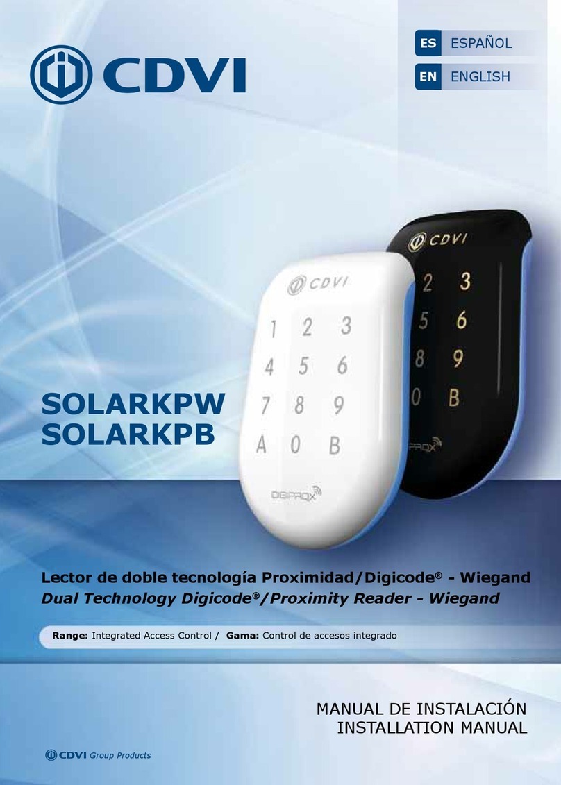
CDVI SOLARKPW User manual

CDVI

CDVI SOLARKPW User manual

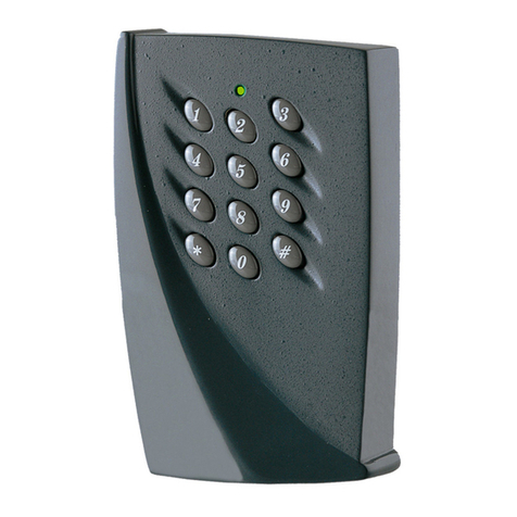
CDVI DGPROX User manual

CDVI

CDVI DGPROX User manual

Popular Security System manuals by other brands

Polon-Alfa 4000 Installation and maintenance manual

Polon-Alfa

Polon-Alfa 4000 Installation and maintenance manual

Nexcom NViS 14162 Series user manual

Nexcom

Nexcom NViS 14162 Series user manual

Eminent EM8670 Quick install

Eminent

Eminent EM8670 Quick install

urmet domus alpha 1060 INSTALLATION AND USE BOOKLET

urmet domus

urmet domus alpha 1060 INSTALLATION AND USE BOOKLET

SmartPool YardGuard YG03 manual

SmartPool

SmartPool YardGuard YG03 manual

DSC PC5964 Mounting instructions

DSC

DSC PC5964 Mounting instructions

Secure USAB-1 operating instructions

Secure

Secure USAB-1 operating instructions

B&B 480 SERIES Operation & maintenance manual

B&B

B&B 480 SERIES Operation & maintenance manual

ADEMCO VISTA-20P Series Installation and setup guide

ADEMCO

ADEMCO VISTA-20P Series Installation and setup guide

Inner Range Concept 2000 user manual

Inner Range

Inner Range Concept 2000 user manual

Johnson Controls PENN Connected PC10 Install and Commissioning Guide

Johnson Controls

Johnson Controls PENN Connected PC10 Install and Commissioning Guide

Aeotec Siren Gen5 quick start guide

Aeotec

Aeotec Siren Gen5 quick start guide

Swann SW-P-MC2 Specifications

Swann

Swann SW-P-MC2 Specifications

Ecolink Siren+Chime user manual

Ecolink

Ecolink Siren+Chime user manual

EDM Solution 6+6 Wireless-AE installation manual

EDM

EDM Solution 6+6 Wireless-AE installation manual

Siren LED GSM operating manual

Siren

Siren LED GSM operating manual

Detection Systems 7090i Installation and programming manual

Detection Systems

Detection Systems 7090i Installation and programming manual

FRIEDLAND MA10 Installation and operating instructions

FRIEDLAND

FRIEDLAND MA10 Installation and operating instructions

manuals.online logo
manuals.online logoBrands
  • About & Mission
  • Contact us
  • Privacy Policy
  • Terms and Conditions

Copyright 2025 Manuals.Online. All Rights Reserved.

EN FR
cdvigroup.com
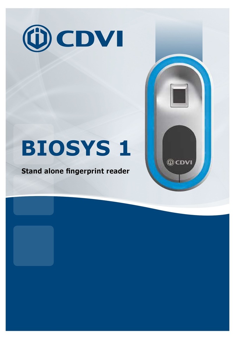
BIOSYS 1
Stand alone ngerprint reader
Lecteur biométrique autonome
The installer’s choice
2
v
1122 141
1 2222
x1 x10
IP 52
-10°C à +50°C
Rappel de câblage
- La distance entre un lecteur et le contrôleur de
porte doit être de 50 m maximum.
- Attention de ne pas passer vos ls à proximité de
câbles «Courant fort» (ex : 230 V AC).
- Câbles préconisés > 3 paires torsadées
(Norme
EIA-485), SYT 3P 24 AWG
- Veillez à respecter le raccordement du l de
blindage PE
Environnement
Le contrôleur doit être impérativement installé en
intérieur.
Le ou les lecteur(s) doivent impérativement être
abrités des intempéries.
Gamme de température de -10°C à +50°C.
Utiliser le joint d’étanchéité fourni.
Recommandation d’installation
Pour limiter les surtensions de selfs, la varistance
doit être montée entre les bornes d’ alimentation
du système de verrouillage.
Alimentations préconisées
(12 VDC)
Deux alimentations sont proposées pour le contrô-
leur
: ADC335 ou BS60.
L’alimentation doit être une source de puissance li-
mitée comme décrite dans la norme EN 600950 - 1
RAPPELS & PRÉCONISATIONS
Wiring Reminder
- The maximum distance between the controller
and the reader head is 50m.
- Beware of mains (240Vac) connections.
- Recommended cables> 3 twisted pairs (EIA-485
standard), 3P SYT 24 AWG.
- Make sure the drain wire PE is connected.
Environment
The door controller must be installed internally.
The reader head must be installed in a sheltered
location from the weather.
Operating temperature range of -10°C to + 50°C.
Use the silicone gasket provided.
Installation Recommendation
To limit back EMF spikes, the varistor must be
installed across the supply terminals of the lock.
Recommended power supplies (12 VDC)
Power supplies must be 12Vdc with a minimum
current provision of 1A. Please ensure you have
taken into account the power requirements of the
lock.
Power supply must be a limited power source as
described in standard EN 600950-1.
This product is a biometric system including a
radioelectric feature. It must be strictly use for
access control.
Ce produit est un équipement biométrique intégrant
une fonctionnalité radioélectrique. Il est exclusive-
ment destiné à une fonction de contrôle d’accès.
Power Supply / Alimentation :12 V DC
Consumption / Consommation : 1 reader / lecteur : 350 mA
2 readers / lecteurs : 480 mA
Frequency Band / Bande de fréquence : 13,553 - 13,567 MHz
Operating Frequency / Fréquence de fonctionnement : 13,56 MHz
Transmitted Power / Puissance émise : 6 dBµA/m
REMINDERS & RECOMMENDATIONS
MASTERBIO USERBIO
EN
Master card
FR
Carte maître
EN
User Card
FR
Carte utilisateur
3
www.cdvigroup.com
IP 52
MOUNTING - MONTAGE
ø8
ø5
35 mm
1.38 po
90°
ø5
35 mm
1.38 po
1
1 2 3 4
5 6 7
4
WIRING - CÂBLAGE
2
M
B
A
1
!
EN
Make sure the drain wire PE
is connected
FR
Veillez à respecter le raccordement
du l de blindage PE
Drain (PE)
Noir / Black
Rouge / Red
Bleu ciel / Light Blue
Bleu foncé / Dark Blue
Bleu ciel / Light Blue
Jaune / Yellow
Pa1
Pa2
Pa3
PE
5
www.cdvigroup.com
WIRING - CÂBLAGE
2
< 50 m / 164 ft
SYT 3P 24AWG
IP52
Pa2
Pa3
RL1
NO C NC
RL2
NO C NC
V
V
12VDC
(-10% / +20%)
12VDC
Alarm
IN
12V
Bus
OUT
12V
Door
Pa1
PE
!
EN
Make sure the drain wire PE
is connected
FR
Veillez à respecter le raccordement
du l de blindage PE
Rouge / Red
Noir / Black
Jaune / Yellow
Bleu foncé / Dark Blue
Bleu ciel / Light Blue
Drain (PE)
6
PARAMETERS - PARAMÉTRAGES
3
26 bits
30 bits
44 bits
WIEGAND
ON
ON
OFF
OFF
OFF
OFF
4 5
ON
8
1 sec.
5 sec.
10 sec.
15 sec.
ON
ON
ON
ON
OFF
OFF
OFF
OFF
OFF
OFF
OFF
OFF
6 7 8
1
BISTABLE MODE
MODE BISTABLE
EN
Bistable mode keeps
the door unlocked until the
BIOSYS1 is not reactivated
by the user.
FR
Le mode bistable maintient
la porte déverrouillée tant que
le BIOSYS 1 n’est pas réactivé
par l’utilisateur.
OR
OU
3
DIP switch
109
NOT USED - NON UTILISÉS
WIEGAND
G
Commun
Ground
H
Clock
D0
Data 0
D1
Data 1
5 V
12 V
ON
OFF
2
1
OFF
MONOSTABLE MODE (lock relay time)
MODE MONOSTABLE (temporisation porte)
EN
Go to chapters
6.3 et 6.4
FR
Aller au chapitres
6.3 et 6.4
7
www.cdvigroup.com
PARAMETERS - PARAMÉTRAGES
J1
J2
J3
J4
J5
P1
ON
OFF
J2
J3
J4
J5
2
ON
ON
OFF
J1
J1 J1
P1
P1 P1
12
INSTALLATION WITH ONE READER HEAD
INSTALLATION AVEC UN LECTEUR BIOSYS EN
Buzzer
FR
Buzzer
EN
Permanently lit
FR
Eclairage permanent
EN
Tamper alarm
FR
Alarme vandalisme
INSTALLATION WITH TWO READER HEADS
INSTALLATION AVEC DEUX LECTEURS
NOT USED
NON UTILISÉ
!
EN
Make sure the drain wire PE
is connected
FR
Veillez à respecter le raccordement
du l de blindage PE
TMBIOSYS
F0106000018
8
X3
1ST COMMISSIONING - 1RE MISE EN SERVICE
4
1/2/3
1START BIOSYS 1
DÉMARRAGE BIOSYS 1
2
ENREGISTREMENT DES EMPREINTES
JUSQU’À 500 UTILISATEURS
X1
X1
X1
!
!
X1
X6
REGISTRATION OF FINGERPRINTS
UP TO 500 USERS
EN
User card
already assigned
FR
Carte utilisateur
déjà affectée
EN
Unknown Master Card
FR
Carte Maître inconnue
EN
Return to chapters 1,2,3
FR
Retour aux chapitres 1,2,3
EN
Let your nger until the BIP and lay it
again on the reader. Do this 6 times.
FR
Laissez votre doigt jusqu’au BIP et
reposez le sur le lecteur. Effectuez cette
manipulation 6 fois.
X1
9
www.cdvigroup.com
USE - UTILISATION
5
X1
X1
1S
!
SPECIFIC CASES - CAS SPÉCIFIQUES
6
1REMOVING A FINGERPRINT
SUPPRESSION D’UNE EMPREINTE
X1 X1
X1
5S / 8S max.
!
EN
Unrecognized ngerprint
FR
Empreinte non reconnue
EN
Unknown user card
FR
Carte utilisateur inconnue
10
4RESET - REMISE À ZÉRO
30S
ON
OFF
OFF
2
41
SPECIFIC CASE - CAS SPÉCIFIQUES SUITE
6
3MASTER CARD CANCELLATION
SUPPRESSION DE LA CARTE MAÎTRE
1S
ON
OFF
OFF
1
X1 X3
2DUPLICATE THE MASTER CARD
DUPLICATION DE LA CARTE MAÎTRE
B
A
B
A
=
DIP switch
DIP switch
EN
Return to chapter 4.1
FR
Retour au chapitre 4.1