Cembre B-TC450 User manual

1
Certified Environmental
Management System Certified Occupational
Health & Safety
Management System
Certified Quality
Management System
OPERATION AND MAINTENANCE MANUAL................................... 5
NOTICE D’UTILISATION ET ENTRETIEN........................................... 10
BEDIENUNGSANLEITUNG................................................................... 15
MANUAL DE USO Y MANTENIMIENTO........................................... 20
MANUALE D’USO E MANUTENZIONE............................................. 25
14 M 109
BATTERY OPERATED HYDRAULIC CUTTING TOOL
COUPE-CABLE HYDRAULIQUE SUR BATTERIE
HYDRAULISCHES AKKU-SCHNEIDWERKZEUG
HERRAMIENTA HIDRÁULICA DE CORTE A BATERíA
UTENSILE OLEODINAMICO DA TAGLIO A BATTERIA
B-TC450 B-TC450A B-TC450E B-TC450T
ENGLISH
FRANÇAIS
DEUTSCH
ESPAÑOL
ITALIANO

2
10
1
1
Low battery
Batterie déchargée
Akku leer
Batería descargada
Batteria scarica
Battery
Batterie
Akku
Batería
Batteria
5
adhesive tape - ruban adhésif
Klebeband - cinta adhesiva
nastro adesivo
15
14
12
3
16
4
5
FIG. / BILD 1 FIG. / BILD 2
FIG. / BILD 3
FIG. / BILD 4
FIG. / BILD 5
17
13
2
2
2

3
1
LED WORKLIGHT / ECLAIRAGE PAR LED / LED ARBEITSLICHT / LUCES LED / ILLUMINAZIONE LED
2
LOCKING PIN / AXE DE BLOCAGE / BLOCKIERUNGSBOLZEN / PASADOR DE SUJECIÓN / PERNO DI BLOCCAGGIO
3
UPPER BLADE / LAME SUPERIEURE / GEGENMESSER / CUCHILLA SUPERIOR / LAMA SUPERIORE
4
LOWER BLADE / LAME INFERIEURE / SCHNEIDMESSER / CUCHILLA INFERIOR / LAMA INFERIORE
5
OPERATING BUTTON / GACHETTE DE COMMANDE / STARTKNOPF / BOTÓN DE ACCIONAMIENTO /
PULSANTE DI AZIONAMENTO
6
PRESSURE RELEASE BUTTON / GACHETTE DE DECOMPRESSION / DRUCKABLASSKNOPF / BOTÓN DE DESBLO-
QUEO PRESIÓN / PULSANTE DI RILASCIO
7
BATTERY / BATTERIE / AKKU / BATERÍA / BATTERIA
8
BATTERY CAPACITY INDICATOR / INDICATEUR DE CHARGE / AKKUANZEIGE / INDICADOR DE CARGA BATERIA /
INDICATORI AUTONOMIA BATTERIA
9
BATTERYCHECKBUTTON/BOUTONPOURCONTROLDE LABATTERIE /TASTEFÜR AKKUÜBERPRÜFUNG/BOTÓN
DE CONTROL BATERÍA / PULSANTE DI VERIFICA BATTERIA
10
BATTERYRELEASE/DEBLOCAGEBATTERIE/AKKUENTRIEGELUNG /DESBLOQUEOBATERÍA/SBLOCCOBATTERIA
11
RING FOR SHOULDER STRAP / ANNEAU POUR BANDOULIERE / TRAGERIEMENRING / ANILLO PARA CORREA /
ANELLO AGGANCIO TRACOLLA
FIG. / BILD 6
1
11
5
6
7
2
1
10
9
8
4
3

4
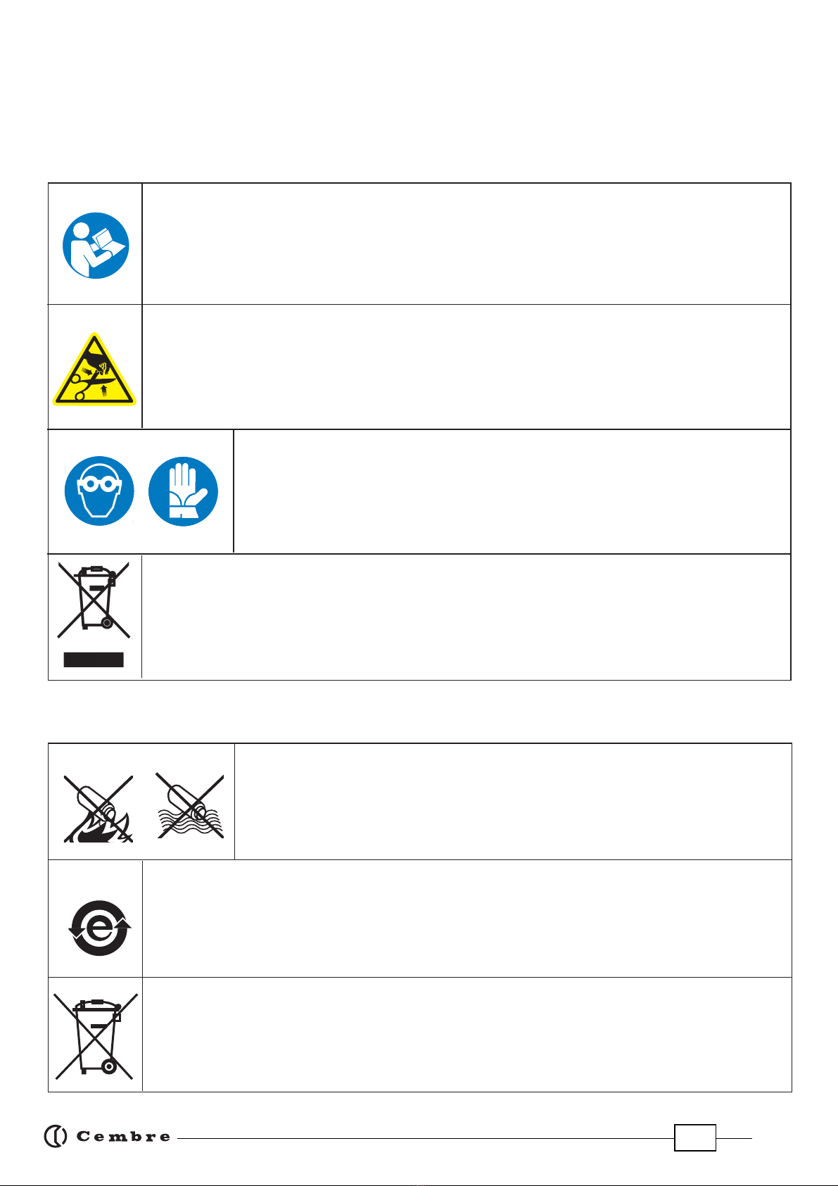
– Before using the tool, carefully read the instructions in this manual.
– Avant d'utiliser cet outil, lire attentivement les instructions de cette notice.
– Vor Inbetriebnahme unbedingt die Bedienungsanleitung durchlesen.
– Antes de utilizar la herramienta, leer atentamente las instrucciones en este manual.
– Prima di utilizzare l'utensile, leggere attentamente le istruzioni riportate in questo manuale.
– Keep hands clear of cutting blades.
– Au cours du coupage, tenir les mains éloignées des lames.
– Während des Schneidens die Hände von den Messern fernhalten.
– Durante el corte, tener las manos alejadas de las cuchillas.
– Durante il taglio, tenere le mani lontane dalle lame.
– Always wear safety glasses and gloves when operating this tool.
– Porter toujours les lunettes de protection et les gants de travail.
– Immer mit Schutzbrille und Handschuhen bedienen.
– Trabajar siempre con las gafas y guantes de seguridad.
– Operare sempre con occhiali di protezione e guanti da lavoro.
WARNING SYMBOLS - SYMBOLES D'AVERTISSEMENT - WARNSYMBOLE -
SÍMBOLOS DE ADVERTENCIA - SIMBOLI DI AVVERTENZA
– Never throw batteries into re or water.
– Jamais jeter les batteries dans le feu ou dans l'eau.
– Werfen Sie Akkus nicht in das Feuer oder Wasser.
– Nunca tire las baterías al fuego o al agua
– Mai gettare le batterie nel fuoco o in acqua.
– Always recycle the batteries.
– Recycler toujours les batteries.
– Verbrauchte Akkus stets dem Recycling zuführen.
– Reutilizar siempre las baterías.
– Riciclare sempre le batterie.
– Do not discard batteries into domestic refuse or waste disposal.
– Ne pas jeter de batteries dans une poubelle ou autre lieu non prévu à cet eet.
– Verbrauchte Akkus nicht in den Hausmüll werfen.
– No tirar las baterías al cubo de basura o lugar parecido.
– Non buttate le batterie fuori uso nei cestini della spazzatura o luoghi simili.
– User information (Directives 2002/95/EC and 2002/96/EC), see page 9.
– Information pour les utilisateurs (Directives 2002/95/CE et 2002/96/CE) voir page 14.
– Information für den Benutzer (Richtlinien 2002/95/EG und 2002/96/EG) siehe Seite 19.
– Informe para los usuarios (Directivas 2002/95/CE y 2002/96/CE) vease página 24.
– Informazione agli utenti (Direttive 2002/95/CE e 2002/96/CE) vedere pagina 29.
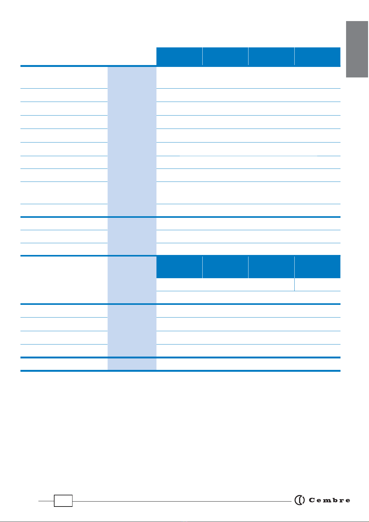
Battery -Batterie - Akku - Batería - Batteria
Tool - Outil - Werkzeug - Herramienta - Utensile
TG 0960

5
1. GENERAL CHARACTERISTICS
B-TC450
B-TC450E B-TC450T B-TC450A
Application range suitable for cutting Copper, Aluminium, ACSR and Steel
conductors, ropes and rods (Ref. to pag. 30)
Max. cutting diameter mm (inches) 45 (1-25/32”)
Operating pressure
bar (psi) 700 (10,000)
Dimensions mm (inches) 407 x 401 x 88 (16 x 15.8 x 3.5)
Weight with battery kg (lbs) 6,7 (14.7)
Motor V DC 18
Operating temperature °C (°F) -15 to +50 (+5 to +122)
Recommended oil AGIP ARNICA 32 or equivalents
Operating speed twin speed operation and automatic switching from a rapid
advancing speed of the ram to a slower, more powerful speed
Safety maximum pressure valve
Rechargeable battery V / Ah / Wh 18 / 4.0 / 72
Type CB1840L (Li-Ion)
Weight kg (lbs) 0,66 (1.45)
Battery charger
ASC30-36
Input
type EU
27044000
UK
27045000
AUS/NZ
27047000
USA/CAN
27046000
V / Hz 220 - 240 / 50 - 60 115 / 60
W85
Acoustic noise
(1)
L
pA
dB (A)
73
L
pCPeak
dB (C) 94.5
L
WA
dB (A) 79
Vibration
(2)
m/s
2
0.575 max.
ENGLISH
(1) Directive 2006/42/EC, annexe 1, point 1.7.4.2 letter u)
LpA
= weighted continuous acoustic pressure level equivalent.
LpCPeak
= maximum value of the weighted acoustic displacement pressure at the work place.
LWA
= acoustic power level emitted by the machine.
(2) (Directive 2006/42/EC, annexe 1, point 2.2.1.1)
Weighted root mean square in frequency of the acceleration the upper limbs are exposed to for each biodynamic
reference axis. Tests carried out in compliance with the indications contained in UNI ENV 25349 and UNI EN 28662
part 1st Standards, and under operating conditions much more severe than those normally found.

6
ENGLISH
WARNING
Do not use the tool for purposes other than those intended by Cembre.
The operator should concentrate on the work being performed and be careful to maintain a
balanced working position.
Work in a clean, uncluttered area. Keep persons away from immediate work area.
Inspect the blades before each use. Do not use damaged blades.
Damaged blades can break and cause injury or damage to the tool.
Before each use, verify the integrity of the tool; replace any worn, possibly damaged or missing
parts with original Cembre spares.
Wear eye protection. Metal chips can y from blades when cutting.
Pay attention when cutting short, free pieces of steel rod or rope as they may y o dangerously,
causing injury to the operator or persons nearby.
Do not cut live cables or conductors.
The tool is unsuitable for continuous use and should be allowed to cool down following uninter-
rupted, successive cutting operations; for instance, having exhausted a fully charged battery in
one session, delay battery replacement for a few minutes.
Protectthetoolfromrainandmoisture.Waterwilldamagethetoolandbattery. Electro-hydraulic
tools should not be operated in pouring rain.
The part reference includes the following:
Hydraulic cutting tool
Li-Ion rechargeable battery (2 pcs)
Battery charger (model depends on the tool version)
Shoulder strap
Carrying case
ENGLISH
2. INSTRUCTIONS FOR USE
The tool can be easily carried using either the handle or the shoulder strap attached to ring (11)
(Ref. to Fig. 6).
Th
e
H
L
B
S
C

7
Before starting any work, check the battery charge (Ref. to § 2.7) and recharge if necessary,
following the instructions in the battery charger user manual.
To replace the battery, remove it by pressing the release button (10) (Ref. to Fig. 1), then insert
the new battery, sliding it into the guides until it locks.
2.1) Head rotation
For ease of operation, the tool head can rotate through 180°, allowing the operator to work in the
most comfortable position (Ref. to Fig. 2 and 3).
Do not attempt to rotate the head when the hydraulic circuit is pressurised.
2.2) Setting
Insert the conductor between the blades, up to the desired cutting point (Ref. to Fig. 2).
To cut short pieces of steel or ACSR ropes, it is suggested to tie or wrap rope with
adhesive or duct tape around the area to be cut and at its end (Ref. to Fig. 2), so to limit
the projection of steel fragments which could damage or hurt the operator.
For a running conductor, remove the locking pin (2) and open the tool head.
Fully retract the lower blade (4) before attempting to open the tool head (Ref. to § 2.6).
With the conductor on the lower blade (4), close the tool head and fully insert the locking pin
(2) (Ref. to Fig. 3).
Before commencing the cutting operation ensure that the pin (2) is fully secured: partial
closure may damage the tool head.
2.3) Blade advancement
Operate the push-button (5) (Ref. to Fig. 2) to activate the motor-pump, the ram will gradually
move forward until the lower blade (4) touches the conductor.
To halt the advancement, release the push-button (06) and the motor will cut out.
Make sure the blade is exactly positioned on the desired cutting point otherwise re-open the
blade following instructions as per § 2.6 and reposition it.
2.4) Cutting
Firmly hold the tool and operate the push-button (5) to gradually move the lower blade (4) to
cut through the conductor.
When the cut is performed, release the push-button (5), otherwise after the maximum pressu-
re relief valve has activated and the motor will stop automatically.
ENGLISH

8
ENGLISH
2.5) LED Worklights
Whilst the tool is in operation, the work areais illuminated by two high luminosity LEDWorklights
that switch o automatically at the end of the cycle.
2.6) Blade retraction
By operating the pressure release button (6), the ram will retract and open the blades.
2.7) Battery status
The battery is equipped with LED indicators that indicate the
remaining battery life at any time by pressing the adjacent
button (9):
4 LEDs illuminated: fully charged
2 LEDs illuminated: 50 % capacity
1 LED flashing : minimum charge, replace the battery.
Tool LEDs (1) illuminated combined with an alarm audible when the operating button (5)
is pressed (Ref. to Fig. 4), indicate that the battery voltage has dropped below a minimum
safety threshold; under these conditions the tool will not start, and it is necessary to recharge or
replace the battery.
The approximate time to fully recharge a battery is about 80 minutes.
After each working cycle, and after the extraction of the battery from the tool, an integrated
battery cut-o device will operate after 70 s approx. Then the LED nearest to button (9) will
ash 5 times each 14 s approx. The battery will be reactivated when it is reintroduced into the tool
and the operating button is pressed.
2.8) Using the battery charger
Carefully follow the instructions in the battery charger user manual.
3. MAINTENANCE
The tool is robust, completely sealed, and requires very little daily maintenance. Compliance with
the following points, should help to maintain its optimum performance:
3.1) Thorough cleaning
Dust, sand and dirt are a danger for any hydraulic device. Every day, after use, the tool must be
wiped with a clean cloth taking care to remove any residue, especially close to pivots and move-
able parts.
Do not use hydrocarbons to clean the rubber parts.
Regularly lubricate the moving parts and pivot pins of the head with a few drops of oil.
3.2) Storage case
When not in use, the tool should be stored and transported in the plastic case, to prevent damage.
The case, type VAL P37, is suitable for storing the tool and accessories.
VAL P37: Size 500x480x128 mm (19.7x18.9x5.0 inches). Weight 3,1 kg (6.8 lbs).
9
ENGLISH

9
4. BLADE REPLACEMENT (Ref. to Fig. 5)
When changing blades, the battery must rst be removed from the tool.
After extended use, the blades may break or loose their cutting edge.
Replace the blades as follows:
Lower blade
– Remove locking pin (2), and open the tool head completely.
– Operate the tool to advance the lower blade (4) and remove the battery.
– Eject two split pins (12) from the ram (13) to release the blade (4).
– Remove the broken blade from the ram, insert the new blade and t with two split pins.
Before closing the tool head, push the release button (6) and fully retract the lower blade,
otherwise the tool head assembly may hit and damage, the lower blade.
Upper blade
– With the lower blade (14) fully retracted, the tool head closed and the locking pin (2) fully
secured, hold the head by the blade spacer (15) in a bench vice with screws (16) facing upwords.
– With an 8 mm allen key, unscrew 4 screws (16), remove the two holding plates (17) and the up-
per blade (3).
– Insert the new blade, noting the position of the cutting edge bevel.
– Fit the 2 holding plates (17) and secure with 4 screws (16).
5. RETURN TO Cembre FOR OVERHAUL
In the case of a breakdown, contact your local Agent who will advise you on the problem and give
you the necessary instructions on how to dispatch the tool to our nearest service Centre; if possible,
attach a copy of the Cembre Test Certicate supplied with the tool or, if no other references are
available, indicate the approximate purchase date and the tool serial number.
Following information applies in member states of the European Union:
USER INFORMATION in accordance with“Directives 2002/95/EC and 2002/96/EC.
The ‘Not in the bin’ symbol above when shown on equipment or packaging means that the
equipment must, at the end of its life, be disposed of separately from other waste.
The separate waste collection of such equipment is organised and managed by the manufacturer.
Users wishing to dispose of such equipment must contact the manufacturer and follow the prescri-
bed guidelines for its separate collection. Appropriate waste separation, collection, environmentally
compatible treatment and disposal is intended to reduce harmful environmental eects and pro-
mote the reuse and recycling of materials contained in the equipment. Unlawful disposal of such
equipment will be subject to the application of administrative sanctions provided by current legi-
slation.
ENGLISH

10
1.CARACTERISTIQUES GENERALES
B-TC450
B-TC450E B-TC450T B-TC450A
Domaine d'application conçu pour couper des câbles métalliques en cuivre,
aluminium, almelec, aluminium-acier, acier et ronds massif
(voir page 30
)
Diamètre maxi. de coupe mm (inches) 45 (1-25/32”)
Pression de travail bar (psi) 700 (10,000)
Dimensions mm (inches) 407 x 401 x 88 (16 x 15.8 x 3.5)
Poids avec batterie kg (lbs) 6,7 (14.7)
Moteur V DC 18
Température de fonction-
nement:
°C (°F) -15 à +50 (+5 à +122)
Huile recommandée: AGIP ARNICA 32 ou équivalents.
Avance rapide:
l’outil passe automatiquement de la vitesse rapide
à la vitesse lente de coupage.
Sécurité valve de surpression.
Batterie rechargeable V / Ah / Wh 18 / 4.0 / 72
Type CB1840L (LI-Ion)
Poids kg (lbs) 0.66
Chargeur de batterie
ASC30-36
Alimentation
type EU
27044000
UK
27045000
AUS/NZ
27047000
USA/CAN
27046000
V / Hz 220 - 240 / 50 - 60 115 / 60
W85
Bruit aérien sonore
(1)
L
pA
dB (A) 73
L
pCPeak
dB (C) 94.5
L
WA
dB (A) 79
Vibrations
(2)
m/s
2
0.575 maxi.
FRANÇAIS
(1) (Directive 2006/42/CE, annexe 1, point 1.7.4.2, lettre u)
LpA
= niveau de pression sonore continue équivalente pondérée A sur le poste de travail.
LpCPeak
=niveau de pression sonore instantanée pondérée C sur le poste de travail.
LWA
= niveau de puissance acoustique dégagée par la machine.
(2) (Directive 2006/42/CE, annexe 1, point 2.2.1.1)
Valeur quadratique moyenne pondérée en fréquence de l'accélération à laquelle sont exposés les membres supérieurs
pour chaque axe biodynamique de référence. Relevés réalisés suivant les indications des Normes UNI ENV 25349 et
UNI EN 28662 partie 1a, dans des conditions de service largement représentatives des conditions d'emploi normales.

11
FRANÇAIS
AVERTISSEMENT
Ne pas utiliser cet outil à des ns diérentes que celles prévues par le constructeur.
Restezbien attentiftout au longdu travail, nesoyezpasdistrait,ne perdezpas l’équilibre pendant
l'utilisation.
Travailler dans un espace propre et ordonné. Eloigner les personnes de la zone de travail.
Contrôler les lames avant chaque utilisation. Ne pas utiliser l’outil avec une lame endommagée.
Les lames endommagées peuvent abîmer l’outil.
Remplacer les pièces usagées et éventuellement endommagées ou manquantes avec des pièces
de rechange originales Cembre.
Toujours porter une visière de protection pendant les opérations de coupe, car de petits éclats de
câbles peuvent être propulsés.
Faire attention au moment de couper de morceaux courts des câbles ou ronds massif en acier,
car ils pourraient être projetés dangereusement et blesser l’opérateur ou une personne proche.
Ne pas couper de câble sous tension électrique.
L’outil n’est pas conçu pour une utilisation en continu; après avoir eectué une quantité de coupe
consécutifs à partir d’une batterie complètement chargée, au moment du remplacement de la
batterie, nous suggérons d’observer une période d’arrêt pour permettre le refroidissement de
l’outil.
Protéger l’outil de la pluie et de l’humidité. L’eau pourrait endommager l’outil et la batterie, les
outils hydro-électriques ne devraient pas être utilisés sous la pluie.
L' ensemble comprend:
Coupe-câble hydraulique
Batterie rechargeable Li-Ion (2 pcs)
Chargeur de batterie (diérent en fonction de la
version de l'outil).
Bandoulière.
Coret de rangement.
2.INSTRUCTIONS D'UTILISATION
L’outil peut être transporté facilement grâce à sa poignée et à la bandoulière accrochée par l'anneau
(11) (Réf a Fig. 2).
L'

12
Avant de commencer toute opération, contrôler l’état de charge de la batterie (voir § 2.7) et,
si nécessaire, la recharger en suivant les instructions contenues dans le manuel d’utilisation
du chargeur de batteries.
Pour remplacer la batterie, la retirer en appuyant sur le mécanisme de déblocage (10) (Réf. a Fig. 1)
puis introduire la nouvelle batterie en la faisant coulisser sur les guides jusqu’au blocage complet.
2.1) Rotation de la tête
La tête de l'outil pivote de 180° par rapport au corps, permettant à l'utilisateur de travailler dans
la meilleure position.
Ne pas forcer la rotation de la tête, lorsque le circuit hydraulique est sous pression.
2.2) Préparation
Positionner le câble entre les lames de façon à ce qu'elles soient en correspondance avec la
position de coupe souhaitée (Réf. a Fig. 2).
Pour couper de courts morceaux de câbles en acier ou en alu-acier, il est suggéré de lier
ou bien d'enrouler l’extrémité et le point de coup avec du ruban adhésif (Réf. a Fig. 2);
ça limitera la projection d’éclats en acier qui pourrait causer des dommages ou lésions à
l’opérateur.
Si le câble est passant, il sera alors nécessaire d’ouvrir la tête en tirant l'axe de blocage (2) per-
mettant la rotation et l'ouverture de la tête.
L’ouverture de la tête ne devra être eectuée qu'avec la lame inférieure (4) complètement
baissée.
Poser la lame inférieure (4) contre le câble à couper, refermer la tête en la verrouillant à l’aide
de l'axe (2) (Réf. a Fig. 3).
Avant d’eectuer l’opération de coupe, s’assurer que l'axe (2) soit parfaitement inséré.
2.3) Avance des lames
Appuyer sur la gâchette de commande (5) (Réf. a Fig. 2) pour mettre en marche le groupe
moteur-pompe; la lame inférieure commence l'approche du câble.
La gâchette de commande relâchée, le moteur et l'avance de la lame inférieure cessent im-
médiatement.
S'assurer que les lames sont bien positionées sur la zone à couper, sinon desserer les lames
en suivant les instructions du § 2.6 et repositioner le câble.
2.4) Coupe
Tenez l'outil fermement et appuyer sur la gâchette de commande (5) pour mettre en marche le
moteur; la lame inférieure avance progressivement jusqu’à ce que le câble soit coupé com-
plètement.
Relâchez la gâchette de commande (5) lorsque la coupe est eectuée.
Si l'on maintient le moteur actionné, l’outil s’arrêtera automatiquement avec l'intervention de la
valve de surpression.
FRANÇAIS

13
FRANÇAIS
2.5) Led
Lors de l’actionnement de l’outil, la zone de travail est éclairée au moyen de deux LED haute
luminosité qui s’éteignent automatiquement à la n du cycle.
2.6) Réouverture des lames
En appuyant à fond sur la gâchette de déblocage (6), on provoque le retour du piston et par
conséquent l'ouverture la lame inférieure.
2.7) Autonomie de la batterie
La batterie est équipée d’indicateurs à LED qui permettent de
contrôler,àtoutmoment,sonautonomierésiduelleenappuyant
sur le bouton (9):
4 led allumées: autonomie maximale
2 led allumées: autonomie à 50 %
1 led clignotante: autonomie minimale, remplacer la batterie.
L'éclairage des deux Led (1) associé à l’avertisseur sonore lorsqu’on appuie sur le bouton de
déclenchement (5) (Réf. a Fig. 4) indique que la batterie est déchargée et que sa tension est
descendue au-dessous du seuil minimal de sécurité; dans cette situation, l’outil ne démarre pas, il
est donc nécessaire de recharger ou de remplacer la batterie.
À titre indicatif, le délai de recharge complète de la batterie correspond à environ 80 min.
A la n de chaque cycle de travail comme à l’extraction de la batterie de l’outil, un dispositif
électronique arrête automatiquement la batterie après environ 70 s.
Pour conrmer cette opération, la led la plus proche du bouton (9) clignotera 5 fois en 14 s
(approximativement). La batterie est réactivée dès sa réintroduction dans l’outil, ou en appuyant
sur le bouton d’actionnement.
2.8) Utilisation du chargeur de batterie
Suivre attentivement les instructions indiquées sur le manuel.
3.ENTRETIEN
L'outilestrobuste,complètementscelléetnenécessiteaucunepréoccupationouattentionparticulière.
Lesrecommandationsquisuiventsontnéanmoinssouhaitablespourassurerunelongévitéoptimum:
3.1) Nettoyage élémentaire
Veiller à protéger l'outil de la poussière, du sable et de la boue qui sont un danger à tout système
hydraulique. Chaque jour après utilisation, l'outil doit être nettoyé à l'aide d'un chion propre,
tout particulièrement aux endroits de pièces mobiles.
Ne jamais utiliser d’hydrocarbures pour le nettoyage des parties en caoutchouc.
Lubrier régulièrement les parties mobiles et les axes de la tête avec quelques gouttes d’huile.
3.2) Rangement
Au repos, pour protéger l'outil des coups accidentels et de la poussière, il convient de le ranger
dans le coret.
Ce coret (type VAL P37), adapté pour contenir l'outil et ses accessoires a comme dimensions:
500x480x128 mm (19.7x18.9x5.0 inches) et un poids de 3,1 kg (6.8 lbs).
9

14
4. CHANGEMENT DES LAMES (Voir Fig. 5)
Le changement des lames doit être effectué avec l’outil dépourvu de batterie.
Il peut arriver qu' une utilisation prolongée ou non appropriée cause la perte d’aûtage des lames
ou leur endommagement. Le changement des lames est cependant très simple.
Lame inférieure
– Retirer l’axe de blocage (2) et ouvrir le groupe supérieur, jusqu’à la butée.
– Actionner l'outil pour faire avancer la lame inférieure (4) et enlever la batterie.
– Expulser les goupilles élastiques (12) sur le piston (13) de façon à libérer la lame (4).
– Enlever la vieille lame et introduire la lame neuve sur le piston et la bloquer avec les 2 goupilles
élastiques.
Avant de refermer la tête appuyer sur la gâchette de déblocage (6) de façon à ce que la lame
inférieure redescende complètement pour éviter qu’elle soit heurtée et endommagée.
Lame supérieure
– La lame inférieure baissée, vérier que le groupe supérieur soit bien fermé et verrouillé par l’axe
de blocage (2), positionner la tête dans un étau en serrant le guide (15)de façon à ce que les vis
(16) soient accessibles par le haut.
– A l’aide d’une clé allen de 8 mm, retirer les 4 vis (16), et démonter les deux plaquettes (17); la lame
supérieure (3) sera ainsi libérée.
– Positionner la nouvelle lame de façon à ce que le dégorgement du tranchant soit orienté vers le
haut.
– Replacer les deux plaquettes (17), et serrer les 4 vis (16).
5. ENVOI EN REVISION A Cembre
En cas de dysfonctionnement de l'appareil, merci de vous adresser à notre Agent Régional qui
vous conseillera et le cas échéant vous donnera les instructions nécessaires pour envoyer l'outil
à notre Centre de Service le plus proche. Dans ce cas, joindre une copie du Certicat d'Essai livré
par Cembre avec l'outil ou, à défaut d'autres éléments de référence, indiquer la date d'achat ap-
proximative et numéro de série.
Les informations suivantes sont destinées aux pays membres del'Union Européenne:
INFORMATION POUR LES UTILISATEURS aux termes des“Directives 2002/95/CE et 2002/96/CE.
Le symbole“poubelle barrée”apposé sur l’appareil ou sur son emballage indique que le produit, à la
n de sa vie utile, doit être recueilli séparément des autres déchets.
La collecte sélective du présent appareil en n de vie est organisée et gérée par le producteur. L’uti-
lisateur qui voudra se défaire du présent appareil devra par conséquent contacter le producteur et
suivre le système que celui-ci a adopté pour consentir la collecte séparée de l’appareil en n de vie.
La collecte sélective adéquate pour l’envoi successif de l’appareil destiné au recyclage, au traitement
et à l’élimination compatible avec l’environnement contribue à éviter les eets négatifs possibles
sur l’environnement et sur la santé et favorise la réutilisation ou le recyclage des matériaux dont
l’appareil est composé. L’élimination abusive du produit par le détenteur comporte l’application des
sanctions administratives prévues par les lois en vigueur.
FRANÇAIS

15
1. ALLGEMEINE EIGENSCHAFTEN
B-TC450
B-TC450E B-TC450T B-TC450A
Anwendungsbereich GeeignetzumSchneidenvonKupfer-undAluminiumkabeln,
Aldreyseilen, Stahlseilen und Stahlstangen (siehe Seite 30).
Max. Schneiddurchmesser mm (inches) 45 (1-25/32”)
Arbeitsdruck bar (psi) 700 (10,000)
Abmessungen mm (inches) 407 x 401 x 88 (16 x 15.8 x 3.5)
Gewicht inkl. Akku kg (lbs) 6,7 (14.7)
Motor V DC 18
Betriebstemperatur: °C (°F) -15 bis +50 (+5 bis +122)
Empfohlenes Öl: AGIP ARNICA 32 oder ähnliches
Kolbenvorschub:
Das Werkzeug ist mit einer Doppelkolbenhydraulik
ausgerüstet. Beim Beginn des Arbeitsvorganges
wird auf den langsameren Arbeitshub umgeschaltet.
Sicherheit: Überdruckventil
Wiederauadbarer Akku V / Ah / Wh 18 / 4.0 / 72
Typ CB1840L (Li-Ionen)
Gewicht kg (lbs) 0,66 (1.45)
Akkuladegerät
ASC30-36
Eingangspannung
Typ EU
27044000
UK
27045000
AUS/NZ
27047000
USA/CAN
27046000
V / Hz 220 - 240 / 50 - 60 115 / 60
W85
Lärmschutzbestimmung
(1)
L
pA
dB (A)
73
L
pCPeak
dB (C) 94.5
L
WA
dB (A) 79
Vibrationen
(2)
m/s
2
0.575 max.
DEUTSCH
(1) Richtlinie 2006/42/EG, Anhang 1, Nummer 1.7.4.2, Buchstabe u)
LpA
= konstanter Lärmpegel entsprechend Gewichtung A am Arbeitsplatz
LpCPeak
= höchster Lärmpegel entsprechend Gewichtung C am Arbeitsplatz
LWA
= Lärmbelastung des Geräts
(2) Richtlinie 2006/42/EG, Anhang 1, Nummer 2.2.1.1)
Der Wert bezieht sich auf Messungen, entsprechend der Normen UNI ENV 25349 und UNI EN 28662 Teil 1 unter re-
präsentativen Bedingungen, bei dem der durchschnittliche Messwert an den oberen Teilen den Wert nicht überschritt.

16
HINWEISE
Verwenden Sie das Akkuwerkzeug ausschließlich für den vom Hersteller vorgesehenen Anwen-
dungszweck.
Arbeiten Sie konzentriert und lassen Sie sich während des Einsatzes nicht ablenken und nehmen
zur Arbeit eine sichere und standfeste Arbeitsposition ein!
Den Arbeitsbereich immer sauber halten und es sollten sich keine weitere Menschen im Arbeits-
bereich aufhalten.
Überprüfen Sie die Schneidmesser vor jedem Gebrauch. Verwenden Sie nie ein Werkzeug mit
beschädigtenSchneidmessern.DefekteSchneidmesserkönntendasWerkzeugstarkbeschädigen.
Vor jeder Benutzung die Unversehrtheit des Kopfes überprüfen. Verschlissene, beschädigte oder
fehlende Teile durch Originalersatzteile von Cembre ersetzen.
Tragen Sie immer eine Schutzbrille, da sich beim Schneiden Metallsplitter lösen können.
AchtenSiebeimSchneidenvonStangenundStahlseilendarauf,dasssichkeinePersoneninder
Nähe aufhalten. Es können sich kleine Teile lösen und dann zu Verletzungen führen.
Es dürfen keine unter Spannung stehenden Teile geschnitten werden.
Die Akkuwerkzeuge sind nicht für einen Dauereinsatz geeignet. Wenn ein voll geladener Akku
durch hintereinander ausgeführte Schnitte getauscht werden muss, empfehlen wir vor dem
Akkuwechsel das Werkzeug eine angemessene Zeit abkühlen zu lassen.
Das Werkzeug vor Regen und Feuchtigkeit schützen. Wasser könnte das Werkzeug und den Akku
beschädigen. Elektrohydraulische Werkzeuge sollten nicht im Regen oder unter ießendem
Wasser eingesetzt werden.
Zum Lieferumfang unter dieser Bezeichnung ge-
hören folgende Teile:
Hydraulisches Akku-Schneidwerkzeug
2 Stück wiederaufladbare Li-Ion Akkus
Ladegerät(entsprechendderLänderkonguration)
Trageriemen
Koer
2. BEDIENUNGSHINWEISE
Das Werkzeug kann bequem am Gri oder mit dem Trageriemen, der am Ring (Bild 6 T.11) befestigt
ist, transportiert werden.
DEUTSCH

17
Überprüfen Sie vor jedem Arbeitsvorgang den Ladezustand der Akkus (siehe Pkt. 2.7) und
laden Sie bei Bedarf die Akkus entsprechend den Anweisungen in der Bedienungsanleitung
des Akkuladegerätes auf.
Drücken Sie für den Akkuaustausch auf die Entriegelung (10) (siehe Bild 1) und führen Sie den
neuen Akku bis zum Einratsen ein.
2.1) Drehbewegung des Kopfes
DasWerkzeug ist miteinemKopf ausgerüstet,der um180°drehbaristund somiteinkomfortables
Arbeiten ermöglicht (siehe Bild 2 und 3).
Der Kopf darf keinesfalls in eine andere Position gedreht werden, während das Werkzeug
unter Druck steht.
2.2) Vorbereitung
Das zu schneidende Seil am gewünschten Schnittpunkt zwischen den Schneidmessern positio-
nieren (siehe Bild 2).
Wenn kurze Abschnitte von Stahl- bzw. Aluminium-Stahl Seilen geschnitten werden,
ist es ratsam das Ende mit Isolierband zu fixieren (siehe Bild 2).
Damit werden mögliche Verletzungen des Anwenders verhindert.
Bei durchgehendem Seil wird das Gegenmesser durch Öffnen der Blockierungsbolzen (2)
zurückgeklappt.
Das Önen des Gegenmessers darf nur mit ganz zurückgefahrenem Schneidmesser (4)
erfolgen (siehe Pkt. 2.6).
Das Schneidmesser (4) um das zu schneidende Seil legen. Den Kopf schliessen und den Bolzen
(2) einrasten lassen (siehe Bild 3).
Vor dem Schneiden hat man sich zu vergewissern, daß der Bolzen (2) einwandfrei
eingerastet ist.
2.3) Schneidvorgang
Durch Drücken des Startknopfes (5) (siehe Bild 2) wird der Pumpenmotor gestartet, wobei sich
das Schneidmesser dem Seil annähert.
Das Zusammenfahren der Schneidmesser kann durch Loslassen des Startknopfes (5) gestoppt
werden.
Auf diese Weise kann kontrolliert werden, dass sich die Schneidmesser genau auf dem
zuschneidenden Punktbefinden. Istdies nichtder Fall,sind die Schneidmesser zuöffnen
(siehe § 2.6) und erneut zu positionieren.
2.4) Schneiden
Halten Sie das Werkzeug fest und durch Drücken des Startknopfes (5) beginnt der Motor zu
arbeiten, der Kolben lässt das Schneidmesser allmählich nach vorn fahren, bis das Seil vollständig
geschnitten worden ist.
Wenn der Schnitt ausgeführt ist, den Startknopf (5) loslassen. Wenn der Startknopf weiter
betätigt wird, arbeitet das Werkzeug weiter bis zur Abschaltung durch das Überdruckventil.
DEUTSCH

18
2.5) LED
Während der Betätigung des Werkzeugs wird der Schneidbereich von zwei LED-Anzeigen mit
hoher Helligkeit ausgeleuchtet, die sich am Zyklusende automatisch abschalten.
2.6) Zurückfahren des Schneidmessers
Drücken Sie kräftig des Druckablassknopf (6) , der sich unterhalb des Startknopfes (5) bendet.
Dadurch fährt der Kolben zurück und das Schneidmesser gibt das Kabel frei.
2.7) Akkuladung
Die Akku ist mit LED-Anzeigen ausgestattet, die jederzeit über
die verbleibende Akkulaufzeit Auskunft gibt, indem man auf
die Taste (9) drückt:
4 LED eingeschaltet: Maximale Ladung
2 LED eingeschaltet: Ladung zu 50 %
1 LED blinkend: Minimale Ladung, Akku austauschen bzw. auaden.
Wenn der Akku nicht mehr ausreichende Ladung hat, wird beim Betätigen des Startknopfes
(5) über die LED Leuchten (1) zusammen mit einem akustischen Signal (siehe Bild4) das
Erreichendes Mindestsicherheitsniveau signalisiert. UnterdiesenBedingungen kanndasWerkzeug
nicht in Betrieb genommen werden. Laden Sie den Akku auf oder tauschen Sie ihn aus.
Ein vollständiger Ladevorgang eines leeren Akkus dauert etwa 80 Minuten.
Nach jedem Arbeitszyklus und wie auch nach der Entfernung des Akkus schaltet es durch
die eingebaute Elektronik nach ca. 70s automatisch ab.
Als Bestätigung des Vorganges wird die LED bei der Taste (9) 5-mal hintereinander innerhalb von
ca. 14s blinken. Durch das Einführen des Akkus in das Werkzeug wird der Akku wieder aktiviert oder
durch die Betätigung des Startknopfes.
2.8) Verwendung des Ladegerätes
Die in der Bedienungsanleitung gegebenen Hinweise sind zu beachten.
3. WARTUNG
Das Werkzeug ist robust und benötigt keine spezielle Pege.
Zur Erhaltung der Garantieansprüche beachten Sie folgende Hinweise:
3.1) Pege
Dieses hydraulische Werkzeug sollte vor starker Verschmutzung geschützt werden, da dies für
ein hydraulisches System gefährlich ist. Jeden Tag nach der Arbeit sollte dasWerkzeug mit einem
Tuch von Schmutz und Staub gereinigt werden, besonders die beweglichen Teile. Verwenden
Sie keine Kohlenwasserstoe (z.B. Teilereiniger, Bremsenreiniger) zum Reinigen der Gummiteile.
Alle beweglichen Teile und Bolzen regelmäßig mit einem Tropfen Öl einölen.
3.2) Lagerung
Wenn das Werkzeug nicht benötigt wird, sollte es in dem Kunststokoer gelagert werden und ist
somit gegen Beschädigungen wie Stoß und Staub geschützt.
Der Kunststokoer Typ VAL P37 hat folgende Abmessungen: 500x480x128 mm (19.7x18.9x5.0
inches)undeinGewichtvon3,1 kg (6.8 lbs.). EristgeeignetzumLagernvomWerkzeugundZubehör.
9
DEUTSCH

19
4. SCHNEIDMESSER WECHSELN (siehe Bild 5)
Der Wechsel der Schneidmesser muss immer mit ausgebautem Akku erfolgen.
Nach längerem Gebrauch oder nach Anwendungsfehlern kann es zu Abnutzungen (beschädigt,
unscharf) an den Messern kommen. Bei einem Wechsel sollten Sie wie folgt vorgehen:
Schneidmesser
– Den Blockierungsbolzen (2) entfernen und den oberen Teil bis zum Anschlag önen.
– Den Motor betätigen und das Schneidmesser (4) nach vorne fahren und entfernen Sie den Akku.
– Die beiden Federstifte (12) vom Kolben (13) entfernen und somit kann das Schneidmesser (4)
entnommen werden.
– Anschließend mit der Federstifte das neue Schneidmesser wieder montieren.
Bevor das Gegenmesser wieder geschlossen wird, drücken Sie kräftig den Druckablassknopf
(6), so wird sichergestellt dass das Schneidmesser komplett zurück gefahren ist und es nicht
zu einer Beschädigung der Schneidmesser kommt.
Gegenmesser
– Bei vollständig zurückgefahrenem Schneidmesser (4) und geschlossenem Kopf auf dem Zwis-
chenstück (15) im Schraubstock spannen und dabei auf die Schrauben (16) achten.
Mit einem 8 mm Inbusschlüssel die vier Schrauben (16) lösen und die zwei Platten (17) entfernen.
Das Gegenmesser (3) ist jetzt zugänglich und kann entfernt werden.
– Das neue Schneidmesser einlegen (dabei darauf achten das die Schneidseite nach oben
gedreht ist).
– Die Platten (17) und die 4 Schrauben (16) wieder montieren.
5. EINSCHICKEN AN Cembre ZUR ÜBERPRÜFUNG
Sollten am Gerät Fehler auftauchen, wenden Sie sich bitte an unsere Gebietsvertretung, welche
Sie gerne beraten und Ihnen alle nötigen Informationen zum Einschicken des Gerätes an unseren
Hauptsitz geben wird. Wenn vorhanden, legen Sie dem Gerät bitte das von Cembre mitgelieferte
Überprüfungszertikat bei. In Ermangelung dieser Informationen geben Sie bitte an, wann Sie das
Gerät erworben haben.
Die folgenden Hinweise gelten für Mitglieder der Europäischen Union:
I
NFORMATION FÜR DEN BENUTZER gemäß der“Richtlinien 2002/95/EG und 2002/96/EG.
Das durchkreuzte Zeichen auf dem Mülleimer, welches auf dem Gerät oder seiner Verpackung ange-
bracht ist, zeigt an, dass das Produkt am Ende seiner Lebenszeit getrennt von den anderen Abfällen
entsorgt werden muss. Die getrennte Abfallsammlung des vorliegenden zu entsorgenden Geräts
wird vom Hersteller organisiert und verwaltet. Der Besitzer, der sich des Geräts entledigen will, muss
sich daher mit dem Hersteller in Verbindung setzen und das von ihm angenommene System für die
getrennte Sammlung des zu entsorgenden Geräts befolgen.
Eine angemessene getrennte Sammlung, damit das Gerät für das Recycling, die Behandlung und
die umweltfreundliche Entsorgung vorbereitet werden kann, trägt dazu bei, mögliche negative
Auswirkungen auf die Umwelt und auf den Gesundheitszustand zu vermeiden und begünstigt die
Wiederverwertung und das Recycling der Materialien des Geräts. Bei widerrechtlicher Entsorgung
des Produkts durch den Benutzer werden die vom Gesetz vorgesehen Verwaltungssanktionen ange-
wandt.
DEUTSCH

20
1. CARACTERíSTICAS GENERALES
B-TC450
B-TC450E B-TC450T B-TC450A
Campo de aplicación: idónea para cortar cables y varillas de cobre, aldrey,
aluminio, aluminio-acero y varillas de acero (Ref. a pag. 30)
Diámetro max. de corte
mm (inches) 45 (1-25/32”)
Presión de trabajo bar (psi) 700 (10,000)
Dimensiones mm (inches) 407 x 401 x 88 (16 x 15.8 x 3.5)
Peso con batería kg (lbs) 6,7 (14.7)
Motor V DC 18
Temp. de funcionamiento °C (°F) -15 a +50 (+5 a +122)
Aceite recomendado AGIP ARNICA 32 ó equivalentes.
Velocidad de avance son dos: una rápida y otra más lenta de trabajo.
El paso de una a otra velocidad es automático.
Seguridad válvula de sobrepresión.
Batería recargable V / Ah / Wh 18 / 4.0 / 72
Tipo CB1840L (Li-Ion)
Peso kg (lbs) 0,66 (1.45)
Cargador de batería
ASC30-36
Alimentación
tipo EU
27044000
UK
27045000
AUS/NZ
27047000
USA/CAN
27046000
V / Hz 220 - 240 / 50 - 60 115 / 60
W85
Ruido aéreo
(1)
L
pA
dB (A) 73
L
pCPeak
dB (C) 94.5
L
WA
dB (A) 79
Vibraciones
(2)
m/s20.575 max.
ESPAÑOL
(1) Directiva Europea 2006/42/CE, anexo 1, punto 1.7.4.2, letra u)
LpA
= nivel de presión acústica contínua equivalente ponderado A en el puesto de trabajo.
LpCPeak
= nivel máximo de la presión acústica instantánea ponderada C en el puesto de trabajo.
LWA
= nivel de potencia acústica emitida por la máquina.
(2) Directiva Europea 2006/42/CE, anexo 1, punto 2.2.1.1)
Valor cuadrático medio ponderado en frecuencia, de la aceleración a la que están expuestos los miembros supe-
riores para cada eje biodinámico de referencia. Medidas realizadas según las indicaciones de las Normas UNI ENV
25349 y UNI EN 28662 parte 1a, en condiciones de utilización ampliamente representativas respecto a las que se
encuentran normalmente.
This manual suits for next models
3
Table of contents
Languages:
Other Cembre Cutter manuals

Cembre
Cembre B35M-TFC User manual

Cembre
Cembre B-TC500YA User manual

Cembre
Cembre B-TC250 User manual

Cembre
Cembre HT-TC026 User manual

Cembre
Cembre HT-TFC User manual

Cembre
Cembre HT-TC055 Installation guide

Cembre
Cembre B-TC250YA User manual

Cembre
Cembre B35 User manual

Cembre
Cembre HT-TC026Y User manual

Cembre
Cembre HT-TC051 User manual

Cembre
Cembre HT-TC051Y User manual

Cembre
Cembre TC085 User manual

Cembre
Cembre HT-TC026 User manual

Cembre
Cembre B-TC550NA User manual

Cembre
Cembre TC050 User manual

Cembre
Cembre TC050Y User manual

Cembre
Cembre B-TC04 User manual

Cembre
Cembre TC 120 User manual

Cembre
Cembre B-TC04 User manual

Cembre
Cembre B-TC320ND User manual