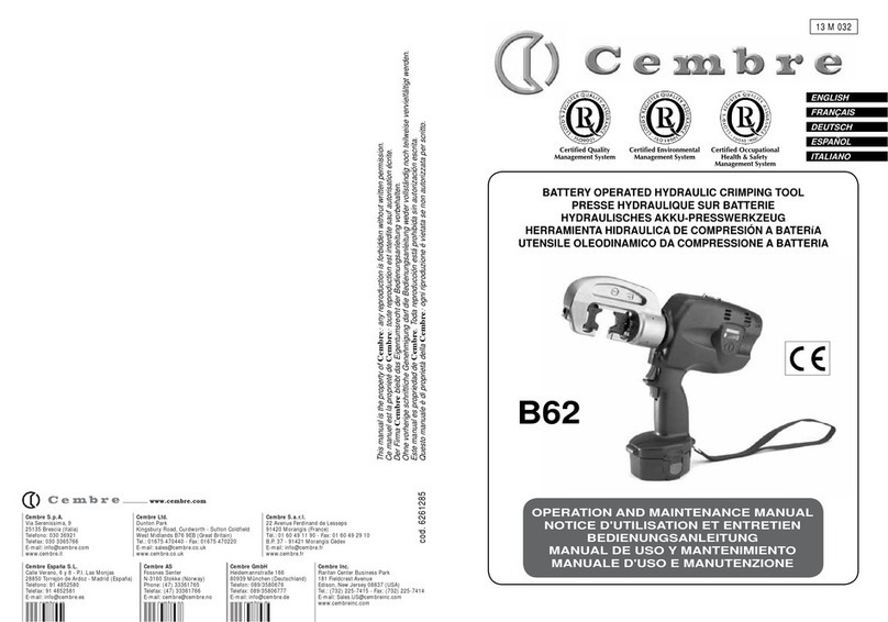
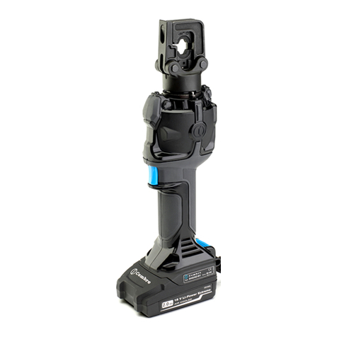
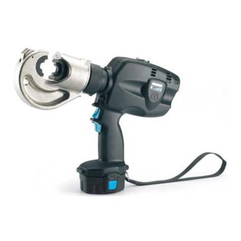
Cembre TW-18B User manual

1
TW-18B TW-18BA TW-18BE
22M265 - 6261537
250 Nm
BATTERY CALIBRATED TORQUE WRENCHBATTERY CALIBRATED TORQUE WRENCH
BOULONNEUSE DYNAMOMÉTRIQUE SUR BATTERIE A COUPLE CONTRÔLÉBOULONNEUSE DYNAMOMÉTRIQUE SUR BATTERIE A COUPLE CONTRÔLÉ
AKKU-SCHRAUMASCHINE MIT KONTROLLIRETEM DREHMOMENTAKKU-SCHRAUMASCHINE MIT KONTROLLIRETEM DREHMOMENT
ATORNILLADOR DINAMOMÉTRICO DE BATERÍA DE PAR CONTROLADOATORNILLADOR DINAMOMÉTRICO DE BATERÍA DE PAR CONTROLADO
AVVITATORE DINAMOMETRICO A BATTERIA A COPPIA CONTROLLATAAVVITATORE DINAMOMETRICO A BATTERIA A COPPIA CONTROLLATA
OPERATION AND MAINTENANCE MANUAL..............................5
(Translation of the original instruction)
NOTICE D’UTILISATION ET ENTRETIEN........................................25
(Traduction des instructions originales)
BEDIENUNGSANLEITUNG...........................................................45
(Übersetzung der Originalanleitung)
MANUAL DE USO Y MANTENIMIENTO......................................65
(Traducción de las instrucciones originales)
MANUALE D’USO E MANUTENZIONE........................................85
(Istruzioni originali)
ENGENGLISHLISH
FRANÇAISFRANÇAIS
DEUTSCHDEUTSCH
ESPAÑOLESPAÑOL
ITALIANOITALIANO

2
2
3
19
FIG. /BILD 1
9
11
12
A
B
C
4
18
5
10
15
16
17
6
1
1314
8
D
7
E

3
a
b
1
2
CLIP-NR...
CLIP-NR...
Socket wrench Douille Steckschlüssel
Llave de vaso Chiave a bussola
Push here
Presser ici
Hier drücken
Empujar aqui
Spingere qui
FIG. / BILD 3
FIG. / BILD 2
5
2
2
C
M
0
0
1
2
0
2
2
-
S
1
K
4
0
5
0
1
FIG. / BILD 5
USB-C
7
1011
E
9
814
12
TG1262
dim. 65x47 mm
materiale PET laminato PC
Via Serenissima, 9 - 25135 Brescia - Italy
36 V
ALIMENTAZIONE MOTORE
MOTOR SUPPLY
250 Nm
20
MAX. COPPIA DI SERRAGGIO
MAX. TIGHTENING TORQUE
TW-18B
TYPE / TIPO
YEAR / ANNO
Made in Italy
imported in the UK by CEMBRE Ltd, Curdworth, B76 9EB, UK
BATTERY CALIBRATED TORQUE WRENCH
AVVITATORE DINAMOMETRICO A BATTERIA
FIG. / BILD 4
13

4
Click
2
P
G
FIG. / BILD 6
1
3
FIG. / BILD 7
FIG. / BILD 8
21
15
19
19 8
W SFSF ON
FASTENER
200-250Nm
SEQUENCE
000000
JOB
000000
01/01/2022
08:00
W SFSF ON
FASTENER
200-250Nm
SEQUENCE
000000
JOB
000000
01/01/2022
08:00
W SFSF ON
FASTENER
200-250Nm
SEQUENCE
000000
JOB
000000
OK
01/01/2022
08:00
W SFSF ON
FASTENER
200-250Nm
SEQUENCE
000000
JOB
000000
01/01/2022
08:00
UNSCREW
01/01/2022
08:00
01/01/2022
08:00
ERROR
TW-18B
RUN
RUN

5
GENERAL POWER TOOLS
SAFETY WARNINGS
WARNING. Read all safety warnings, instructions, illustrations and specifications provided
with this power tool.
Failure to follow all instructions listed below may result in electric shock, fire and/
or serious injury.
Save all warnings and instructions for future reference.
The term“power tool” in the warnings refers
to your mains-operated (corded) power tool or battery-operated (cordless) power tool.
1) Work area safety
• Keep work area clean and well lit.
Cluttered or dark areas invite accidents.
• Do not operate power tools in explosive atmospheres, such as in the presence of flammable
liquids, gases or dust.
Power tools create sparks which may ignite the dust or fumes.
• Keep children and bystanders away while operating a power tool.
Distractions can cause you to
lose control.
2) Personal safety
• Stay alert, watch what you are doing and use common sense when operating a power tool. Do
not use a power tool while you are tired or under the influence of drugs, alcohol or medication.
A moment of inattention while operating power tools may result in serious personal injury.
• Use personal protective equipment. Always wear eye protection.
Protective equipment such as a
dust mask, non-skid safety shoes,hard hat or hearing protection used for appropriate conditions will reduce
personal injuries.
• Do not overreach. Keep proper footing and balance at all times.
This enables better control of the
power tool in unexpected situations.
• Dress properly. Do not wear loose clothing or jewelry. Keep your hair and clothing away from
moving parts.
Loose clothes, jewelry or long hair can be caught in moving parts.
• Do not let familiarity gained from frequent use of tools allow you to become complacent and
ignore tool safety principles.
A careless action can cause severe injury within a fraction of a second
.
3) Power tool use and care
• Do not force the power tool. Use the correct power tool for your application.
The correct power
tool will do the job better and safer at the rate for which it was designed.
• Do not use the power tool if the switch does not turn it on and off.
Any power tool that cannot be
controlled with the switch is dangerous and must be repaired.
• Disconnect the plug from the power source and/or remove the battery pack, if detachable,
from the power tool before making any adjustments, changing accessories, or storing power
tools.
Such preventive safety measures reduce the risk of starting the power tool accidentally.
EN

6
• Store idle power tools out of the reach of children and do not allow persons unfamiliar with the
power tool or these instructions to operate the power tool.
Power tools are dangerous in the hands
of untrained users.
• Maintain power tools and accessories. Check for misalignment or binding of moving parts,
breakage of parts and any other condition that may affect the power tool’s operation. If damaged,
have the power tool repaired before use.
Many accidents are caused by poorly maintained power tools.
• Use the power tool, accessories etc. in accordance with these instructions, taking into account
the working conditions and the work to be performed.
Use of the power tool for operations different
from those intended could result in a hazardous situation.
• Keep handles and grasping surfaces dry, clean and free from oil and grease.
Slippery handles and
grasping surfaces do not allow for safe handling and control of the tool in unexpected situations.
4) Battery tool use and care
• Recharge only with the charger specified by the manufacturer.
A charger that is suitable for one type
of battery pack may create a risk of fire when used with another battery pack.
• Use power tools only with specifically designated battery packs.
Use of any other battery packs may
create a risk of injury and fire.
• When battery pack is not in use, keep it away from other metal objects, like paper clips, coin,
keys, nails, screws or other small metal objects, that can make a connection from one terminal
to another.
Shorting the battery terminals together may cause burn or a fire.
• Under abusive condition,liquid may be ejected from battery; avoid contact.If contact accidentally
occurs, flush with water. If liquid contacts eyes, additionally seek medical help.
Liquid ejected
from the battery may cause irritation or burns.
• Do not use a battery pack or tool that is damaged or modified.
Damaged or modified batteries may
exhibit unpredictable behaviour resulting in fire, explosion or risk of injury.
• Do not expose a battery pack or tool to fire or excessive temperature.
Exposure to fire or temperature
above 130° C may cause explosion.
• Follow all charging instruction and do not charge the battery pack or tool outside temperature
range specified in the instruction.
Charging improperly or at temperatures outside the specified
range may damage the battery and increase the risk of fire.
5) Service
• Have your power tool serviced by a qualified repair person using only identical replacement
parts.
This will ensure that the safety of the power tool is maintained.
• Never service damaged battery packs.
Service of the battery packs Should only be performed by the
manufacturer of authorized service providers.
EN
7
IMPORTANT:
The tool is provided with two labels that act as seals on the start buttons.They must only be
removed when the operator, having switched on the tool, presses one of the two buttons with
the resulting rotation of the driveshaft; the “first start-up”will begin a countdown of the days
remaining until the next calibration (See § 9.1.3)
SYMBOLOGY:
Explanation of symbols in the label on the machine (Fig. 2):
Read instructions in this manual before using the tool.
KEEPTHESE INSTRUCTIONS: this manual contains important tool safety and operating
instructions for correct use.
During use, keep hands and feet away from the pinch point between the reaction arm and
rail contact surface.
Always wear safety gloves.
Always wear safety footwear.
Mark of compliance with. European safety regulations.
Mark of compliance with UK safety regulations.
Do not dispose of this equipment with ordinary household waste!This equipment must be
disposed of in compliance with the Waste Electrical and Electronic Equipment Directive
2012/19/EU for proper processing and recycling (Ref. to page 24).
Examples of battery compartment label (Fig. 3):
22CM001:
tool serial number
2022 - S1K40501
:
year of manufacture - firmware version
Explanation of symbols used in this manual:
Failure to comply with this instruction may lead to serious physical injury.
Failure to comply with this instruction may cause damage to the equipment or lead to
operating error.
EN

8
1. GENERAL CHARACTERISTICS
298 (11.7)
440 (17.3)
440 (17.3)
675 (26.6)
440 (17.3)
FIG. 9 Dimensions in mm (inch)
Torque wrench type TW-18B TW-18BE TW-18BA
Max. torque developed Nm 250 +0 /-50
Brushless motor V 36
Degree of protection (motor-battery group)
IP
IP44M (EN 60529)
Weight (without battery and reaction arm) kg 11.5
Weight (with battery and reaction arm) kg 14
Dimensions (Ref. to Fig. 9) mm 675 x 440 x h298
Temperature of use °C (°F) -20 a +50 (-4 to +122)
Acoustic noise (1) dB LpA = 71.3 (A) uncertainty K = 0.9
LWA = 83.8 (A) uncertainty K = 0.9
Vibrations (2) m/s2< 2,5
Li-Ion rechargeable battery type CB3680L
Voltage / Current / Energy V / Ah / Wh 36 / 8.0 / 288
Weight kg 1.9
Battery charger
type
ASC145
-EU
ASC145
-UK
ASC145
-USA/CA
Power plug type
EU -
type
C UK -
type
G US -
type
A
Input V / Hz (W) 220 - 240 / 50 - 60 (190)
115 / 60
(190)
Output
V / A 10.8 - 36 / 8 max.
Weight kg 0.6
(1) Tests carried out in compliance with the EN 62841-2-2 Standard indications:
LpA: A-weighted continuous acoustic pressure level in the work place.
LWA: Acoustic power level emitted by the machine.
(2) The total value of the vibrations (triaxial vector sum) was measured according to EN 62841-2-2 Standard indications and can be
used for tool comparison; the total vibration value can also be used in a preliminary exposure assessment.
WARNING: vibration in the actual use of the electrical tool may be different from the declared value, depending on the method
of use; in order to protect the operator, safety measures must be identified according to the conditions of use, in order to protect
the operator, based on the estimated exposure under actual conditions of use.
EN

9
A) CB3680L rechargeable battery (2 pcs) 36V 8,0 Ah (LiHDTechnology) Li-Ion, equipped with LED
indicators of the remaining battery life at any time by pressing the button.
B) ASC145 fast charger (1 pc) differs depending on geographic region.
Use to charge the battery supplied, minimal current consumption in stand-by mode, management of the
charging process by means of a processor. AIR COOLED function for quicker cooling of the battery in case
of overheating.
C) CLIP-NR (3 pcs) retaining circlip for fixing most common sockets with grooved diameter from 47 to 57
mm (1.85 to 2.25 in.).
D) CLIP-NR57 (1 pc) retaining circlip for fixing sockets with grooved diameter from 57 to 67 mm
(2.25 to 2.64 in.).
E) USB flash drive with dual USB-A / USB-C connectors for saving and transferring data to a PC.
3. SUPPLIED ACCESSORIES (Ref. to Fig. 1)
2. DESCRIPTION (Ref. to Fig. 1)
1.1) Compliance of use
– The device is a battery powered torque wrench, mainly suitable for fastening threaded components (bolts,
screws, nuts) with controlled tightening torque. It is intended primarily for track maintenance operations
in the railway sector. It can be used both, as a portable tool and in wheeled mode in combination with the
specific support trolley. Any other use, or use deemed to be outside of the specification of the device shall
be regarded as improper use. In these instances the manufacturer/supplier shall not be liable for any
damage resulting from improper use and the user agrees to bear all risk.
– The device is manufactured in accordance with current technological standards and recognized safety
rules. However, danger to life and limb of the user or third parties/or damage to the device and other
tangible assets can arise during use.
– The device may only be used for its intended purpose and if in perfect working order, and it must be used
with appropriate consideration given to the safety and danger warning messages stated in the operating
manual.
– Usage of the device for its intended purpose also incorporates compliance with the operating manual,
including the manufacturer‘s maintenance recommendations and specifications.
EN
1 Moveable attachment pin for support trolley
2 Information/warning label
3 LED lighting x2
4 Shock absorber x4
5 1”square drive
6 Motor unit
7 Push button ON/OFF (EMERGENCY)
8 Motor start button (clockwise)
9 Safety lock
10 Menu selector knob
11 Colour display
12 Power supply/USB flash drive side cover
13 Safety lock
14 Motor start button (counterclockwise)
15 Rainproof battery compartment cover
16 Reaction arm
17 Reaction arm locking button
18 36V d.c. Brushless Motor
19 Handgrip x2

10
W SFSF ON
FASTENER
200-250Nm
SEQUENCE
000000
JOB
000000
01/01/2022
08:00
W SFSF ON
FASTENER
200-250Nm
SEQUENCE
000000
JOB
000000
01/01/2022
08:00
W SFSF ON
FASTENER
200-250Nm
SEQUENCE
000000
JOB
000000
OK
01/01/2022
08:00
W SFSF ON
FASTENER
200-250Nm
SEQUENCE
000000
JOB
000000
01/01/2022
08:00
UNSCREW
01/01/2022
08:00
01/01/2022
08:00
ERROR
TW-18B
RUN
RUN
EMERGENCY ON/OFF button (7)
Located on the motor in a position clearly visible to the operator, it can be activated quickly in case of
emergency.
Press the button to switch on the tool: the display will turn on, showing the main information.
Press again to switch off: the display will turn off.
AUTO-SHUTDOWN: in order to optimise the battery life, a timer will disconnect the power
supply if the tool is inactive for a period of 5 minutes; To reactivate the tool, press the
button (7) again.
Start button (8and14)
Press to start the motor with clockwise or counterclockwise rotation.
Safety lock (9 and 13)
Press to unlock the mechanism that prevents the tool from being activated accidentally.
The start button must be pressed at the same time as the safety lock.
Menu selector (10)
Only works when the display is turned on:
Can be turned either clockwise or counterclockwise
in order to select the various menu screens.
Press to access the chosen screen then turn to
select the desired value highlighted in light blue.
Press to confirm the selection or the chosen value.
LED colour display (11)
The high-brightness colour display turns on when
the torque wrench is switched on and turns off au-
tomatically after a period of inactivity. It shows:
- The main operational parameters of the
tool.
- Information on the condition of the tool.
- Type of work to be carried out.
- Any operational or procedural alerts (See § 8).
4. CONTROLS / INDICATORS (See Fig. 1 and 4)
5 min.
tightening torque Job No.
type of fastening data logging ON or OFF
sequence of progress along the track
direction date /time battery charge level
of rotation
bar
progress
fastening
CLICK
1sec.
CLICK
10
EN

11
LED lights (3)
The 2 LEDs make it possible to light the working area and are useful for poorly lit conditions.
They turn on automatically when the torque wrench is used and turn off approximately 10 seconds after the
motor has stopped.
The navigation menu is shown on the display (11).
The selector knob (10) allows the user to browse the
menu, select a parameter and confirm a selection:
Turn to select a screen and to move within the
screen, the selected parameter will be highlighted
in light blue.
Press to enter the screen or to confirm a selection.
5. NAVIGATION MENU
5
BAT1 BAT2
NR-25B
FW S1K54601
Loremipsum
21AW090
Lorem ipsum
MOTOR
0h 00m
0h 00m
BATT. NTC
FAULT
DRIVER
5
!
MOTOR A
!FW
5
5
5
5
BAT1 BAT2
5
BAT1 BAT2
5
BAT1 BAT2
1
BAT1 BAT2
BAT1 BAT2
BAT1 BAT2
BAT1 BAT2
BAT1 BAT2
CLICK
10
Initial screen
This shows for several seconds when the tool is switched on.
Main screen (example)
summarises the tool’s main configuration parameters:
date/time and battery charge level
W: Fastening configuration
SFSF: progress along the track (for work certification only)
ON: data recording enabled (for work certification only)
The main screen is shown each time the display turns on
Fastening type
allows the operator to select the configuration of the component to be
fastened, choosing between: W, N, K and KS.The system automatically
sets the corresponding tightening torque:
W, K, KS=200-250 Nm N=150-200 Nm.
N.B: it is compulsory to set this parameter before proceeding with any
fastening.
11
W SFSF ON
FASTENER
200-250Nm
SEQUENCE
000000
JOB
000000
01/01/2022
08:00
W SFSF ON
FASTENER
200-250Nm
SEQUENCE
000000
JOB
000000
01/01/2022
08:00
W SFSF ON
FASTENER
200-250Nm
SEQUENCE
000000
JOB
000000
OK
01/01/2022
08:00
W SFSF ON
FASTENER
200-250Nm
SEQUENCE
000000
JOB
000000
01/01/2022
08:00
UNSCREW
01/01/2022
08:00
01/01/2022
08:00
ERROR
TW-18B
RUN
RUN
5.1) Menu screens
W SFSF ON
FASTENER
200-250Nm
SEQUENCE
000000
JOB
000000
01/01/2022
08:00
W SFSF ON
FASTENER
200-250Nm
SEQUENCE
000000
JOB
000000
01/01/2022
08:00
W SFSF ON
FASTENER
200-250Nm
SEQUENCE
000000
JOB
000000
OK
01/01/2022
08:00
W SFSF ON
FASTENER
200-250Nm
SEQUENCE
000000
JOB
000000
01/01/2022
08:00
UNSCREW
01/01/2022
08:00
01/01/2022
08:00
ERROR
TW-18B
RUN
RUN
W
N
KS
K
01/01/2022
08:00
FASTENER
N
W
KS
K
01/01/2022
08:00
FASTENER
N
W
KS
K
01/01/2022
08:00
FASTENER
N
W
KS
K
01/01/2022
08:00
FASTENER
01/01/2022
08:00
SEQUENCE
SSSS
FFFF
SSFF
FREE
SFSF
START
01/01/2022
08:00
SSSS
FFFF
SSFF
FREE
SFSF
SEQUENCE
START
01/01/2022
08:00
SSSS
FFFF
SSFF
FREE
SFSF
SEQUENCE
01/01/2022
08:00
SSSS
FFFF
SSFF
FREE
SFSF
SEQUENCE
TOT:
PAR:
000517
000031
01/01/2022
08:00
CYCLES
Long push for reset
01/01/2022
08:00
CYCLES
TOT:
PAR:
000517
000000
PUSH L
PUSH
PUSH
TURNTURN
TURN
TURN
TURN
TURN PUSH
PUSH
EN

12
Operator progress (for work certification only)
Determine how the operator will advance along the track during the work by choosing
between:
SSSS = fastening of attachments on the internal side only
FFFF = fastening of attachments on the external side only
SSFF= fastening of 2 consecutive attachments on the internal side and 2 on the
external side
SFSF = fastening of one attachment on the internal side and one on the external side
FREE = progress freely
Recording of work or JOBs (for work certification only)
Select:
ON to enable the data recording before carrying out the work.
OFF to stop recording after the work has been completed.
If recording is not necessary, keep OFF.
Work cycles
TOT: total no. of cycles completed since the first start-up of the tool.
PAR: partial no. of cycles
Press the selector (10) for at least 3 seconds to reset the
partial counter: 000000.
Time
total and partial tool usage time expressed in hours (h) and minutes (m)
Press the selector (10) for at least 3 seconds to reset the partial counter: 0h
00m.
SSFF
START START
SSSS SFSF
START
FREE
STARTSTART
FFFF
W
N
KS
K
01/01/2022
08:00
FASTENER
N
W
KS
K
01/01/2022
08:00
FASTENER
N
W
KS
K
01/01/2022
08:00
FASTENER
N
W
KS
K
01/01/2022
08:00
FASTENER
01/01/2022
08:00
SEQUENCE
SSSS
FFFF
SSFF
FREE
SFSF
START
01/01/2022
08:00
SSSS
FFFF
SSFF
FREE
SFSF
SEQUENCE
START
01/01/2022
08:00
SSSS
FFFF
SSFF
FREE
SFSF
SEQUENCE
01/01/2022
08:00
SSSS
FFFF
SSFF
FREE
SFSF
SEQUENCE
TOT:
PAR:
000517
000031
01/01/2022
08:00
CYCLES
Long push for reset
01/01/2022
08:00
CYCLES
TOT:
PAR:
000517
000000
PUSH L
PUSH
PUSH
TURNTURN
TURN
TURN
TURN
TURN PUSH
PUSH
TOT:
PAR:
002h24m
000h56m
CLOCK
Long push for reset
CLOCK
TOT:
PAR:
002h24m
000h00m
JOB
01/01/2022
08:00
OFF
ON
JOB
01/01/2022
08:00
OFF
ON
01/01/2022
08:00
DISPLAY
01/01/2022
08:00
DISPLAY
Turn the button to set the brightness.
Push to confirm.
TURN TURN
PUSH L
PUSH
PUSH
01/01/2022
08:00
DISPLAY
01/01/2022
08:00
DISPLAY
PUSH PUSH
TURN
The validity of the calibration
has expired.
Contact an authorized CEMBRE service
center to carry out ordinary maintenance.
JOB FUNCTION NOT AVAILABLE
W
N
KS
K
01/01/2022
08:00
FASTENER
N
W
KS
K
01/01/2022
08:00
FASTENER
N
W
KS
K
01/01/2022
08:00
FASTENER
N
W
KS
K
01/01/2022
08:00
FASTENER
01/01/2022
08:00
SEQUENCE
SSSS
FFFF
SSFF
FREE
SFSF
START
01/01/2022
08:00
SSSS
FFFF
SSFF
FREE
SFSF
SEQUENCE
START
01/01/2022
08:00
SSSS
FFFF
SSFF
FREE
SFSF
SEQUENCE
01/01/2022
08:00
SSSS
FFFF
SSFF
FREE
SFSF
SEQUENCE
TOT:
PAR:
000517
000031
01/01/2022
08:00
CYCLES
Long push for reset
01/01/2022
08:00
CYCLES
TOT:
PAR:
000517
000000
PUSH L
PUSH
PUSH
TURNTURN
TURN
TURN
TURN
TURN PUSH
PUSH
TOT:
PAR:
002h24m
000h56m
CLOCK
Long push for reset
CLOCK
TOT:
PAR:
002h24m
000h00m
JOB
01/01/2022
08:00
OFF
ON
JOB
01/01/2022
08:00
OFF
ON
01/01/2022
08:00
DISPLAY
01/01/2022
08:00
DISPLAY
Turn the button to set the brightness.
Push to confirm.
TURN TURN
PUSH L
PUSH
PUSH
01/01/2022
08:00
DISPLAY
01/01/2022
08:00
DISPLAY
PUSH PUSH
TURN
The validity of the calibration
has expired.
Contact an authorized CEMBRE service
center to carry out ordinary maintenance.
JOB FUNCTION NOT AVAILABLE
EN

13
Display brightness
is variable so that it can be adapted to suit the
ambient conditions of use.
Sun: maximum brightness 100 %
Moon: variable brightness from 10 to 80 %
Turn the selector (10) and press to confirm
the selection.
Download data to USB drive
Check that the USB drive is inserted into the USB-C port located within
the control panel.
Press the selector (10) for at least 3 seconds
Date and time
To ensure that work certification is correct, always check that the date and
time are accurate. If adjustment is needed:
Turn the selector (10) and press once to confirm the selection.
The tool is equipped with a back-up CR1620 battery.In the event the battery
is completely empty, it will not be possible to set and retain the date and time
on the display, please contact CEMBRE for further information.
Info
torque wrench model
serial number
firmware version and circuit board hardware
Exp: calibration certificate expiry date
TW-18B
22AA258
FW-S1J40601
HW-123
Exp: 19/06/2022
01/01/2022
08:00
INFO
TURN
01/01/2022
08:00
DATA DOWNLOAD
Long push to
data download
The operation may take a few minutes
01/01/2022
08:00
DATA DOWNLOAD
Download in progress
Do not remove the battery
Run phase is not allowed during download
Long push to stop data download
01/01/2022
08:00
DATA DOWNLOAD
Download completed
LONG PUSH
01/01/2022
08:00
DATA DOWNLOAD
Download interrupted
Data was not saved
LONG PUSH
2022/01/01
14:00
DATE
01/01/2022
08:00
TW-18B
22AA258
FW-S1J40601
HW-123
Exp: 19/06/2022
01/01/2022
08:00
INFO
TURN
01/01/2022
08:00
DATA DOWNLOAD
Long push to
data download
The operation may take a few minutes
01/01/2022
08:00
DATA DOWNLOAD
Download in progress
Do not remove the battery
Run phase is not allowed during download
Long push to stop data download
01/01/2022
08:00
DATA DOWNLOAD
Download completed
LONG PUSH
01/01/2022
08:00
DATA DOWNLOAD
Download interrupted
Data was not saved
LONG PUSH
TOT:
PAR:
002h24m
000h56m
CLOCK
Long push for reset
CLOCK
TOT:
PAR:
002h24m
000h00m
JOB
01/01/2022
08:00
OFF
ON
JOB
01/01/2022
08:00
OFF
ON
01/01/2022
08:00
DISPLAY
01/01/2022
08:00
DISPLAY
Turn the button to set the brightness.
Push to confirm.
TURN TURN
PUSH L
PUSH
PUSH
01/01/2022
08:00
DISPLAY
01/01/2022
08:00
DISPLAY
PUSH PUSH
TURN
The validity of the calibration
has expired.
Contact an authorized CEMBRE service
center to carry out ordinary maintenance.
JOB FUNCTION NOT AVAILABLE
TOT:
PAR:
002h24m
000h56m
CLOCK
Long push for reset
CLOCK
TOT:
PAR:
002h24m
000h00m
JOB
01/01/2022
08:00
OFF
ON
JOB
01/01/2022
08:00
OFF
ON
01/01/2022
08:00
DISPLAY
01/01/2022
08:00
DISPLAY
Turn the button to set the brightness.
Push to confirm.
TURN TURN
PUSH L
PUSH
PUSH
01/01/2022
08:00
DISPLAY
01/01/2022
08:00
DISPLAY
PUSH PUSH
TURN
The validity of the calibration
has expired.
Contact an authorized CEMBRE service
center to carry out ordinary maintenance.
JOB FUNCTION NOT AVAILABLE
EN

14
6. RECHARGEABLE BATTERIES
6.1) Safety instructions for batteries:
Protect battery from water and moisture!
Do not expose batteries to naked flames!
A slightly acidic, flammable fluid may leak from defective Li-ion batteries!
If battery fluid leaks out and comes into contact with your skin, rinse immediately
with plenty of water. If battery fluid leaks out and comes into contact with your
eyes, wash them with clean water and seek medical attention immediately!
At the end of their life, always recycle batteries.
Never discard batteries with domestic waste, they must be sent to appropriate
collection centres for disposal.
If the machine is defective, remove the batteries.
Do not use faulty or deformed batteries!
Do not open batteries!
Do not touch or short circuit battery contacts!
Optimal battery storage temperature is between 10 and 30 °C (50 and 86 °F).
Remove the battery from the machine to transport the machine.
For transportation of Li-Ion batteries please refer to page 24.
Batteries are supplied with a charge ≤ 30%, to maximise energy level, it is necessary to fully
recharge them before use.
A completely charged battery provides 100% of its energy between -20°C and + 50°C (- 4
and +122 °F).
Only use the battery charger supplied following the instructions provided.
EN

15
7.1 GETTING STARTED
Always remove the battery before fitting/removing any accessories.
7.1.1) Fitting the reaction arm
Check the reaction arm before using it; do not use a damaged reaction arm.
Always ensure that the reaction arm is resting entirely on the surface during work.
During use, keep hands and feet away from the pinch point between the reaction arm and
contact surface.
The reaction arm (16) absorbs the reac-
tion forces during the fastening, allow-
ing the tightening torque required to be
generated; it is essential to the correct
operation of the torque wrench.
It can be fitted in any position on the
toothed ferrule through 360° to allow
the operator to work in the most com-
fortable position:
Press the button (17) to remove the
arm or to fit it.
7. INSTRUCTIONS FOR USE
17 16
The battery is equipped with LED indicators that
indicate the remaining battery life at any time by
pressing the adjacent button (P):
4 LEDs illuminated: fully charged
2 LEDs illuminated: 50 % capacity
1 LED flashing: minimum charge, the battery is
almost depleted and needs to be charged.
The electronics protect the battery from any damage
caused by complete depletion.
Continuous overload causes deactivation due to overheating. In such a case, allow the battery to cool down;
if the battery feels hot to the touch, it can be cooled down more quickly by inserting it into the relevant“AIR
COOLED”battery charger.
The battery charge status can also be seen on the display (11).
6.2) Using the battery charger
Only use the battery charger supplied following the instructions provided.
Approximately 120 minutes are required to charge a fully depleted battery.
P
EN

16
Click
7.1.2) Fitting/removing sockets (See Fig. 5)
Before use, always check that the socket shows no sign of breakage or unusual wear; if the
socket does not fit tightly on the square drive anvil, this could result in a loss of power or
excessive wear of components.
Sockets are optional accessories that can be supplied separately.
Select the appropriate socket for the fastening component.
1 Slide the socket onto the square drive anvil (5), aligning the holes in the socket and the anvil (See Fig.
5a).
2 Fully insert the “CLIP-NR” retaining clip (supplied with the torque wrench) into the through
hole of the socket.
To remove the socket,pull out the“CLIP-NR”by pressing simultaneously on the two circlip arms provided
for this purpose (See Fig. 5b), then retrieve the ejected“CLIP-NR”.
If necessary, it is possible to insert an extension between the socket and the torque wrench in order to adapt
it to suit different usage requirements.
7.1.3) Inserting/removing the battery
To insert the battery (See Fig. 6):
Open the side cover (15) to access the battery compartment.
Fully insert the battery into the slot until the latch (G) locks it into place.
Close the cover (15) again so it is tightly shut.
To remove the battery:
Press the button (P) to unlock it and slide the battery out.
After removing or inserting the battery, ensure that the rainproof cover is closed securely.
Check that the cover is closed laterally and correctly covers the battery compartment. If the
rainproof cover is positioned incorrectly, this may lead to water ingress, resulting in damage
to the electrical components, the motor and the battery.
7.1.4) USB drive
The tool is supplied with a dual connector USB drive (E) inserted in the USB-C port located within the control
panel.
To access the USB drive:
Unlock and lift the side cover (12).
The removal of the drive is only required for data
transfer to a PC in the case of work certification
(JOB). We advise that the USB drive is always left
in the port.
E
12
EN

17
7.2 OPERATION
The tool is provided with two labels that act as seals on the start buttons.They must only
be removed when the operator, having switched on the tool, presses one of the two buttons
with the resulting rotation of the driveshaft; the “first start-up”will begin a countdown of
the days remaining until the next calibration.
During use, stand in a stable, secure position and grip the tool firmly. Ensure that you are
working in well-lit conditions or with sufficient artificial lighting.
Before use, always check that the rainproof battery compartment cover is intact and .
properly closed and that there are no cuts or abrasions.
To certify the work carried out and in order to issue a certificate, it is necessary to define
the required parameters on the display before carrying out the work (See § 7.2.2)
The torque wrench is designed to be used as a “hand-held” tool, that is supported by the operator
during use, or“mounted”on the CEMBRE support trolley (supplied separately).
7.2.1) Fastening operation (without work certification)
Follow these instructions in order:
1- Press the ON/OFF button (7) to switch on the torque wrench.
2-Turn and press the selector (10) according to the type of configuration on
which you intend to operate, choosing between codes W, N, K and KS,
which will be highlighted in light blue.
The correct tightening torque will already be pre-set by the system.
In the case of code "K" configuration, to ensure correct torque,
check that the screw's washer is properly greased: to prevent any
sticking during the fastening.
3- Place the socket over the head of the screw, bolt or nut so that it is completely contained within the
seat of the socket (See Fig. 7)
4- Hold the torque wrench firmly using the grips (19).
5- Press the button (8) and hold it down: the reaction arm will rotate
until it comes into the contact with the web of the rail (See Fig. 8) and
the fastening phase begins before concluding with the automatic shut-
off of the motor.
It is possible to check the increase in tightening torque on the display
as the green bar gradually fills up; the successful completion of the ope-
ration will be confirmed by "OK".
CLICK
1sec.
CLICK
10
W
N
KS
K
01/01/2022
08:00
FASTENER
N
W
KS
K
01/01/2022
08:00
FASTENER
N
W
KS
K
01/01/2022
08:00
FASTENER
N
W
KS
K
01/01/2022
08:00
FASTENER
01/01/2022
08:00
SEQUENCE
SSSS
FFFF
SSFF
FREE
SFSF
START
01/01/2022
08:00
SSSS
FFFF
SSFF
FREE
SFSF
SEQUENCE
START
01/01/2022
08:00
SSSS
FFFF
SSFF
FREE
SFSF
SEQUENCE
01/01/2022
08:00
SSSS
FFFF
SSFF
FREE
SFSF
SEQUENCE
TOT:
PAR:
000517
000031
01/01/2022
08:00
CYCLES
Long push for reset
01/01/2022
08:00
CYCLES
TOT:
PAR:
000517
000000
PUSH L
PUSH
PUSH
TURNTURN
TURN
TURN
TURN
TURN PUSH
PUSH
W FREE OFF
FASTENER
200-250Nm
SEQUENCE
000000
JOB
000000
01/01/2022
08:00
OK
EN

18
7.2.2) Fastening operation (with work certification)
Before starting fastening operations with certification, it is essential to carry out certain
preliminary steps in order to set up the tool correctly and enable the recording function.
Check that the USB drive is inserted into the port.
The tool makes it possible to certify work carried out (JOB) with the value of the
tightening torque for each attachment along the section in question:
Follow these instructions in order:
Press the ON/OFF button (7) to switch on the torque wrench.
Use the selector (10) to determine the parameters on the following screens:
CLICK
1sec.
CLICK
10
Turn and press the selector (10) according to the type of configuration on
which you wish to work, choosing between codesW,N,K and KS, which will
be highlighted in light blue.
The correct tightening torque will already be pre-set by the system.
In the case of code "K" configuration,to ensure correct torque,check
that the screw's washer is properly greased: to prevent any sticking
during the fastening.
Turn and press the selector (10) to define the operator's working advance
along the track, choosing between SSSS FFFF SSFF SFSF FREE.
Once the working advance has been selected, it is essential to com
ply with it in order to save the data correctly.
Turn and press the selector (10) to enable the data recording function by
selecting ON.
Proceed with the fastening as described in points 3-4-5 of § 7.2.1;
the successful completion of the operation will be confirmed by "OK".
When the work has been completed, end the recording by selecting OFF.
For the transfer of data, see § 7.3.
W SFSF ON
FASTENER
200-250Nm
SEQUENCE
000000
JOB
000000
01/01/2022
08:00
W SFSF ON
FASTENER
200-250Nm
SEQUENCE
000000
JOB
000000
01/01/2022
08:00
W SFSF ON
FASTENER
200-250Nm
SEQUENCE
000000
JOB
000000
OK
01/01/2022
08:00
W SFSF ON
FASTENER
200-250Nm
SEQUENCE
000000
JOB
000000
01/01/2022
08:00
UNSCREW
01/01/2022
08:00
01/01/2022
08:00
ERROR
TW-18B
RUN
RUN
W
N
KS
K
01/01/2022
08:00
FASTENER
N
W
KS
K
01/01/2022
08:00
FASTENER
N
W
KS
K
01/01/2022
08:00
FASTENER
N
W
KS
K
01/01/2022
08:00
FASTENER
01/01/2022
08:00
SEQUENCE
SSSS
FFFF
SSFF
FREE
SFSF
START
01/01/2022
08:00
SSSS
FFFF
SSFF
FREE
SFSF
SEQUENCE
START
01/01/2022
08:00
SSSS
FFFF
SSFF
FREE
SFSF
SEQUENCE
01/01/2022
08:00
SSSS
FFFF
SSFF
FREE
SFSF
SEQUENCE
TOT:
PAR:
000517
000031
01/01/2022
08:00
CYCLES
Long push for reset
01/01/2022
08:00
CYCLES
TOT:
PAR:
000517
000000
PUSH L
PUSH
PUSH
TURNTURN
TURN
TURN
TURN
TURN PUSH
PUSH
W
N
KS
K
01/01/2022
08:00
FASTENER
N
W
KS
K
01/01/2022
08:00
FASTENER
N
W
KS
K
01/01/2022
08:00
FASTENER
N
W
KS
K
01/01/2022
08:00
FASTENER
01/01/2022
08:00
SEQUENCE
SSSS
FFFF
SSFF
FREE
SFSF
START
01/01/2022
08:00
SSSS
FFFF
SSFF
FREE
SFSF
SEQUENCE
START
01/01/2022
08:00
SSSS
FFFF
SSFF
FREE
SFSF
SEQUENCE
01/01/2022
08:00
SSSS
FFFF
SSFF
FREE
SFSF
SEQUENCE
TOT:
PAR:
000517
000031
01/01/2022
08:00
CYCLES
Long push for reset
01/01/2022
08:00
CYCLES
TOT:
PAR:
000517
000000
PUSH L
PUSH
PUSH
TURNTURN
TURN
TURN
TURN
TURN PUSH
PUSH
TOT:
PAR:
002h24m
000h56m
CLOCK
Long push for reset
CLOCK
TOT:
PAR:
002h24m
000h00m
JOB
01/01/2022
08:00
OFF
ON
JOB
01/01/2022
08:00
OFF
ON
01/01/2022
08:00
DISPLAY
01/01/2022
08:00
DISPLAY
Turn the button to set the brightness.
Push to confirm.
TURN TURN
PUSH L
PUSH
PUSH
01/01/2022
08:00
DISPLAY
01/01/2022
08:00
DISPLAY
PUSH PUSH
TURN
The validity of the calibration
has expired.
Contact an authorized CEMBRE service
center to carry out ordinary maintenance.
JOB FUNCTION NOT AVAILABLE
TOT:
PAR:
002h24m
000h56m
CLOCK
Long push for reset
CLOCK
TOT:
PAR:
002h24m
000h00m
JOB
01/01/2022
08:00
OFF
ON
JOB
01/01/2022
08:00
OFF
ON
01/01/2022
08:00
DISPLAY
01/01/2022
08:00
DISPLAY
Turn the button to set the brightness.
Push to confirm.
TURN TURN
PUSH L
PUSH
PUSH
01/01/2022
08:00
DISPLAY
01/01/2022
08:00
DISPLAY
PUSH PUSH
TURN
The validity of the calibration
has expired.
Contact an authorized CEMBRE service
center to carry out ordinary maintenance.
JOB FUNCTION NOT AVAILABLE
EN

19
7.2.3) Unfastening operations
If needed, it is possible to make use of the counterclockwise rotation for
loosening operations.
Hold the torque wrench firmly using the grips (14 and 17).
Press and hold down the button (14) on the grip until the end of the
operation.
7.3 DATA TRANSFER USING USB PEN DRIVE
Warnings:
- Never format the USB pen drive supplied with the tool!
- Never remove or delete the files contained on the pen drive! The pen drive is preloaded with
a CEMBRE application that makes it possible to read and transfer the data stored in the tool's
circuit board.
- We advise that the pen drive is always left in its port and is only removed for as long as necessary
to transfer the data before being returned to its port to avoid it being misplaced.
- In the event that the pen drive is not recognisable or corrupt, please contact CEMBRE.
Each JOB recorded is specifically identified with a sequential number and the date of execution set on the
tool. The fastening data is recorded in the tool’s memory card and transferred to the supplied USB drive
at the end of the JOB; for this reason, we advise that the drive is kept inserted into the tool in order to
facilitate immediate transfer.
If a JOB is inadvertently recorded without the drive being inserted into the tool, it is in any case possible to
transfer all the JOBs recorded on the memory card using the following manual procedure:
Insert the drive into the USB-C port.
Select the download screen and press the selector for 3 sec., the operation might require several
minutes depending on the amount of data being transferred. All completed JOBs will be transferred.
Once the download has completed, remove the pen drive and transfer
the data to the PC.
Reinsert the pen drive into the tool.
W SFSF ON
FASTENER
200-250Nm
SEQUENCE
000000
JOB
000000
01/01/2022
08:00
W SFSF ON
FASTENER
200-250Nm
SEQUENCE
000000
JOB
000000
01/01/2022
08:00
W SFSF ON
FASTENER
200-250Nm
SEQUENCE
000000
JOB
000000
OK
01/01/2022
08:00
W SFSF ON
FASTENER
200-250Nm
SEQUENCE
000000
JOB
000000
01/01/2022
08:00
UNSCREW
01/01/2022
08:00
01/01/2022
08:00
ERROR
TW-18B
RUN
RUN
TW-18B
22AA258
FW-S1J40601
HW-123
Exp: 19/06/2022
01/01/2022
08:00
INFO
TURN
01/01/2022
08:00
DATA DOWNLOAD
Long push to
data download
The operation may take a few minutes
01/01/2022
08:00
DATA DOWNLOAD
Download in progress
Do not remove the battery
Run phase is not allowed during download
Long push to stop data download
01/01/2022
08:00
DATA DOWNLOAD
Download completed
LONG PUSH
01/01/2022
08:00
DATA DOWNLOAD
Download interrupted
Data was not saved
LONG PUSH
EN

20
Alerts may occur at start-up or during the operation of the torque wrench
and will result in the electronic block of the tool and the resulting shut-off of
the motor. They are associated with a visual notification on a red screen on
the display.
An alert will result in the shut-off of the motor; depending on the type of problem it may be
possible to complete the cycle in progress.
To reset the alert, it is necessary:
- Switch off the torque wrench.
- Remove and reinsert the battery; if conditions of use are within safe parameters,
the alert will be reset and it will be possible to continue working.
The alerts shown on the display are summarised in the following table:
Display Meaning Solution
MOTOR
BATT. NTC
FAULT
DRIVER
!
MOTOR A
!FW
BATTERY
BATTERY
BATTERY
CLICK
Low battery. Recharge the battery.
MOTOR
BATT. NTC
FAULT
DRIVER
!
MOTOR A
!FW
BATTERY
BATTERY
BATTERY
CLICK
Battery
damaged.
Replace the battery.
MOTOR
BATT. NTC
FAULT
DRIVER
!
MOTOR A
!FW
BATTERY
BATTERY
BATTERY
CLICK
Battery temperature too low due to low
ambient temperature, or too high due to
intensive use of the torque wrench.
Replace the battery or wait for it to cool down or
warm up.
MOTOR
BATT. NTC
FAULT
DRIVER
!
MOTOR A
!FW
BATTERY
BATTERY
BATTERY
CLICK
Motor overheating due to intensive use or
high ambient temperature.
Wait for the motor to cool down and if the screen
disappears, restart the torque wrench.
MOTOR
BATT. NTC
FAULT
DRIVER
!
MOTOR A
!FW
BATTERY
BATTERY
BATTERY
CLICK
Abnormal consumption of current by the
motor. Remove and reinsert the battery.
Restart the motor.
If the problem persists, please contact CEMBRE.
MOTOR
BATT. NTC
FAULT
DRIVER
!
MOTOR A
!FW
BATTERY
BATTERY
BATTERY
CLICK
Overheating of the circuit board caused by
intensive use of the torque wrench.
Wait for the circuit board to cool down.
If the problem persists, please contact CEMBRE.
MOTOR
BATT. NTC
FAULT
DRIVER
!
MOTOR A
!FW
BATTERY
BATTERY
BATTERY
CLICK
Battery not inserted correctly or interrup-
tion of the signal from the battery's NTC
probe.
Insert the battery correctly or replace the damaged
battery.
If the problem persists, please contact CEMBRE.
MOTOR
BATT. NTC
FAULT
DRIVER
!
MOTOR A
!FW
BATTERY
BATTERY
BATTERY
CLICK
Rotation of the socket obstructed.
The component to be fastened/unfastened
is blocked.
The torque wrench’s transmission is insuf-
ficient.
Remove the cause of the obstruction to the rota-
tion and restart the motor.
If the problem persists, please contact CEMBRE.
MOTOR
BATT. NTC
FAULT
DRIVER
!
MOTOR A
!FW
BATTERY
BATTERY
BATTERY
CLICK
Failed self-diagnosis.
Firmware error. Remove and reinsert the battery.
Restart the motor.
If the problem persists, please contact CEMBRE.
8. ALERTS
MOTOR
BATT. NTC
FAULT
DRIVER
!
MOTOR A
!FW
BATTERY
BATTERY
BATTERY
CLICK
EN
This manual suits for next models
2
Table of contents
Languages:
Other Cembre Power Tools manuals

Cembre
Cembre RHU81-D User manual

Cembre
Cembre RHU520 User manual

Cembre
Cembre B-TD270 User manual

Cembre
Cembre B600 User manual

Cembre
Cembre B54MD-D6 User manual

Cembre
Cembre B-FC470 User manual

Cembre
Cembre B450ND-BV User manual

Cembre
Cembre B62 Operating instructions

Cembre
Cembre B1350L-C User manual

Cembre
Cembre B1300-C-KV User manual

Cembre
Cembre BTEPE2.DET10 User manual

Cembre
Cembre B131-UC User manual

Cembre
Cembre BTEPE2.DET12 User manual

Cembre
Cembre B15MD User manual

Cembre
Cembre B-FL750 User manual

Cembre
Cembre NR-25B User manual

Cembre
Cembre MTE1-S User manual

Cembre
Cembre B15D User manual

Cembre
Cembre B54D-D6 User manual

Cembre
Cembre B500 User manual