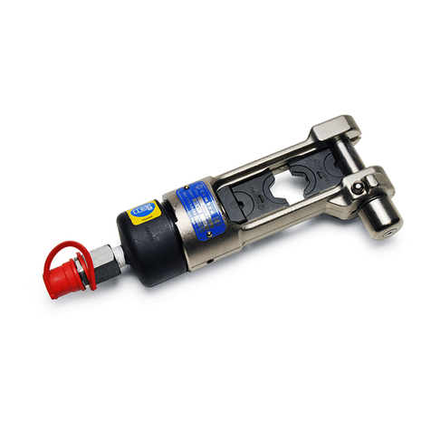
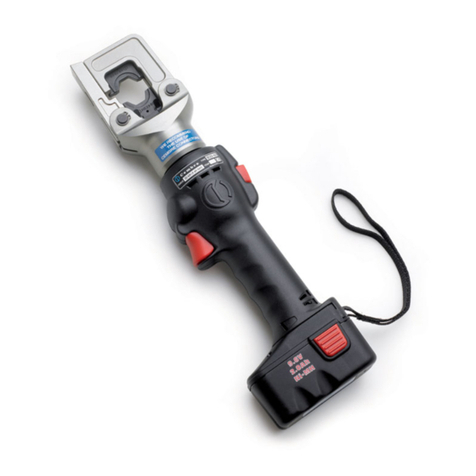
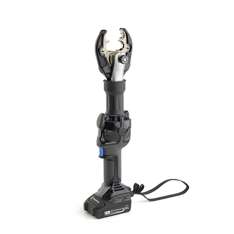
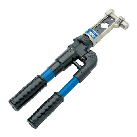
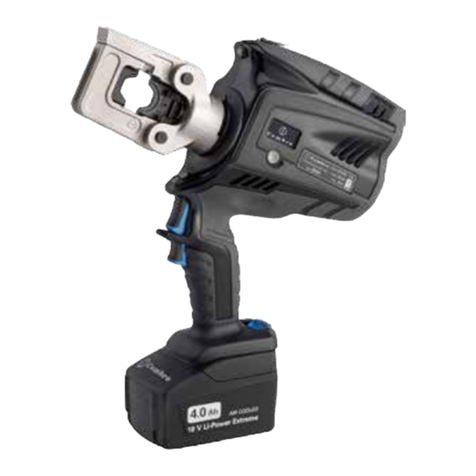
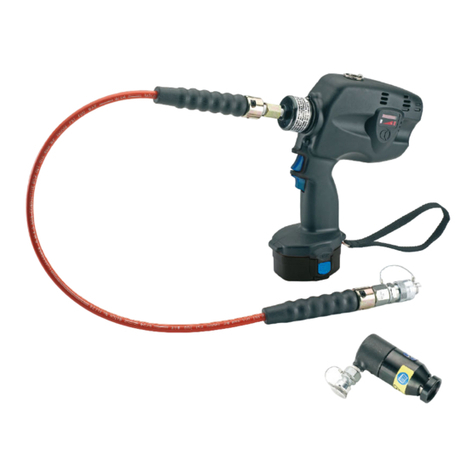
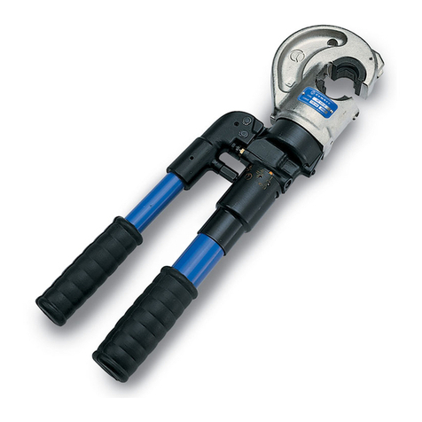
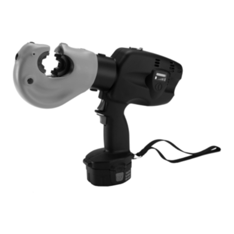
Cembre B450ND-BV User manual

1
BATTERY OPERATED HYDRAULIC CRIMPING TOOL
OUTIL HYDRAULIQUE DE SERTISSAGE SUR BATTERIE
HYDRAULISCHES AKKU-PRESSWERKZEUG
HERRAMIENTA HIDRÁULICA DE CRIMPADO A BATERÍA
UTENSILE OLEODINAMICO DA COMPRESSIONE A BATTERIA
B450ND-BV B450ND-BVA B450ND-BVE B450ND-BVT
ENGLISH
FRANÇAIS
DEUTSCH
ESPAÑOL
ITALIANO
OPERATION AND MAINTENANCE MANUAL....................................5
NOTICE D’UTILISATION ET ENTRETIEN........................................... 10
BEDIENUNGSANLEITUNG................................................................... 15
MANUAL DE USO Y MANTENIMIENTO ........................................... 20
MANUALE D’USO E MANUTENZIONE............................................. 25
18 M 127

2
FIG. / BILD 2
FIG. / BILD 3
FIG. / BILD 4 FIG. / BILD 5
3
Connector
Connecteur
Kabelschuh
Conector
Connettore
Battery
Batterie
Akku
Batería
Batteria
7
5
9
12
10 11
FIG. / BILD 1
PA ...
MA ...
3
Low battery
Batterie déchargée
Akku leer
Batería descargada
Batteria scarica
2

3
1
HEAD / TETE / KOPF / CABEZA / TESTA
2
4 LEDWORKLIGHT / ECLAIRAGE PAR LED / LED-BELEUCHTUNG / LUCES LED / ILLUMINAZIONE LED
3
OPERATING BUTTON / GACHETTE DE COMMANDE / STARTKNOPF / BOTÓN DE ACCIONAMIENTO
/ PULSANTE DI AZIONAMENTO
4
BATTERY / BATTERIE / AKKU / BATERÍA / BATTERIA
5
PRESSURE RELEASE BUTTON / GACHETTE DE DECOMPRESSION / DRUCKABLASSKNOPF / BOTÓN
DESBLOQUEO PRESIÓN / PULSANTE SBLOCCO PRESSIONE
6
HANDLE / POIGNEE / GRIFF / EMPUÑADURA / IMPUGNATURA
7
BATTERY RELEASE / DEBLOCAGE BATTERIE / AKKU ENTRIEGELUNG / DESBLOQUEO BATERÍA /
SBLOCCO BATTERIA
8
WRIST STRAP / DRAGONNE / HANDGURT / CORREA PARA LA MUÑECA / CINTURINO DA POLSO
FIG. / BILD 6
3
4
2
1
8
7
6
5

4
– Before using the tool, carefully read the instructions in this manual.
– Avant d'utiliser cet outil, lire attentivement les instructions de cette notice.
– Vor Inbetriebnahme unbedingt die Bedienungsanleitung durchlesen.
– Antes de utilizar la herramienta, leer atentamente las instrucciones en este manual.
– Prima di utilizzare l'utensile, leggere attentamente le istruzioni riportate in questo manuale.
– When operating the tool, keep hands away from the danger zone.
– Au cours du sertissage, tenir les mains éloignées de la zone de travail.
– Während des Verpressens nicht mit den Händen in den Pressbereich gelangen.
– Durante su utilización, mantenga las manos fuera de la zona de peligro.
– Durante l'utilizzo, mantenere le mani fuori dalla zona di pericolo.
– Always close the tool head correctly and securely.
– S'assurer toujours de la parfaite fermeture de la tête.
– Immer darauf achten, dass der Kopf richtig verriegelt ist.
– Asegurarse siempre de que la cabeza está correctamente cerrada.
– Assicurarsi sempre della perfetta chiusura della testa.
WARNING SYMBOLS - SYMBOLES D'AVERTISSEMENT - WARNSYMBOLE -
SÍMBOLOS DE ADVERTENCIA - SIMBOLI DI AVVERTENZA
TG.0932
TG.0932
– Never throw batteries into fire or water.
– Jamais jeter les batteries dans le feu ou dans l'eau.
– Werfen Sie Akkus nicht ins Feuer oder Wasser.
– Nunca tire las baterías al fuego o al agua
– Mai gettare le batterie nel fuoco o in acqua.
– Always recycle the batteries.
– Recycler toujours les batteries.
– Verbrauchte Akkus stets dem Recycling zuführen.
– Reutilizar siempre las baterías.
– Riciclare sempre le batterie.
– Do not discard batteries into domestic refuse or waste disposal.
– Ne pas jeter de batteries dans une poubelle ou autre lieu non prévu à cet effet.
– Verbrauchte Akkus nicht der allgemeinen Abfallentsorgung zuführen.
– No tirar las baterías al cubo de basura o lugar parecido.
– Non buttate le batterie fuori uso nei cestini della spazzatura o luoghi simili.
– User information (Directives 2011/65/EU and 2012/19/EU), see page 30.
– Information pour les utilisateurs (Directives 2011/65/EU et 2012/19/EU) voir page 30.
– Information für den Benutzer (Richtlinien 2011/65/EU und 2012/19/EU) siehe Seite 30.
– Informe para los usuarios (Directivas 2011/65/EU y 2012/19/EU) vease página 30.
– Informazione agli utenti (Direttive 2011/65/EU e 2012/19/EU) vedere pagina 30.
TG.0932
TG.0932
TG.0932
TG.0932
Battery - Batterie - Akku - Batería - Batteria
Tool - Outil - Werkzeug - Herramienta - Utensile
5
(1) Directive 2006/42/EC, annexe 1, point 1.7.4.2 letter u
LpA = weighted continuous acoustic pressure level equivalent.
LpCPeak = maximum value of the weighted acoustic displacement pressure at the work place.
LWA = acoustic power level emitted by the machine.
(2) Directive 2006/42/EC, annexe 1, point 2.2.1.1
Weighted root mean square in frequency of the acceleration the upper limbs are exposed to for each biodynamic
reference axis. Tests carried out in compliance with the indications contained in EN ISO 5349-1/2 Standard, and under
operating conditions much more severe than those normally found.
1. GENERAL CHARACTERISTICS
ENGLISH
B450ND-BV
B450ND-BVE
B450ND-BVT
B450ND-BVA
Application range suitable for installing electrical compression connectors on
conductors up to 150 mm2(300 MCM)
Rated crimping force
kN (US sh. ton)
50 (6)
Minimum operating pressure
bar (psi) 600 (8702)
Dimensions mm (inches) 364 x 136 x 81 (14.3 x 5.3 x 3.2)
Weight with battery kg (lbs) 2,6 (5.7)
Motor V DC 18
Operating temperature °C (°F) -15 to +50 (+5 to +122)
Recommended oil TOTAL DIEKAN 1640 or equivalents
Operating speed twin speed operation and automatic switching from a rapid
advancing speed of the ram to a slower, more powerful
crimping speed
Safety maximum pressure valve
Rechargeable battery V / Ah / Wh 18 / 2.0 / 36
Type CB1820L (Li-Ion)
Weight kg (lbs) 0,4 (0.9)
Battery charger
ASC30-36
Input
type EU
37334000
UK
27045000
AUS/NZ
27047000
USA/CAN
37401000
V / Hz 220 - 240 / 50 - 60 115 / 60
W 85
Acoustic noise (1)
LpA dB (A)
67,7
LpCPeak dB (C) 89,2
LWA dB (A) 74,2
Vibration (2) m/s2ahv 0,724

6
ENGLISH
WARNING
Do not use the tool for purposes other than those intended by Cembre.
The operator should concentrate on the work being performed and be careful to
maintain a balanced working position.
Before starting work on electrical equipment, please ensure that either there are
no live parts in the immediate working area or that precautions are taken for
working near live parts in accordance with EN50110-1.
Do not use this tool on or near live conductors without proper personal protective
equipment. Failure to observe this warning could result in severe injury or death.
The tool is unsuitable for continuous use and should be allowed to cool down fol-
lowing uninterrupted, successive crimping operations. For example, having ex-
hausted a fully charged battery in one session, delay battery replacement for a
few minutes.
Protect the tool from rain and moisture. Water will damage the tool and battery.
Electro-hydraulic tools should not be operated in pouring rain.
2. INSTRUCTIONS FOR USE
IMPORTANT: In order to avoid damaging the tool, do not operate at maximum
pressure, without dies inserted in the head.
When introducing or changing dies, the battery must first be removed from the tool.
The part reference includes the following:
Hydraulic crimping tool.
Li-Ion rechargeable battery.
Battery charger (model depends on the tool version).
Shoulder strap.
Plastic carrying case.
USB cable (Ref. to section 4).
2.1) Preparation
The tool can be easily carried using either the main handle (6) or the shoulder strap attached to the
two eyelets of the wrist strap (8) (Ref. to FIG. 6).
The tool can be held in one hand while positioning the conductor with the other.
Before starting any work, check the battery charge (Ref. to section 2.7) and recharge if
necessary, following the instructions in the battery charger user manual.

7
ENGLISH
terminal
connector
123
12
1
3
2
3
conductor
conductor
To replace the battery, remove it by pressing the release button (7) (Ref. to Fig. 1), then insert the
new battery, sliding it into the guides until it locks.
Select the appropriate die set for the connector.
Open the latch (9) and release the upper die holder (10) (Ref. to Fig. 2).
Insert one die into the upper die holder (10) until locked by the ball (12) and one die into the
lower die support (11) until locked by the ball (12).
For indent crimping, the nest MA... must be inserted in to the upper die holder (10), and the
indentor PA... must be inserted into the lower die support (11) (Ref. to Fig. 2).
Close the head.
Insert the conductor into the connector (Ref. to Fig. 3).
Position the connector between the dies and ensure the correct location of the crimp (Ref. to
Fig. 4).
NOTE: when more than one com-
pression is required, proceed
according to the sequence and
direction indicated in the figure
opposite.
Ensure that the latch and the upper die holder are fully secured, otherwise damage
may occur during tool operation.
2.2) Die advancement
Press operating button (3) (Ref. to Fig. 4) to activate the motor-pump and advance the
lower die.
To halt the advancement, release operating button (4) and the motor will cut out.
Make sure the dies are exactly positioned on the desired crimp point otherwise
re-open dies following instructions as per section 2.4 and reposition the connector.
2.3) Compression
By keeping the operating button (3) pressed, the motor continues to operate and the ram will
gradually move forward until the two dies touch.
The motor will stop automatically when the set pressure has been reached.
To perform a full compression, press and hold the operating button (3) until the
motor stops automatically.

8
ENGLISH
2.4) Release of dies
By operating the pressure release button (5) (Ref. to Fig. 4), the ram will retract and open the dies.
2.5) LED Worklights
Whilst the tool is in operation, the compression area is illuminated by four high luminosity LED
Worklights that switch off automatically at the end of the cycle.
2.6) Head rotation
For ease of operation, the tool head can rotate through 180°, allowing the operator to
work in the most comfortable position.
Do not attempt to rotate the head when the hydraulic circuit is pressurised.
2.7) Battery status
The battery is equipped with LED indicators that indicate the
remaining battery life at any time by pressing the adjacent
button (P):
4 LEDs illuminated: fully charged
2 LEDs illuminated: 50 % capacity
1 LED flashing: minimum charge, replace the battery
Illuminated worklights (2) (Ref. to Fig. 5) combined with an audible alarm when the opera-
ting button (3)
is pressed, indicate that the battery voltage has dropped below a minimum
safetythreshold;
undertheseconditionsthetoolwillnotstart,anditisnecessarytorecharge
or replace the battery.
The approximate time to fully recharge a battery is about 40 minutes.
2.8) Using the battery charger
Carefully follow the instructions in the battery charger user manual.
3. MAINTENANCE
The tool is robust, completely sealed, and requires very little daily maintenance. Compliance with
the following points, should help to maintain its optimum performance:
3.1) Thorough cleaning
Dust, sand and dirt are a danger for any hydraulic device.
Every day, after use, the tool must be wiped with a clean cloth taking care to remove any residue,
especially close to pivots and moveable parts.
Do not use hydrocarbons to clean the rubber parts.
P

9
ENGLISH
3.2) Storage case
When not in use, the tool should be stored and
transported in the plastic case supplied to pre-
ventdamage.Thecase,typeVAL-P22,issuitable
for storing the tool, the accessories, up to 9 die
setsandpre-preparedcompressionconnectors.
VAL-P22: Size 465x315x116 mm (18.3x12.4x4.6
inches). Weight 1,5 kg (3.3 lbs).
3.3) Routine maintenance
Whenthetoolreachesthepredeterminednumberofhoursworked,
it will signal via an audible alarm that routine maintenance is
recommended.
The tool will continue to work, however 15 sec. after use an alarm comprising 3 beeps combined
withilluminationoftheworklights(2)willsignalthatitsreturntoCembreforserviceisrecom-
mended (see section 5).
4. CONNECTION TO COMPUTER
Thememorycardintegratedinthetoolrecordsoperatingdata fortransferviatheUSBcablesupplied.
To view and manage this data, go to www.cembre.com and register in the dedicated area, then
download the free Cembre software CEM_SWBT01.
Keeping the Firmware of the tool updated, via free of charge download, will optimise the tool's
performance.
5. RETURN TO Cembre FOR OVERHAUL
In the case of a breakdown contact our Area Agent who will advise you on the problem and give
you the necessary instructions on how to dispatch the tool to our nearest service Centre; if possible,
attach a copy of theTest Certificate supplied by Cembre together with the tool or fill in and attach
the form available in the“ASSISTANCE” section of the Cembre website.

10
1. CARACTERISTIQUES GENERALES
B450ND-BV
B450ND-BVE
B450ND-BVT
B450ND-BVA
Domaine d'application: conçu pour le sertissage des connecteurs électriques jusqu'
à 150 mm2(300 MCM)
Force nom. de sertissage
kN (US sh. ton)
50 (6)
Pression min. de travail bar (psi) 600 (8702)
Dimensions mm (inches) 364 x 136 x 81 (14.3 x 5.3 x 3.2)
Poids avec batterie kg (lbs) 2,6 (5.7)
Moteur V DC 18
Température de fonction-
nement: °C (°F) -15 à +50 (+5 à +122)
Huile recommandée: TOTAL DIEKAN 1640 ou équivalents
Avance rapide:
l’outil passe automatiquement de la vitesse rapide d’appro-
che des matrices à la vitesse lente de sertissage
Sécurité valve de surpression
Batterie rechargeable V / Ah / Wh 18 / 2.0 / 72
Type CB1820L (LI-Ion)
Poids kg (lbs) 0,4 (0.9)
Chargeur de batterie
ASC30-36
Alimentation
type EU
37334000
UK
27045000
AUS/NZ
27047000
USA/CAN
37401000
V / Hz 220 - 240 / 50 - 60 115 / 60
W 85
Bruit aérien sonore (1)
LpA dB (A) 67,7
LpCPeak dB (C) 89,2
LWA dB (A) 74,2
Vibrations (2) m/s2ahv 0,724
(1) Directive 2006/42/CE, annexe 1, point 1.7.4.2, lettre u
LpA = niveau de pression sonore continue équivalente pondérée A sur le poste de travail.
LpCPeak = valeur de pression sonore instantanée pondérée C sur le poste de travail.
LWA = niveau de puissance acoustique dégagée par la machine.
(2) Directive 2006/42/CE, annexe 1, point 2.2.1.1
Valeurquadratique moyenne pondéréeenfréquence de l'accélérationàlaquelle sont exposéslesmembres supérieurs
pour chaque axe biodynamique de référence. Relevés réalisés suivant les indications de la Norme EN ISO 5349-1/2,
dans des conditions de service largement représentatives des conditions d'emploi normales.
FRANÇAIS

11
AVERTISSEMENT
Ne pas utiliser cet outil à des fins différentes que celles prévues par le constructeur.
Restez bien attentif tout au long du travail, ne soyez pas distrait, ne perdez pas
l’équilibre pendant l'utilisation.
Avant d’entreprendre des travaux sur des équipements électriques, veuillez vous
assurer qu’aucun élément aux abords de la zone de travail n’est sous tension.
Dans le cas contraire, veuillez prendre les précautions nécessaires pour opérer à
proximité d’éléments sous tension, en conformité avec la norme EN50110-1.
Ne pas utiliser cet outil sur ou à côté de conducteurs sous tension, sans protection
individuelle adéquate. La non observation de cette précaution peut provoquer
des lesions graves ou mortelles.
L’outil n’est pas conçu pour une utilisation en continu; après avoir effectué une
quantité de sertissages consécutifs à partir d’une batterie complètement chargée,
au moment du remplacement de la batterie, nous suggérons d'observer une période
d’arrêt pour permettre le refroidissement de l’outil.
Protéger l’outil de la pluie et de l’humidité. L’eau pourrait endommager l’outil et la
batterie, les outils hydroélectriques ne devraient pas être utilisés sous la pluie.
2. INSTRUCTIONS D'UTILISATION
IMPORTANT: Pour éviter d’endommager l’outil, il est déconseillé de l’actionner à
vide et à la pression maximale, sans avoir inséré les matrices dans la tête.
Les opérations d’introduction ou de remplacement des matrices doivent être
effectuées avec l’outil dépourvu de batterie.
L' ensemble comprend:
Outil hydraulique de sertissage.
Batterie rechargeable Li-Ion.
Chargeur de batterie (différent en fonction de la version de l'outil).
Bandoulière.
Coffret de rangement.
Câble USB (Voir § 4).
2.1) Mise en service
L'outil peut être facilement transporté en utilisant la poignée principale (6) ou la bandoulière fixée
aux deux oeillets de la dragonne (8) (Voir Fig. 6).
L'outil peut être tenu dans une main tout en positionnant le conducteur avec l'autre.
Avant de commencer toute opération, contrôler l’état de charge de la batterie (voir § 2.7)
et, si nécessaire, la recharger en suivant les instructions contenues dans le manuel d’utili-
sation du chargeur de batteries.
FRANÇAIS

12
Pour remplacer la batterie, la retirer en appuyant sur le mécanisme de déblocage (7)
(voir Fig. 1), puis introduire la nouvelle batterie en la faisant coulisser sur les guides
jusqu’au blocage complet.
Choisir le couple de matrices approprié pour le type de connexion à réaliser; pour cela,
consulter le catalogue.
Ouvrir la tête de l'outil en écartant le crochet (9), libérant ainsi le porte matrice supérieur
(10) qui s'écartera complètement (Voir Fig. 2).
Insérer les matrices dans leur logement respectif dans le porte matrice supérieur (10)
jusqu'à ce qu'il soit verrouillé par la bille (12) et dans le support de matrice inférieure (11) jusqu'à
ce qu'il soit verrouillé par la bille (12).
Il est à considérer que lors de sertissage par poinçonnage, le poinçon PA.. doit être placé dans
le porte matrice inférieur (11) et la matrice MA... doit être positionnée dans le porte matrice
supérieur (10) (Voir Fig. 2).
Refermer la tête.
Insérer le conducteur dans le connecteur (Voir Fig. 3).
Positionner ce dernier entre les deux matrices en alignant la zone à sertir avec l'empreinte
des matrices (Voir Fig. 4).
REMARQUE: s’il est nécessaire de
procéder à plusieurs sertissages
de cosses ou de manchons, suivre
laséquenceet la directionreportée
sur l’illustration en espaçant les
empreintes de façon uniforme.
Avant de poursuivre les
opérations, vérifier que
la tête soit parfaitement fermée.
2.2) Avance des matrices
Appuyer sur la gâchette de commande (3) (Voir Fig. 4) pour mettre en marche le groupe
moteur pompe; les matrices commencent alors à se rapprocher du connecteur.
La gâchette de commande (3) relâchée, le moteur et l'avance des matrices cessent im-
médiatement.
S
S'assurer que les matrices sont bien positionées sur la zone à sertir, sinon desserer
les matrices en suivant les instructions du § 2.4 et repositioner le connecteur.
2.3) Sertissage
En maintenant pressée la gâchette de commande (3), on maintient la rotation du moteur;
le piston avance progressivement jusqu'à ce que les matrices arrivent en butée l'une
contre l'autre.
L’outil s’arrêtera automatiquement dès qu’il aura atteint la pression de tarage.
Pour effectuer un bon sertissage, maintenir la gâchette de commande (3) pressée
jusqu’à l’arrêt automatique du moteur.
cosse
manchon
123
12
1
3
2
3
conducteur
conducteur
FRANÇAIS

13
FRANÇAIS
2.4) Réouverture des matrices
En appuyant à fond sur la gâchette de déblocage pression (5) (Voir Fig. 4), on provoque le retour
du piston et par conséquent l'ouverture des matrices.
2.5) Led
Lors de l’actionnement de l’outil, la zone de sertissage est éclairée au moyen de quatre LED haute
luminosité qui s’éteignent automatiquement à la fin du cycle.
2.6) Rotation de la tête
La tête de l'outil pivote de 180° par rapport au corps, permettant à l'utilisateur de travailler dans la
meilleure position.
Ne pas forcer la rotation de la tête, lorsque le circuit hydraulique est sous pression.
2.7) Autonomie de la batterie
La batterie est équipée d’indicateurs à LED qui permettent de
contrôler, à tout moment, son autonomie résiduelle en
appuyant sur le bouton (P):
4 led allumées: autonomie maximale
2 led allumées: autonomie à 50 %
1 led clignotante: autonomie minimale, remplacer la batterie.
L'éclairage des Led (2) associé à l’avertisseur sonore lorsqu'on appuie sur la gâchette de
commande (3) (Voir Fig. 5) indique que la batterie est déchargée et que sa tension est
descendue au-dessous du seuil minimal de sécurité; dans cette situation, l’outil ne démarre
pas, il est donc nécessaire de recharger ou de remplacer la batterie.
À titre indicatif, le délai de recharge complète de la batterie correspond à environ 40 min.
2.8) Utilisation du chargeur de batterie
Suivre attentivement les instructions indiquées sur le manuel.
3. ENTRETIEN
L'outil est robuste, complètement scellé et ne nécessite aucune préoccupation ou attention parti-
culière. Les recommandations qui suivent sont néanmoins souhaitables pour assurer une longévité
optimum:
3.1) Nettoyage élémentaire
Veiller à protéger l'outil de la poussière, du sable et de la boue qui sont un danger à tout système
hydraulique. Chaque jour après utilisation, l'outil doit être nettoyé à l'aide d'un chiffon propre, tout
particulièrement aux endroits de pièces mobiles.
Ne jamais utiliser d’hydrocarbures pour le nettoyage des parties en caoutchouc.
P

14
3.2) Rangement
Au repos, pour protéger l'outil des coups ac-
cidentels et de la poussière, il convient de le
rangerdanslecoffret.Cecoffret(typeVAL-P22),
adapté pour contenir l'outil, ses accessoires
et 9 paires de matrices a comme dimensions:
465x315x116 mm (18.3x12.4x4.6 inches) et un
poids de 1,5 kg (3.3 lbs).
3.3) Entretien de routine
Lorsqu'on atteint le nombre prédéterminé d'heures de travail,
l'outil va signaler la nécessité d'effectuer l'entretien de routine.
Après 15 secondes de l'exécution du dernier cycle, la nécessité de procéder à l'entretien de
routine est signalée par allumages intermittents répétés trois fois des LED (2) associé à
l’avertisseur sonore. L'outil continue par ailleurs à travailler normalement; mais il est re-
commandé de le renvoyer à Cembre pour une révision complète (voir § 5).
4. CONNEXION À L’ORDINATEUR
Le fichier de mémoire intégrée dans l’outil permet d’enregistrer les paramètres de fonctionnement
etde pouvoirles transférer versun ordinateur parl’intermédiaire du câble USBfourni.Pourvisualiser
et gérer les données mémorisées, le logiciel Cembre CEM_SWBT01 est disponible gratuitement
aprèsenregistrementdans ledomaine réservé dusite www.cembre.com.Dans cedomaine réservé,
il sera alors possible de trouver les mises à jour éventuelles des firmwares permettant à vos propres
outils une meilleure efficacité et d’améliorer leurs performances.
5. ENVOI EN REVISION A Cembre
En cas de dysfonctionnement de l’appareil, merci de vous adresser à notre Agent Régional qui vous
conseillera et le cas échéant vous donnera les instructions nécessaires pour envoyer l’appareil à
notre Centre de Service le plus proche. Dans ce cas, joindre une copie du Certificat d’Essai livré par
Cembre avec l’appareil ou remplir et joindre le formulaire disponible dans la section“ASSISTANCE”
du site web Cembre.
FRANÇAIS

15
DEUTSCH
1. ALLGEMEINE EIGENSCHAFTEN
(1) Richtlinie 2006/42/EG, Anhang 1, Nummer 1.7.4.2, Buchstabe u
LpA = Stufe konstanter Emissionsschalldruckpegel entsprechend Gewichtung A am Arbeitsplatz.
LpCPeak = maximaler Emissionsschalldruckpegel entsprechend Gewichtung C am Arbeitsplatz.
LWA = Emissionsschalldruckpegel durch das Gerät
(2) Richtlinie 2006/42/EG, Anhang 1, Nummer 2.2.1.1
Der durchschnittliche Schwingungsgesamtwert dem die oberen Körpergliedmaßen ausgesetzt sind, wurde tech-
nisch vergleichbar nach EN ISO 5349-1/2 an einer repräsentativen Maschine ermittelt und übersteigt nicht den
vorgeschriebenen Wert.
B450ND-BV
B450ND-BVE
B450ND-BVT
B450ND-BVA
Anwendungsbereich GeeignetzumVerpressenvonVerbindernundKabelschuhen
bis zu einem Querschnitt von max. 150 mm2(300 MCM)
Nennpreßkraft
kN (US sh. ton)
50 (6)
Minimaler Arbeitsdruck bar (psi) 600 (8702)
Abmessungen mm (inches) 364 x 136 x 81 (14.3 x 5.3 x 3.2)
Gewicht inkl. Akku kg (lbs) 2,6 (5.7)
Motor V DC 18
Betriebstemperatur: °C (°F) -15 bis +50 (+5 bis +122)
Empfohlenes Öl: TOTAL DIEKAN 1640 oder ähnliches
Kolbenvorschub:
Das Werkzeug ist mit einer Doppelkolbenhydraulik aus-
gerüstet, die ein schnelles Zusammenfahren der Press-
einsätze ermöglicht. Beim Beginn des Pressvorganges wird
auf den langsameren Arbeitshub umgeschaltet
Sicherheit: Überdruckventil
Wiederaufladbarer Akku V / Ah / Wh 18 / 2.0 / 36
Typ CB1820L (Li-Ionen)
Gewicht kg (lbs) 0,4 (0.9)
Akkuladegerät
ASC30-36
Spannung
Typ EU
37334000
UK
27045000
AUS/NZ
27047000
USA/CAN
37401000
V / Hz 220 - 240 / 50 - 60 115 / 60
W 85
Lärmschutzbestimmung (1)
LpA dB (A)
67,7
LpCPeak dB (C) 89,2
LWA dB (A) 74,2
Vibrationen (2) m/s2ahv 0,724

16
HINWEISE
Verwenden Sie das Akkuwerkzeug ausschließlich für den vom Hersteller vorgese-
henen Anwendungszweck.
Arbeiten Sie konzentriert und lassen Sie sich während des Einsatzes nicht ablenken.
Nehmen Sie zur Arbeit eine sichere und standfeste Arbeitsposition ein!
Vor Beginn der Arbeiten an elektrischen Anlagen ist sicherzustellen, dass sich keine
spannungsführenden Teile in unmittelbarer Nähe des Arbeitsbereiches befinden.
Ansonsten notwendige Vorsichtsmaßnahmen entsprechend der Norm EN 50110-1
vornehmen, um den Arbeitsbereich abzusichern.
Dieses Werkzeug nicht ohne ausreichende Schutzmaßnahmen an oder in der Nähe
von stromführenden Leitungen verwenden! Eine Nichtbeachtung von Schutz-
maßnahmen, kann zu Verletzungen oder zum Tode führen.
Die Akkuwerkzeuge sind nicht für einen Dauereinsatz geeignet. Wenn ein voll
geladener Akku durch hintereinander ausgeführte Verpressungen ausgetauscht werden
muss, empfehlen wir vor dem Akkuwechsel, das Werkzeug eine angemessene Zeit
abkühlen zu lassen.
Das Werkzeug vor Regen und Feuchtigkeit schützen. Wasser könnte das Werkzeug
und den Akku beschädigen. Elektrohydraulische Werkzeuge sollten nicht im Regen
eingesetzt werden.
2. BEDIENUNGSHINWEISE
WICHTIG: Um Schäden an dem Werkzeug zu vermeiden, sollte es nie mit Maximaldruck,
ohne Pressmaterial und ohne eingesetzte Presseinsätze betätigt werden.
Das Einsetzen und/oder der Wechsel der Presseinsätze, muss immer mit ausgebautem
Akku erfolgen.
Zum Lieferumfang gehören folgende Teile:
Hydraulisches Akkupresswerkzeug.
Wiederaufladbare Li-Ion Akku.
Ladegerät (entsprechend der Länderkonfiguration).
Trageriemen.
Kunststoffkoffer.
USB-Kabel (siehe Punkt 4).
2.1) Vorbereitung
Das Werkzeug kann bequem getragen werden, entweder am Griff (6), oder indem derTrageriemen
an den zwei Ringen des Handgurtes (8) angebracht wird (siehe Bild 6).
Das Werkzeug kann in einer Hand gehalten werden, während der Leiter mit der anderen Hand
positioniert wird.
ÜberprüfenSie vor jedem Arbeitsvorgang den Ladezustand der Akkus (siehe Pkt. 2.7).
Um die Akkus aufzuladen, folgen Sie den Anweisungen des Akkuladegerätes in der
Bedienungsanleitung.
DEUTSCH

17
DEUTSCH
Drücken Sie für den Akkuaustausch auf die Entriegelung (7) (siehe Bild 1) und führen
Sie den neuen Akku bis zum Einrasten ein.
Passendes Presseinsatz Paar auswählen.
Öffnen Sie den Kopf der Akkupresse am Haken (9) und der obere Presseinsatzhalter
(10) kann weit geöffnet werden (siehe Bild 2).
Setzen Sie die Presseinsätze in die vorgesehene Halterung ein: den oberen Presseinsatz
in den Presseinsatzhalter (10) bis die Kugel (12) einrastet, den unteren in den Presseinsatzhalter
(11) bis die Kugel (12) einrastet.
Im Fall einer Dornverpressung muss der Dorneinsatz PA... in den unteren Preßeinsatzhalter
(11) eingefügt werden. Der Preßeinsatz MA... muß dementsprechend in den oberen Preßein-
satzhalter (10) montiert werden (siehe Bild 2).
Schließen Sie den Presskopf.
Den zu verpressenden Leiter in den Verbinder oder Kabelschuh einlegen (siehe Bild 3).
Positionieren Sie den Verbinder oder Kabelschuh an der vorgeschriebenen Position am
Presseinsatz (siehe Bild 4).
ANMERKUNG: Beim Verpressen
von Kabelschuhen oder Verbindern,
gehen Sie bei mehreren erforderli-
chen Pressvorgängen, gemäß der
in der Abbildung angegebenen
Reihenfolge und Richtung vor.
Lassen Sie einen gleichmäßigen
Abstand zwischen den verschiedenen
Verpressungen.
Vor Inbetriebnahme des Werkzeuges muss der Kopf vollständig geschlossen sein,
sonst kann es zu Beschädigungen kommen.
2.2) Positionierung
Durch Drücken des Startknopfes (3) (siehe Bild 4) beginnen Motor und Pumpe zu ar-
beiten und die Presseinsätze nähern sich dem Verbinder oder Kabelschuh.
Sobald der Startknopf (3) wieder losgelassen wird, halten Motor und Kolben sofort an.
S
Die Presseinsätze müssen in die gewünschte Position am Verbinder oder Kabelschuh
positionert werden. Sollte dies nicht der Fall sein, muss das Werkzeug entsprechend
Pkt. 2.4 geöffnet werden und es kann neu positioniert werden.
2.3) Verpressung
Wird der Startknopf (3) weiter gedrückt, fahren die Presseinsätze langsam aufeinander
zu und die Verpressung wird durchgeführt.
Das Werkzeug hält bei Erreichen des eingestellten Druckes automatisch an.
Für einen korrekten Pressvorgang, halten Sie den Startknopf bis zum automatischen
Abschalten des Motors gedrückt.
Kabelschuh
Verbinder
123
12
1
3
2
3
Leiter
Leiter

18
DEUTSCH
2.4) Öffnen der Presseinsätze
Drücken Sie kräftig den Druckablassknopf (5) (siehe Bild 4). Dadurch fährt der Kolben zurück und
die Presseinsätze geben den Kabelschuh / Verbinder frei.
2.5) LED
Während der Betätigung des Werkzeuges, wird der Pressbereich von vier LED-Leuchten mit hoher
Leuchtkraft ausgeleuchtet, die sich am Zyklusende automatisch abschalten.
2.6) Drehbewegung des Kopfes
Das Werkzeug ist mit einem Kopf ausgerüstet, der um 180° drehbar ist und somit ein komfortables
Arbeiten ermöglicht.
Der Kopf sollte keinesfalls in eine andere Position gedreht werden, während die
Presseinsätze unter Druck stehen.
2.7) Akkuladung
Die Akku ist mit LED-Anzeigen ausgestattet, die jederzeit über die
verbleibende Akkulaufzeit Auskunft gibt, indem man auf dieTaste
(P) drückt:
4 LED eingeschaltet: Maximale Ladung
2 LED eingeschaltet: Ladung zu 50 %
1 LED blinkend: Minimale Ladung, Akku austauschen bzw.
aufladen.
Wenn der Akku nicht mehr ausreichende Ladung hat, wird beim Betätigen des
Startknopfes(3) über die LED (2) Leuchten zusammen mit einem akustischen Signal
(siehe Bild 5) das Erreichen des Mindestsicherheitsniveau signalisiert. Unter diesen
Bedingungen kann das Werkzeug nicht in Betrieb genommen werden. Laden Sie den Akku
auf oder tauschen Sie ihn aus.
Ein vollständiger Ladevorgang eines leeren Akkus dauert etwa 40 Minuten.
2.8) Verwendung des Ladegerätes
Die in der Bedienungsanleitung aufgeführten Hinweise sind zu beachten.
3. WARTUNG
Das Werkzeug ist robust und benötigt keine spezielle Pflege.
Zur Erhaltung der Garantieansprüche beachten Sie folgende Hinweise:
3.1) Pflege
Dieses hydraulische Werkzeug sollte vor starker Verschmutzung wie Staub, Sand oder Schmutz
geschützt werden, da dies für ein hydraulisches System gefährlich ist. Nach jeder täglichen Anwen-
dung sollte das Werkzeug mit einem Tuch von Schmutz und Staub gereinigt werden, besonders
die beweglichenTeile.Verwenden Sie keine Kohlenwasserstoffe (z.B.Teilereiniger, Bremsenreiniger)
zum Reinigen der Gummiteile.
P

19
DEUTSCH
3.2) Lagerung
Wird das Werkzeug nicht benötigt, sollte es
im Kunststoffkoffer gelagert werden, um es so
gegen Beschädigungen wie Stöße und Staub
zu schützen.
Der Kunststoffkoffer Typ VAL-P22 hat fol-
gende Abmessungen: 465x315x116 mm
(18.3x12.4x4.6 inches) und ein Gewicht von
1,5 kg (3.3 lbs).
Er ist geeignet zum Lagern von Werkzeug,
Zubehör, sowie 9 Presseinsatz Paaren.
3.3) Wartung
Sobald die vorgegebene Anzahl der maximalen
Arbeitsstunden erreicht sind, signalisiert das Werkzeug die damit fällige Wartung.
15 Sekunden nach Ausführung des letzten Zyklus, wird eine bevorstehende War-
tung,dreimal hintereinander durch ein unterbrechendes Aufblinken der LED's (2),
zusammen mit einem akustischen Warnsignal angekündigt.
Das Werkzeug wird weiterhin normal arbeiten. Es wird das Einsenden des Werkzeuges an
Cembre empfohlen, für eine komplette Überholung (siehe Pkt. 6).
4. ANSCHLUSS AN EINEN COMPUTER
Der imWerkzeug integrierte Speicher ermöglicht die Betriebsparameter zu speichern und mit dem
mitgelieferten USB-Kabel auf einen Computer zu übertragen.
Um die Daten vomWerkzeug zu übertragen und zu verwalten, müssen Sie unter www.cembre.com
die Cembre Software CEM_SWBT01 nach einer Registrieung downloaden.
Hier finden Sie auch mögliche Firmware Updates für die Platine desWerkzeuges, um eine bestmög-
liche Leistung und Effizienz des Werkzeuges zu ermöglichen.
5. EINSENDUNG AN Cembre ZUR ÜBERPRÜFUNG
Sollten an dem Gerät Fehler auftreten, wenden Sie sich bitte an unsere Gebietsvertretung, die
Sie gerne beraten und Ihnen alle nötigen Informationen zum Einsenden des Gerätes an unseren
Hauptsitz geben wird. Wenn vorhanden, legen Sie dem Gerät bitte eine Kopie des von Cembre
mitgelieferten Zertifikates bei oder füllen das, unter dem Bereich“SUPPORT“ der Cembre Website,
verfügbare Formular aus und fügen es bei.

20
1. CARACTERíSTICAS GENERALES
(1) Directiva Europea 2006/42/CE, anexo 1, punto 1.7.4.2, letra u
LpA = nivel de presión acústica contínua equivalente ponderado A en el puesto de trabajo.
LpCPeak = valor máximo de la presión acústica instantánea ponderada C en el puesto de trabajo.
LWA = nivel de potencia acústica emitida por la máquina.
(2) Directiva Europea 2006/42/CE, anexo 1, punto 2.2.1.1
Valor cuadrático medio ponderado en frecuencia, de la aceleración a la que están expuestos los miembros superiores
para cada eje biodinámico de referencia. Medidas realizadas según las indicaciones de la Norma EN ISO 5349-1/2, en
condiciones de utilización ampliamente representativas respecto a las que se encuentran normalmente.
B450ND-BV
B450ND-BVE
B450ND-BVT
B450ND-BVA
Campo de aplicación: para la instalación de conectores eléctricos por compresión
para conductores en general hasta 150 mm2(300 MCM) max
Fuerza nomin. de compresión
kN (US sh. ton)
50 (6)
Presión mínima de trabajo bar (psi) 600 (8702)
Dimensiones mm (inches) 364 x 136 x 81 (14.3 x 5.3 x 3.2)
Peso con batería kg (lbs) 2,6 (5.7)
Motor V DC 18
Temperatura de funciona-
miento °C (°F) -15 a +50 (+5 a +122)
Aceite recomendado TOTAL DIEKAN 1640 ó equivalentes
Velocidad de avance una rápida de aproximación de las matrices
al conector y otra más lenta de compresión
El paso de una a otra velocidad es automático
Seguridad válvula de sobrepresión
Batería recargable V / Ah / Wh 18 / 2.0 / 36
Tipo CB1820L (Li-Ion)
Peso kg (lbs) 0,4 (0.9)
Cargador de batería
ASC30-36
Alimentación
tipo EU
37334000
UK
27045000
AUS/NZ
27047000
USA/CAN
37401000
V / Hz 220 - 240 / 50 - 60 115 / 60
W 85
Ruido aéreo (1)
LpA dB (A) 67,7
LpCPeak dB (C) 89,2
LWA dB (A) 74,2
Vibraciones (2) m/s2ahv 0,724
ESPAÑOL
This manual suits for next models
3
Table of contents
Languages:
Other Cembre Power Tools manuals

Cembre
Cembre B1300-UC User manual

Cembre
Cembre B35-TC025 User manual

Cembre
Cembre B-TC950A User manual

Cembre
Cembre B135-UC User manual

Cembre
Cembre PNB-3 Series User manual

Cembre
Cembre RHU131 User manual

Cembre
Cembre B550 User manual

Cembre
Cembre HT120 User manual

Cembre
Cembre RHU450 User manual

Cembre
Cembre RHU520 User manual

Cembre
Cembre RHU81-D User manual

Cembre
Cembre MTE1-S User manual

Cembre
Cembre B540ND User manual

Cembre
Cembre B-TC500Y User manual

Cembre
Cembre B135-C-KV User manual

Cembre
Cembre BTEPE2.DET10 User manual

Cembre
Cembre RHU600 User manual

Cembre
Cembre HT120-KV User manual

Cembre
Cembre B-TD270 User manual

Cembre
Cembre B51 User manual