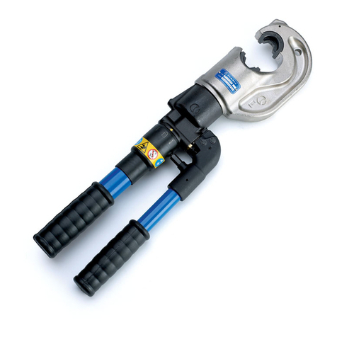
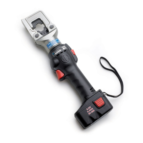
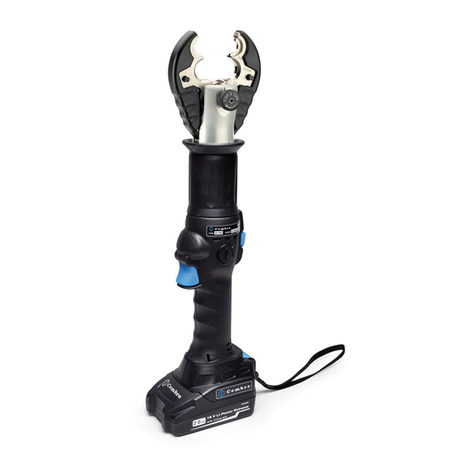
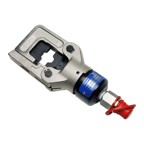
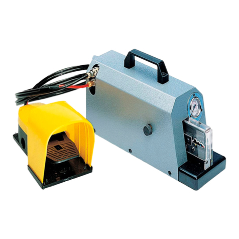
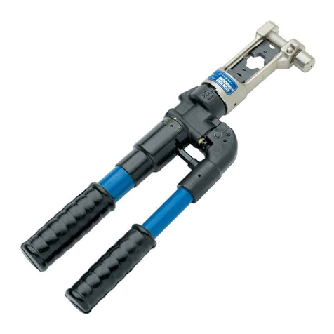
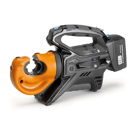
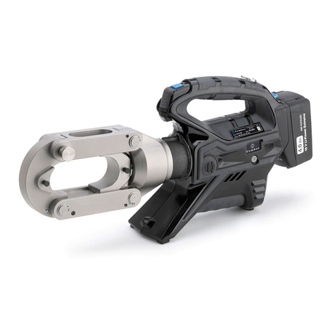
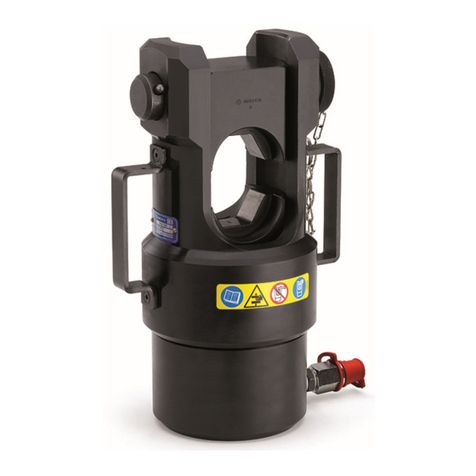
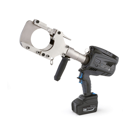
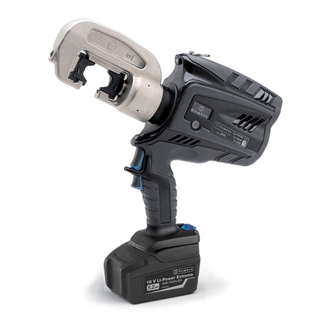
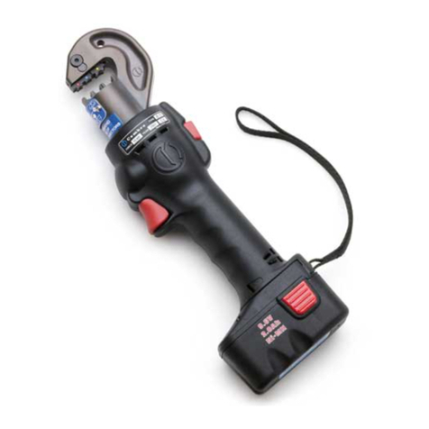
Cembre HT120 User manual

ENGLISH
FRANÇAIS
DEUTSCH
ESPAÑOL
ITALIANO
7. RETURN TO
Cembre
FOR OVERHAUL
In the case of a breakdown contact our Area Agent who will advise you on the problem
andgiveyouthenecessaryinstructionsonhowtodispatchthetooltoournearest service
Centre; if possible, attach a copy of the Test Certificate supplied by
Cembre
together
with the tool or, if no other references are available, indicate the approximate purchase
date and the tool serial number.
7. ENVOI EN REVISION A
Cembre
En cas de dysfonctionnement de l'appareil, merci de vous adresser à notre Agent Ré-
gional qui vous conseillera et le cas échéant vous donnera les instructions nécessaires
pour envoyer l'outil à notre Centre de Service le plus proche. Dans ce cas, joindre une
copie du Certificat d'Essai livré par
Cembre
avec l'outil ou, à défaut d'autres éléments
de référence, indiquer la date d'achat approximative et numéro de série.
7. EINSCHICKEN AN
Cembre
ZUR ÜBERPRÜFUNG
Sollten am Gerät Fehler auftauchen, wenden Sie sich bitte an unsere Gebietsvertretung,
welche Sie gerne beraten und Ihnen alle nötigen Informationen zum Einschicken des
Gerätes an unseren Hauptsitz geben wird. Wenn vorhanden, legen Sie bitte dem Gerät
das von
Cembre
mitgelieferte Überprüfungszertifikat bei; In Ermangelung dieser Infor-
mationen geben Sie bitte an, wann Sie das Gerät erworben haben.
7. DEVOLUCION A
Cembre
PARA REVISIONES
Encaso de fallo de laherramienta, contactar con nuestro Agente de Zona quienles acon-
sejaráyeventualmentelesfacilitarálasinstruccionesnecesariaspararemitirlaherramienta
a nuestro centro de servicio más cercano. En tal caso, adjuntar a ser posible una copia
delCertificadodeEnsayoentregado en su día por
Cembre
conlaherramienta o a falta de
otro elemento de referencia indicar la fecha de compra aproximada y el número de serie.
7. RESA ALLA
Cembre
PER REVISIONE
In caso di guasto contattare il nostro Agente di Zona il quale vi consiglierà in merito e
forniràleistruzioninecessarieperl’inviodell'utensileallanostraSede;sepossibile,allegare
copia del Certificato di Collaudo a suo tempo fornito dalla
Cembre
con l'utensile oppure,
in mancanza di altri riferimenti, indicare la data approssimativa di acquisto.
OPERATION AND MAINTENANCE MANUAL
NOTICE D'UTILISATION ET ENTRETIEN
BEDIENUNGSANLEITUNG
MANUAL DE USO Y MANTENIMIENTO
MANUALE D'USO E MANUTENZIONE
HYDRAULIC CRIMPING TOOL
PRESSE HYDRAULIQUE
HYDRAULISCHES PRESSWERKZEUG
HERRAMIENTA HIDRAULICA DE COMPRESION
UTENSILE OLEODINAMICO DA COMPRESSIONE
HT120
HT120-KV
Cembre Ltd.
Dunton Park
Kingsbury Road, Curdworth - Sutton Coldfield
West Midlands B76 9EB (Great Britain)
Tel.: 01675 470440 - Fax: 01675 470220
E-mail: [email protected]
www.cembre.co.uk
Cembre S.p.A.
Via Serenissima, 9
25135 Brescia (Italia)
Telefono: 030 36921
Telefax: 030 3365766
E-mail: [email protected]
www.cembre.it
Cembre S.a.r.l.
22 Avenue Ferdinand de Lesseps
91420 Morangis (France)
Tél.: 01 60 49 11 90 - Fax: 01 60 49 29 10
B.P. 37 - 91421 Morangis Cédex
E-mail: [email protected]
www.cembre.fr
Cembre España S.L.
Calle Verano, 6 y 8 - P.I. Las Monjas
28850 Torrejón de Ardoz - Madrid (España)
Teléfono: 91 4852580
Telefax: 91 4852581
E-mail: [email protected]
www.cembre.es
Cembre AS
Fossnes Senter
N-3160 Stokke (Norway)
Phone: (47) 33361765
Telefax: (47) 33361766
E-mail: [email protected]
www.cembre.no
Cembre GmbH
Heidemannstraße 166
80939 München (Deutschland)
Telefon: 089/3580676
Telefax: 089/35806777
E-mail: [email protected]
www.cembre.de
Cembre Inc.
Raritan Center Business Park
181 Fieldcrest Avenue
Edison, New Jersey 08837 (USA)
Tel.: (732) 225-7415 - Fax: (732) 225-7414
E-mail: [email protected]
www.cembreinc.com
www.cembre.com
cod. 6261044
11 M 117
Certified Environmental
Management System Certified Occupational
Health & Safety
Management System
Certified Quality
Management System

1
- Tool type
- Outil type
- Handwerkzeug Typ
- Herramienta tipo
- Tipo di utensile
- Year
- Année
- Jahr
- Año
- Anno
WARNING LABELS - ETIQUETTES SIGNALETIQUES - WARNSCHILDER -
ETIQUETAS DE ATENCION - ETICHETTE D'AVVERTENZA
– Before using the tool, carefully read the instructions in this manual.
– Avant d'utiliser cet outil, lire attentivement les instructions de cette notice.
– Vor Inbetriebnahme unbedingt die Bedienungsanleitung durchlesen.
– Antes de utilizar la herramienta, leer atentamente las instrucciones contenidas en esto manual.
– Prima di utilizzare l'utensile, leggere attentamente le istruzioni contenute in questo manuale.
– When operating the tool keep hands away from the danger zone.
– Au cours du sertissage, tenir les mains éloignées de la zone de danger.
– Während des Verpressens nicht mit den Händen in den Pressbereich langen.
– Durante su utilización, mantenga las manos fuera de la zona de peligro.
– Durante l'utilizzo, mantenere le mani fuori dalla zona di pericolo.
2
– Do not pump when dies are not in place.
– Insérer les matrices avant d'actionner l'outil.
– Nicht ohne Einsatzpaar betatigen.
– No poner en presión sin matrices.
– Non mandare in pressione l'utensile senza le matrici inserite.
3
4
TYPE
FORCE
120 kN
HT120
Made in Italy
2 3
123
123
1
4
- Force
- Force
- Kraft
- Fuerza
- Forza
01
38
40
39
44
11
10
12
09
06
05
68
67
04
60
59
14
15
16
18
17
36
35
19
21
20
23
22
26
25
24
28
27
29
03
02
46
45
47
49
53
50
52
13
55
56
54
57
65
64
66
62
61
07
41
51
58
63
30
48
37
08
43
42
34
33
32
31
70
69
130
This manual is the property of
Cembre
:
any reproduction is forbidden without written permission.
Ce manuel est la proprieté de
Cembre
:
toute reproduction est interdite sauf autorisation écrite.
Der Firma
Cembre
bleibt das Eigentumsrecht der Bedienungsanleitung vorbehalten.
Ohne vorherige schriftliche Genehmigung darf die Bedienungsanleitung weder vollständig noch teilweise vervielfältigt werden.
Este manual es propiedad de
Cembre
.
Toda reproducción está prohibida sin autorización escrita.
Questo manuale è di proprietà della
Cembre
:
ogni riproduzione é vietata se non autorizzata per scritto.
FIG. 6 LONGITUDINAL SECTION
COUPE LONGITUDINALE
SCHNITTZEICHNUNG
SECCION LONGITUDINAL
SEZIONE LONGITUDINALE
➠
➠
TG 0356
HT120
Serial number
Numéro de série
Seriennummer
Número de serie
Numero di matricola

FIG. 4 TOOL POSITION FOR MAINTENANCE OPERATIONS
POSITION DE L'OUTIL POUR L'ENTRETIEN
WERKZEUG WARTUNGSPOSITION
COLOCACION PARA LAS OPERACIONES DE MANTENIMIENTO
POSIZIONAMENTO PER LE OPERAZIONI DI MANUTENZIONE
ENGLISH
03
04
02
21
22
66
54
57
29 2
FIG. 5 STORAGE CASE
RANGEMENT
LAGERUNG
ALMACENAMIENTO
CUSTODIA
– CERTAIN KV VERSIONS OF
Cembre
TOOLS ARE PROVIDED WITH ADDITIONAL
COATINGS TO PROTECT THE OPERATOR AND TOOL AGAINST ACCIDENTAL BRUSH
CONTACT WITH ENERGISED CONDUCTORS.
– PROPER TRAINING TECHNIQUES AND PRACTICES SHOULD ALWAYS BE ADHERED TO
WHEN WORKING AROUND ENERGISED CONDUCTORS.
– ALWAYS CONSULT YOUR COMPANY'SWORK RULES AND METHODS TO SELECT
SUITABLE TOOLING,RUBBER INSULATED GLOVES,SHROUDING AND OTHER PROTEC -
TIVE EQUIPMENT.
– UNDER NO CIRCUMSTANCES SHOULD OPERATIVES RELY SOLELY ON THE INSULATING
PROPERTIES OF THE TOOLS ALONE WHEN WORKING AROUND ENERGISED CONDUC-
TORS.
–
PRIOR TO USE PLEASE ENSURE THE TOOL AND SPECIFICALLY THE INSULATING
PROTECTION HAVE NOT BE DAMAGED.
IMPORTANT INFORMATION FOR WORKING IN THE
PROXIMITY OF ENERGISED CONDUCTORS
HYDRAULIC CRIMPING TOOL
HT120 ; HT120-KV
1. GENERAL CHARACTERISTICS
HT120-KV
is suitable for compression of electrical connectors
on conductors up to 400 mm2(800 MCM)
120 (13.5)
700 (10,000)
the tool has two forward speeds of the ram and
automatically switches from a fast advancing
speed of dies to a slower crimping speed.
the tool is provided with max pressure valve; MPC1
special manometer, is available upon request to
check the correct setting of the valve.
Application range:
Crimping force kN (sh ton):
Rated operating pressure bar (psi):
Dimensions
LxW
mm (inches):
Weight kg (lbs):
Recommended oil:
Operating speed:
Safety:
TOOL TYPE:
HT120
AGIP ARNICA 32 or
SHELL TELLUS TX 32
or equivalent.
AGIP ITE360 or
ESSO TRANSFORMER P60
or equivalent.
488x138 (19.21 x 5.43) 492 x 138 (19.37 x 5.43)
5,7 (12.6) 5,8 (12.8)

2. INSTRUCTIONS FOR USE (Ref. to Figs. 1 and 2)
2.1) Setting
With the tool is in the rest position operate as follows:
– Select the appropriate die set for the connector.
– Insertthe die (91) inthe upper seat ofthe tool head untilit is locked bydie/head pin (25).
To ease the die insertion, keep die/head release pin (27) depressed.
– Insert the die (90) in the seat on the head of main ram (22) until it is locked by die/ram
retainer pin (33). To ease this operation, keep die/ram release pin (31) depressed.
– Insert the conductor in the connector.
– Position the connector between the dies and ensure the correct location of the crimp.
2.2) Die advancement
– Operatemoveablehandle(54)forlowerdieadvancement.Thisfirststagerapidlycloses
the dies to the connector.
Do not build up pressure without dies.
Makesurethatdiesareexactlypositionedondesiredcrimppoint,otherwisere-open
dies following instructions as per § 2.4 and position the connector again.
2.3) Crimping
– Continue operating the moveable handle (54). The tool will automatically change over
to the high pressure stage. The ram will advance until the dies meet.
– It is recommended to continue pumping until the maximum pressure valve is activated
and a "click" is heard.
2.4) Dies re-opening (See to Figs. 1 and 3)
Engage the trigger (57) and close the handles completely: in this way the ram will retract
thereby opening the dies.
2.5) Rest setting
– Retract thoroughly the ram, operating as per § 2.4.
– Store the tool in the case.
3. DIE REPLACEMENT (Ref. to Fig. 2)
To replace dies operate as follows:
– Upper die (91)
Take the die off its guide by pushing the die/head release pin (27).
Insert replacement die until secured by the die retaining pin (25).
ENGLISH
1
3
2
FIG. 3 OIL PRESSURE RELEASE PROCEDURE
SCHEMA DU DISPOSITIF DE LIBERATION DE LA PRESSION DE L’HUILE.
SCHEMA DER VORRICHTUNG FÜR ÖLDRUCKABLASS
ESQUEMA DISPOSITIVO DE LIBERACIÓN PRESIÓN DEL ACEITE.
SCHEMA DISPOSITIVO RILASCIO PRESSIONE OLIO
3 - With trigger engaged close moveable handle
- Fermer la poignée mobile en maintenant la
détente baissée
- Den beweglichen Griff schließen, indem der
Drücker in unterer Position gehalten wird.
- Cerrar el mango móvil manteniendo siempre
bajado el gatillo
- Chiudere il manico mobile, tenendo sempre
abbassato il grilletto
2 - Openthemoveablehandle,engagethetrigger
- Ouvrir le bras mobile, baisser la détente
- Den Pumparm öffnen und den Drücker senken
- Abrir el mango móvil, bajar el gatillo
- Aprire il manico mobile, abbassare il grilletto
1 - Rest position
- Repère de repos
- Ruhestellungsposition
- Posición de reposo
- Posizione di riposo
328

02
54
57
66
25
33
FIG. 1 OVERALL VIEW
VUE D'ENSEMBLE
GLOBALANSICHT
VISTA DEL CONJUNTO
VISTA D'ASSIEME
4. WARNING
The tool is robust and requires very little daily maintenance.
Compliance with the following points, should help to maintain the optimum performance
of the tool.
4.1) Accurate cleaning
Dust, sand and dirt are a danger for any hydraulic device.
Every day, after use, the tool must be cleaned with a clean cloth, taking care to remove
any residual, especially close to pivots and moveable parts.
4.2) Storage (Ref. to Fig. 5)
When not in use, the tool should be stored and transported in the plastic case, to prevent
damage.
Plastic case: type VAL P3; dimensions 620x380x135 mm; weight 2,5 kg.
ENGLISH
FIG. 2 DIE REPLACEMENT
27
30
22
27 4
22
90
91
25
30
31
33
27
~ 3 ÷ 4 mm
–Lower die (90)
Take the die off its guide by pushing the die/ram release pin (31).
To facilitate this operation an advancement of 3÷4 mm of the ram (22) is suggested.
Insert the new die in its guide until secured by the die/ram retaining pin (33).

6360112 ▲ ★ 38 GUARNIZIONE OR 1
6900054 39 VITE M 4x6 2
6700500 ▲ 40 ANELLO ELASTICO 1
6362010 ★ 41 GUARNIZIONE R6 1
6560420 42 PERNO MANICO MOBILE 1
6700100 ★ 43 ANELLO ELASTICO ø 7 2
6620382 44 PISTONE POMPANTE 1
6520591 ✚45 MOLLA 1
6760173 ✚46 SPINA KERPIN ø 3x28 1
6362020 ★47 GUARNIZIONE JF 1
6760325 ✚48 SPINA KERPIN ø 5x30 1
6580023 ✚ 49 PIASTRINA DI SCARICO 1
6360240 ★50 GUARNIZIONE OR 1
6641140 ★ 51 ANELLO BK-R6 1
6520861 52 MOLLASBLOCCOPRESSIONE 1
6072010 ✚53 ASTA DI COLLEGAMENTO 1
6480262 ✚54 MANICO MOBILE 1
6760021 ✚55 SPINA KERPIN ø 3x8 1
6760089 ✚56 SPINA KERPIN ø 3x14 1
6370061 ✚57 GRILLETTO 1
6895050 58 VALVOLA COMPLETA 1
6340540 59 GRANO M 10x8 1
6740080 ★ 60 SFERA 5/16" 1
6520260 61 MOLLA SCARICO 1
6600100 62 NOTTOLINO SPINGI SFERA 1
6040060 ★ 63 ANELLO BK 1
6360120 ★ 64 GUARNIZIONE OR 1
6080080 65
BUSSOLAPIST.RITORNOPRESS.
1
6620344 66 PIST.SBLOCCA PRESSIONE 1
6740120 ★ 67 SFERA 7/32" 1
6360160 ★ 68 GUARNIZIONE OR 1
6650118 69 RIVETTO ø 2,5x3,5 2
6232028 70 TARGHETTA (TG. 0128) 1
6620570 ▲ PISTONE MONTATO
6370235 ■ GANCIO “C” MONTATO
6480195 ✚ MANICO MOBILE MONTATO
6000023 ★ CONFEZIONE RICAMBIO
N° Codice N° Codice Part. DENOMINAZIONE Q.tà
4.3) Head rotation
For ease of operation, the tool head can rotate through 180°.
Warning: do not attempt to turn the head if the hydraulic circuit is pressurised.
5. MAINTENANCE (Ref. to Fig. 4 and 6)
Airinthehydrauliccircuitmayaffecttheperformanceofthetool;e.g.nolowerdieadvance-
ment, slow advancement of the lower die; lower die pulsating.
In this case proceed as follows:
5.1) To purge air bubbles from hydraulic circuit
a – Hold tool upright in a vice with handles open (Fig. 4).
b– Unscrew the main handle (02) to expose oil reservoir (04).
c – Remove reservoir cap (03).
d– Operate three or four times the moveable handle (54), to advance the ram (22).
e – Depress pressure release pin (66) until ram is fully retracted.
f – Repeat points (d - e) at least five times, to ensure all air bubbles in the hydraulic circuit
are purged into the reservoir.
g– If the oil level is low, top up as directed in § 5.2.
h– Remove all air from reservoir and fit cap (03).
i– Assemble main handle (02).
If the tool continues to malfunction return the tool for service/repair as detailed in § 7.
5.2) Oil top up
Every six months check the oil level in the reservoir. If necessary, top up the oil level to
the top lip of the reservoir and remove all air from the reservoir, see 5.1, points a, b, c,
e, g, hand i.
Always use clean recommended oil, see § 1.
Do not use old or recycled oil.
Do not use hydraulic brake fluid.
Ensure that disposal of used oil is in accordance with current legislation.
6. LISTA DEI COMPONENTI HT120 (Rif. a Fig. 6)
I particolari indicati con (★) sono quelli che
la
Cembre
consiglia di cambiare sempre
nel caso di un eventuale smontaggio del-
l'utensile.
Dettiparticolarisonofornibilisurichiestanella
“Confezione Ricambio per HT120“.
Per ordinare parti di ricambio, specificare sempre
i seguenti punti:
- numero di codice del componente
- denominazione del componente
- tipo dell'utensile
- numero di matricola dell'utensile
ITALIANOENGLISH
La garanzia decade qualora vengano utilizzate parti di ricambio non originali
Cembre
.
526
Part. DENOMINAZIONE Q.tà
6800072 01 TAPPO MANICO FISSO 1
6480049 02 MANICO FISSO 1
6800040 03 TAPPO SERBATOIO 1
6720120 04 SERBATOIO 1
6635011 05 PUNTALE SCARICO PRES. 1
6360260 ★ 06 GUARNIZIONE OR 1
6900621 07 VITE ASPIRAZIONE COMPL. 1
6232006 08 ETICHETTA (TG 0356) 1
6360160 ★ 09 GUARNIZIONE OR 1
6340720 10 GRANO SCARICOPRESSIONE 1
6740060 ★ 11 SFERA 3/16" 2
6520760 ★ 12 MOLLA ASPIRAZIONE 2
6170182 13 COPERTURA IN GOMMA 1
6740140 ★ 14 SFERA 9/32" 2
6520180 ★ 15 MOLLA ANTIRITORNO 2
6340566 16 GRANO TENUTA SFERA 2
6120700 ▲ 17 COPERCHIO PER MOLLA 1
6300080 ▲ 18 FUNGO 1
6520592 ▲ 19
MOLLAINTERNARICH.PISTONE
1
6520593 ▲ 20
MOLLAESTERNARICH. PISTONE
1
6160032 21 CORPO 1
6620066 ▲ 22 PISTONE 1
6900221 23 VITE M 5x12 1
6100035 24 CHIAVETTA 1
6620440 ■ 25 PIST.FERMA MATR./TESTA 1
6760160 ■ 26 SPINA ELASTICA ø 3x28 1
6620460 ■ 27 PIST.SBLOCCA MATR./TESTA 1
6522006 ■ 28 MOLLA PISTONCINO 1
6340540 ■ 29 GRANO M 10x8 1
6370260 ■ 30 GANCIO "C" 1
6620445 ▲ 31 PIST.SBLOCCA MATR./PIST. 1
6760040 ▲ 32 SPINA ELASTICA ø 3x8 1
6620320 ▲ 33
PIST.FERMA MATR./PISTONE
1
6522006 ▲ 34 MOLLA PISTONCINO 1
6362030 ▲ ★ 35 GUARNIZIONE PIENA 1
6760003 ▲ 36 SPINA ELASTICA ø 2,5x6 1
6040050 ▲ ★ 37 ANELLO BK 1
6. HT120 PARTS LIST (Ref. to Fig. 6)
The guarantee is void if parts used are not
Cembre
original spares.
4.3) Rotazione della testa
La testa dell’utensile può ruotare di 180° rispetto al corpo, permettendo così all’operatore
di eseguire il lavoro nella posizione più agevole.
Attenzione:nonforzarelatestatentandodiruotarlaquandol’utensileéinpressione.
5. MANUTENZIONE (Rif. a Fig. 4 e 6)
Bolle d'aria dell'olio possono causare un funzionamento non corretto dell'utensile.
Tale situazione si manifesta con un comportamento anomalo dell’utensile: pompando, il
pistone non avanza oppure si muove molto lentamente oppure pulsa.
In questo caso bisogna agire nel modo seguente:
5.1) Per espellere le bolle d’aria
a – Capovolgere l'utensile e bloccarlo in una morsa in posizione verticale (ved. Fig. 4) con
il manico mobile (54) divaricato.
b– Svitare dal corpo (21) il manico fisso (02) e toglierlo mettendo in vista il serbatoio in
gomma (04) dell’olio.
c – Estrarre il tappo (03) del serbatoio dell’olio.
d– Azionare tre o quattro volte il manico mobile, facendo avanzare il pistone (22).
e – Rilasciarelapressionedell’oliocomprimendo,conuncacciaviteodaltroattrezzosimile,
il pistoncino di sblocco pressione (66) fino a che il pistone non sia arretrato completa-
mente ed in modo che l’olio sia ritornato tutto nel serbatoio.
f – Ripeterele operazioni(d -e)almeno5volte inmodochele bolled’aria,eventualmente
presenti nel circuito oleodinamico, vengano espulse e si raccolgano nel serbatoio
dell’olio.
g– Prima di richiudere il serbatoio si deve eliminare completamente l’aria.
Se il livello dell’olio fosse basso, effettuare un rabbocco come indicato al punto 5.2.
h– Inserire il tappo (03).
i – Rimontare il manico fisso (02).
Nel caso eccezionale che l’utensile, anche dopo queste operazioni di manutenzione, non
funzionasse correttamente (il pistone non avanza o pulsa) é consigliabile rimandarlo al
più vicino Agente
Cembre
per la sua completa revisione (vedi § 7).
5.2) Rabbocco dell'olio
Il serbatoio dell'olio deve essere sempre pieno; ciò eviterà che si formino bolle d'aria al
suo interno.
Consigliamo di verificare il livello dell'olio almeno ogni 6 mesi; se il livello fosse basso,
procedere al rabbocco eseguendo le operazioni descritte precedentemente in a, b, ced
e, quindi riempire raso il serbatoio.
Completare con le operazioni hed i.
Usare esclusivamente un tipo d’olio consigliato al § 1.
Mai usare olio rigenerato o usato.
E' necessario che l'olio sia pulito.
In occasione di eventuali sostituzioni dell'olio, smaltire l'olio esausto attenen-
dosi scrupolosamente alla legislazione specifica in materia.
ENGLISHITALIANO
When ordering spare parts always
specify the following:
- code number of item
- name of item
- type of tool
- tool serial number
The items marked (★) are those
Cembre
recommendreplacing if thetool is disassem-
bled.Theseitems are supplied on request in
the “HT120 Spare Parts Package”
6800072 01 MAIN HANDLE PLUG 1
6480049 02 MAIN HANDLE 1
6800040 03 RESERVOIR CAP 1
6720120 04 OIL RESERVOIR 1
6635011 05 PRESSURE RELEASE PIN 1
6360260 ★ 06 O-RING 1
6900621 07 SUCTION SCREW 1
6232006 08 LABEL (TG 0356) 1
6360160 ★ 09 O-RING 1
6340720 10
PRESSURE RELEASE DOWEL
1
6740060 ★ 11 3/16" BALL 2
6520760 ★ 12 SUCTION SPRING 2
6170182 13 RUBBER COVER 1
6740140 ★ 14 9/32" BALL 2
6520180 ★ 15 NON RETURN SPRING 2
6340566 16 BALL POSITIONING DOWEL 2
6120700 ▲ 17 SPRING COVER 1
6300080 ▲ 18 RAM SPRING GUIDE 1
6520592 ▲ 19
RAM RETURN INNER SPRING
1
6520593 ▲ 20
RAM RETURN OUTER SPRING
1
6160032 21 BODY 1
6620066 ▲ 22 RAM 1
6900221 23 M 5x12 SCREW 1
6100035 24 KEY 1
6620440 ■ 25 DIE HEAD RETAINER PIN 1
6760160 ■ 26 ø 3x28 SPLIT PIN 1
6620460 ■ 27
DIE HEAD RELEASE PIN 1
6522006 ■ 28 SPRING 1
6340540 ■ 29 M 10x8 DOWEL 1
6370260 ■ 30 "C" HEAD 1
6620445 ▲ 31 DIE RAM RELEASE PIN 1
6760040 ▲ 32 ø 3x8 SPLIT PIN 1
6620320 ▲ 33 DIE RAM RETAINER PIN
1
6522006 ▲ 34 SPRING 1
6362030 ▲ ★ 35 SEAL 1
6760003 ▲ 36 ø 2,5x6 SPLIT PIN 1
6040050 ▲ ★ 37 BACK-UP RING 1
Code N°
25 6
Item QtyDESCRIPTION Code N° Item QtyDESCRIPTION
6360112 ▲ ★ 38 O-RING 1
6900054 39 M 4x6 SCREW 2
6700500 ▲ 40 CIRCLIP 1
6362010 ★ 41 SEAL 1
6560420 42 MOVEABLE HANDLE PIVOT 1
6700100 ★ 43 ø7 CIRCLIP 2
6620382 44 PUMPING RAM 1
6520591 ✚45 SPRING 1
6760173 ✚46 ø 3x28 DRIVE PIN 1
6362020 ★47 SEAL 1
6760325 ✚48 ø 5x30 DRIVE PIN 1
6580023 ✚49 RELEASE PLATE 1
6360240 ★50 O-RING 1
6641140 ★ 51 BACK-UP RING 1
6520861 52
PRESSURE RELEASE SPRING
1
6072010 ✚53 PUSH ROD 1
6480262 ✚54 MOVEABLE HANDLE 1
6760021 ✚55 ø 3x8 DRIVE PIN 1
6760089 ✚56 ø 3x14 DRIVE PIN 1
6370061 ✚57 TRIGGER 1
6895050 58 MAX PRESSURE VALVE 1
6340540 59 M 10x8 DOWEL 1
6740080 ★ 60 5/16" BALL 1
6520260 61 SPRING 1
6600100 62 BALL SUPPORT 1
6040060 ★ 63 BACK-UP RING 1
6360120 ★ 64 O-RING 1
6080080 65
PRESSURERELEASERAM BUSH
1
6620344 66 PRESSURE RELEASE PIN 1
6740120 ★ 67 7/32" BALL 1
6360160 ★ 68 O-RING 1
6650118 69 RIVET ø 2,5x3,5 2
6232028 70 METAL LABEL (TG. 0128) 1
6620570 ▲ COMPLETE RAM
6370235 ■ COMPLETE “C” HEAD
6480195 ✚
COMPLETEMOVEABLEHANDLE
6000023 ★ SPARE PARTS PACKAGE

4. AVVERTENZE
L’utensile é robusto e non richiede attenzioni particolari; per ottenere un corretto funzio-
namento basterà osservare alcune semplici precauzioni:
4.1) Accurata pulizia
Tenere presente che la polvere, la sabbia e lo sporco rappresentano un pericolo per ogni
apparecchiatura oleodinamica. Dopo ogni giorno d’uso si deve ripulire l’utensile con uno
straccio pulito, avendo cura di eliminare lo sporco depositatosi su di esso, specialmente
vicino alle parti mobili.
4.2) Custodia (Rif. a Fig. 5)
Per proteggere l'utensile da urti accidentali e dalla polvere, quando non viene utilizzato, é
bene custodirlo nell'apposita valigetta in materiale plastico accuratamente chiusa.
Detta valigetta (tipo VAL P3) ha dimensioni (620x380xh135) mm e pesa 2,5 kg.
ITALIANOFRANÇAIS
FIG. 2 INSERIMENTO MATRICI
724
PRESSE HYDRAULIQUE
TYPE HT120 ; HT120-KV
– L‘OUTILS
Cembre
DE LA VERSION KV SONT EQUIPES D'UN REVETEMENT SU-
PLEMENTAIREAFINDE PROTEGER L'UTILISATEUR CONTRE TOUTCONTACT ACCIDENTEL
AVEC UN CABLE SOUS TENSION.
– LES TECHNIQUES APPROPRIEES ET LES REGLES DE SECURITE DOIVENT TOUJOURS
ETRE STRICTEMENT APPLIQUEES LORS D'UNE OPERATION SOUS TENSION.
– CONSULTER SYSTEMATIQUEMENT LES PROCEDURES DE TRAVAIL DE VOTRE SOCIETE
AFIN DE CHOISIR L'OUTILLAGE APPROPRIE, GANTS ISOLES OU TOUT AUTRES MATE-
RIELS DE PROTECTIONS.
– LES UTILISATEURS NE DOIVENT EN AUCUN CAS COMPTER UNIQUEMENT SUR LES
PROPRIETES ISOLANTES DE L'OUTIL LORSQU'ILS TRAVAILLENT PRES DES CONDUC-
TEURS SOUS TENSION.
– AVANT CHAQUE UTILISATION ASSUREZ-VOUS QUE L'ISOLANT DE L'OUTIL N'EST PAS
ENDOMMAGE.
INFORMATIONS IMPORTANTES POUR L'UTILISATION
A PROXIMITE DE CABLES SOUS TENSION
HT120-KV
conçue pour le sertissage des connecteurs électriques
pour câbles jusqu' à 400 mm2(800 MCM)
120 (13.5)
700 (10,000)
l’outil passe automatiquement
de la vitesse rapide d’approche des matrices,
à la vitesse lente de montée en pression.
l'outil est pourvu d'une valve de surpression. Pour vérifier
le bon fonctionnement de cette valve, un manomêtre
spécial, notre réf. MPC1, est disponible à la demande.
Domaine d'application:
Force de sertissage kN (sh ton):
Pression nominale bar (psi):
Dimensions
LxL
mm (inches):
Poids kg (lbs):
Huile recommandée:
Avance rapide:
Sécurité:
OUTIL TYPE:
HT120
AGIP ARNICA 32 ou
SHELL TELLUS TX 32
ou équivalents
AGIP ITE360 ou
ESSO TRANSFORMER P60
ou équivalents
488 x 138 (19.21 x 5.43) 492 x 138 (19.37 x 5.43)
5,7 (12.6) 5,8 (12.8)
1. CARACTERISTIQUES GENERALES
–Matrice inferiore (90)
Sfilare la matrice dalle sue guide tenendo premuto il pistoncino sblocca matrice/pistone
(31) in modo da annullare l’azione di ritenuta del pistoncino ferma matrice/pistone (33).
Si consiglia di far avanzare di 3÷4 mm il pistone (22) per facilitare l’operazione.
Inserirelanuovamatricenellesueguidesinoalbloccaggiocolpistoncinofermamatrice/
pistone.
22
90
91
25
30
31
33
27
~ 3 ÷ 4 mm

2. INSTRUCTIONS D'UTILISATION (Voir Fig. 1 et 2)
2.1) Mise en service
Avec l'outil en position de repos procéder comme suit:
– Prendre les matrices à utiliser selon le type de sertissage à effectuer.
– Insérerlapartie(91)de lamatricedans songuidesupérieurdanslatetede l'outiljusqu'à
son verrouillage par l'axe de verrouillage matrice/tête (25).
– Insérer la partie (90) de la matrice dans sa guide dans la tête du piston principal (22)
jusqu'à son verrouillage par l'axe de verrouillage matrice/piston (33).
– Insérer le conducteur dans le connecteur.
– Positionnercedernierentrelesdeuxmatricesenalignantlazoneàsertiravecl'empreinte
des matrices mêmes.
2.2) Avance des matrices
– En actionnant le bras mobile (54) le piston (22) amène rapidement les deux matrices
au contact du connecteur à sertir.
Insérer les matrices avant d'utiliser l'outil.
S'assurerquelesmatricessontbienpositionnéessurlazoneàsertir,sinondesserrer
les matrices en suivant les instructions du § 2.4 et repositionner le connecteur.
2.3) Sertissage
– Poursuivre la manæuvre du bras mobile.
On passera automatiquement de la vitesse rapide à la lente; le piston montera prgres-
sivement jusqu'au contact des matrices.
– Il est conseillé de continuer à pomper jusqu'à l'intervention de la valve de surpression
(on doit entendre un léger "clic").
2.4) Réouverture des matrices (Voir Fig. 1 et 3)
– En maintenant la détente (57) pressée, fermer à fond le bras mobile, ce qui provoquera
la retour du piston et par conséquent la fermeture des matrices.
2.5) Rangement
– Faire descendre complétement le piston en suivant les indications du § 2.4.
– Ranger l'outil dans son coffret.
3. CHANGEMENT DES MATRICES (Voir Fig. 2)
Pour changer les matrices, procéder comme suit:
–Matrice supérieure (91)
Retirer la matrice en poussant l'axé de déblocage matrice/tête (25).
Insérer la nouvelle matrice.
2. ISTRUZIONI PER L’USO (Rif. a Fig. 1 e 2)
2.1) Preparazione
Con l’utensile in posizione di riposo operare come segue:
– Scegliere la coppia di matrici adatta alla connessione da effettuare.
– Inserire una delle matrici (91) nelle guide superiori della testa dell’utensile fino al suo
bloccaggiocolpistoncinofermamatrice/testa(25).Perfacilitarel’inserzionedellamatrice
tenere premuto il pistoncino sblocca matrice/testa (27).
– Inserirel’altramatrice(90)nelleguidericavatesullatestadelpistoneprincipale (22) fino
al suo bloccaggio col pistoncino ferma matrice/pistone (33). Per facilitare l’inserzione
della matrice tenere premuto il pistoncino sblocca matrice/pistone (31).
– Infilare il conduttore nel connettore.
– Posizionare quest'ultimo fra le due matrici allineando la zona da comprimere con l’im-
pronta delle matrici stesse.
2.2) Accostamento delle matrici
– Azionare il manico mobile; il pistone (22) avanzerà velocemente portando le matrici in
contatto con il connettore.
Mai mettere in pressione l’utensile senza le matrici inserite nelle sedi della
testa.
Assicurarsi che le matrici si trovino esattamente in corrispondenza con la zona
da comprimere; in caso contrario riaprirle seguendo le istruzioni del punto 2.4 e
riposizionare il connettore.
2.3) Compressione
– Continuare ad azionare il manico mobile.
Si passerà automaticamente dall’alta alla bassa velocità; il pistone avanzerà progres-
sivamente fino a portare le matrici in battuta tra loro.
– Consigliamocomunquedipomparefinoall'interventodellavalvoladimassimapressione
della quale si avvertirà lo scatto.
2.4) Sblocco delle matrici (Rif. a Fig. 1 e 3)
– Tenendo premuto il grilletto (57) chiudere i manici a fondo; si otterrà così il ritorno del
pistone con conseguente apertura delle matrici.
2.5) Messa a riposo
– Far arretrare completamente il pistone agendo come visto al punto 2.4.
– Riporre l'utensile nella sua valigetta.
3. CAMBIO DELLE MATRICI (Rif. a Fig. 2)
Per effettuare il cambio delle matrici operare come segue:
–Matrice superiore (91)
Sfilare la matrice dalle sue guide tenendo premuto il pistoncino sblocca matrice/testa
(27) in modo da annullare l’azione di ritenuta del pistoncino ferma matrice/testa (25).
Inserire la nuova matrice nelle sue guide fino al bloccaggio col pistoncino ferma matri-
ce/testa.
FRANÇAIS
ITALIANO
23 8

4. PRECAUTIONS
Cet outil est robuste et ne nécessite aucune préoccupation ou entretien particulier.
Les recommandations qui suivent sont néanmoins souhaitables pour assurer une longé-
vité optimum:
4.1) Nettoyage élémentaire
Veiller à protéger l'outil de la poussière, du sable et de la boue qui sont un danger à tout
système hydraulique. Chaque jour après utilisation, l'outil doit être nettoyé à l'aide d'un
chiffon propre, tout particulièrement aux endroits de pièces mobiles.
4.2) Rangement (Voir Fig. 5)
Il est de bonne règle de remettre l'outil dans son coffret, fermé, après usage, en protection
des chocs et de la poussière.
Ce coffret (type VAL P3) a comme dimensions (620x380x135) mm et un poids de 2,5 kg.
UTENSILE OLEODINAMICO DA COMPRESSIONE
TIPO HT120 ; HT120-KV
ITALIANOFRANÇAIS
FIG. 2 INSERTION DES MATRICES
922
– LEVERSIONI KVDEGLI UTENSILI
Cembre
SONO PROVVISTE DI UN RIVESTIMENTO
AGGIUNTIVOPER PROTEGGERE L'OPERATOREEL'UTENSILEDAACCIDENTALI CONTATTI
CON CONDUTTORI IN TENSIONE.
– QUALORA SI DOVESSE LAVORARE IN PRESENZA DI CAVI IN TENSIONE BISOGNERÀ
PRIMA SOTTOPORSI AD UN'ADEGUATO ADDESTRAMENTO TECNICO EPRATICO.
– DOVRANNO SEMPRE ESSERE SEGUITE LE REGOLE ELE MODALITÀ PREVISTE DALLA
VOSTRA AZIENDA PER LA SCELTA DI ATTREZZATURA ADEGUATA, DI GUANTI ISOLATI
IN GOMMA, MASCHERE ED ALTRI DISPOSITIVI DI PROTEZIONE.
– INNESSUNCASO,L'OPERATOREDOVRÀ AFFIDARSI ESCLUSIVAMENTEALLEPROPRIETÀ
ISOLANTIDEGLI UTENSILI,QUALORA SI TROVI ALAVORARE NELL'AREADI CONDUTTORI
IN TENSIONE.
– PRIMA DELL'UTILIZZO ÉNECESSARIO ACCERTARSI SEMPRE CHE L'UTENSILE ELA
SUA PROTEZIONE ISOLANTE NON SIANO DANNEGGIATI.
INFORMAZIONI IMPORTANTI PER L'UTILIZZO IN
PROSSIMITÁ DI CONDUTTORI IN TENSIONE
HT120-KV
adatto all'installazione di connettori elettrici a compres-
sione per conduttori in genere fino a 400 mm2(800 MCM)
120 (13.5)
700 (10,000)
sono due: una rapida di avvicinamento delle matrici
ed una più lenta di compressione.
La commutazione da una all'altra velocità é automatica.
l’utensile è munito di valvola di massima pressione
la cui corretta taratura è verificabile mediante
l’apposito strumento MPC1 fornibile a richiesta.
Campo di applicazione:
Forza sviluppata kN (sh ton):
Pressione nom.di eserciziobar (psi):
Dimensioni
LxL
mm (inches):
Peso kg (lbs):
Olio consigliato:
Velocità di avanzamento:
Sicurezza:
UTENSILE TIPO:
HT120
AGIP ARNICA 32 oppure
SHELL TELLUS TX 32
o equivalenti.
AGIP ITE360 oppure
ESSO TRANSFORMER P60
o equivalenti.
488 x 138 (19.21 x 5.43) 492 x 138 (19.37 x 5.43)
5,7 (12.6) 5,8 (12.8)
1. CARATTERISTICHE GENERALI
22
90
91
25
30
31
33
27
~ 3 ÷ 4 mm
–Matrice inférieure (90)
Retirer la matrice en poussant l'axe de déblocage matrice/piston (31).
Insérerlanouvellematricedanssesguidesjusqu'àsonblocageparl'axedeverrouillage
matrice/tête (33).
Cette opération est facilitée par l'avancement de 3-4 mm du piston (22).

6. LISTA DE COMPONENTES HT120 (Ref. a Fig. 6)
Al pedir piezas de repuesto, indicar siempre los
elementos siguientes:
- número de código del elemento
- descripción del elemento
- tipo de herramienta
- número de serie de la herramienta
4.3) Rotation de la tête
La tête de l'outil pivote de 180° par rapport au corps, permettant à l'utilisateur de travailler
dans la meilleure position.
Attention: ne pas forcer la rotation de la tête, lorsque le circuit hydraulique est
sous pression.
5. ENTRETIEN (Voir Fig. 4 et 6)
Le seul problème pouvant être rencontré parfois, nécessitant une intervention, est la
présence d'une bulle d'air dans le circuit hydraulique.
Cet incident est caractérisé par un mauvais fonctionnement de l'outil: dans l'action de
montée en pression, soit la matrice inférieure ne monte pas, soit elle progresse trés len-
tement, soit elle monte et redescent pulsativement.
Dans ce cas, il est nécessaire de procéder comme suit:
5.1) Elimination de bulles d'air
a – Mettre l'outil en position verticale dans un étau (Fig. 4) en écartant le bras mobile (54).
b– Oter complètement le bras principal (02) laissant apparaître le réservoir d'huile en
caoutchouc (04).
c – Retirer le capuchon (03) du réservoir.
d– Actionner 3 ou 4 fois le bras mobile (54), faisant avancer le piston (22).
e – Relâcher la pression d'huile, en compressant l'axe (66) jusqu'à la rétraction totale du
piston et de l'huile dans son réservoir.
f – Refaire les opérations (d -e) au moins 5 fois, afin de permettre aux éventuelles bulles
d'air contenues dans le circuit hydraulique d'être rejetées et évacuées par le réservoir
d'huile.
g– Avantde refermerle réservoir d'huile,l'air doit êtrecomplètement évacué. Sile niveau
d'huile est bas, un complément doit être fait comme mentionné au § 5.2.
h– Refermer le capuchon (03).
i –Remonter le bras principal (02).
Dansl'éventuelcasoù,malgrécetteintervention,l'outilnefonctionneraitpascorrectement,
(soit la matrice inférieure ne monte pas, soit elle monte et rédescent pulsativement) il est
recommandé de le retourner à
Cembre
pour une révision complète (voir § 7).
5.2) Complément d'huile
La présence de bulles d'air est évitée en maintenant le réservoir d'huile toujours plein.
Par conséquent nous préconisons de vérifier tous les 6 mois, que le réservoir soit plein, et
dans la négative, de le compléter. Pour ce faire, reportez vous aux descriptions ci dessus:
a,b, c, d et e, puis emplir complètement le réservoir.
Après cela, terminer les opérations h et i.
Utiliser exclusivement un type d'huile mentionné au § 1.
Ne jamais utiliser d'huile usagée ou recyclée.
Il est indispensable que l'huile soit neuve.
Encasdechangementd'huile,l'huileusagéedoit êtreéliminée conformément
aux normes en vigueur.
FRANÇAIS
ESPAÑOL
La garantía pierde eficacia si se utilizan piezas de repuesto distintas de las originales
Cembre
.
Loselementosindicadoscon(★)sonaquellos
que
Cembre
aconsejacambiarenelcasode
un posible desmontaje de la herramienta.
Estos elementos se suministran bajo pedido
en el “Paquete de Repuesto para HT120“.
21 10
Elemento
DESCRIPCION C.dad
N° Código Elemento
DESCRIPCION C.dad
N° Código Elemento
DESCRIPCION C.dad
N° Código
6800072 01 TAPON MANGO FIJO 1
6480049 02 MANGO FIJO 1
6800040 03 TAPON DEPOSITO ACEITE 1
6720120 04 DEPOSITO DE ACEITE 1
6635011 05
CONTERADEDESCARGA DE PRES.
1
6360260 ★ 06 JUNTA DE GOMA 1
6900621 07 VALVULA DE SUCCION 1
6232006 08 ETIQUETA (TG 0356) 1
6360160 ★ 09 JUNTA DE GOMA OR 1
6340720 10
TORNILLODEDESCARGA DE PRES.
1
6740060 ★ 11 BOLA 3/16" 2
6520760 ★ 12 MUELLE DE SUCCION 2
6170182 13 COBERTURA DE GOMA 1
6740140 ★ 14 BOLA 9/32" 2
6520180 ★ 15 MUELLE ANTI-RETORNO 2
6340566 16 TORNILLO RETEN DE BOLA 2
6120700 ▲ 17 TAPA MUELLE 1
6300080 ▲ 18 SOPORTE PISTON 1
6520592 ▲ 19
MUELLEINT.RETORNO PISTON
1
6520593 ▲ 20
MUELLEEXT.RETORNO PISTON
1
6160032 21 CUERPO 1
6620066 ▲ 22 PISTON 1
6900221 23 TORNILLO M 5x12 1
6100035 24 TOPE 1
6620440 ■ 25
PERNOBLOQUEOMATRIZ/CABEZA
1
6760160 ■ 26 PASADOR ø 3x28 1
6620460 ■ 27
PERNODESBLOQ.MATRIZ/CABEZA
1
6522006 ■ 28 MUELLE 1
6340540 ■ 29 TORNILLO M 10x8 1
6370260 ■ 30 CABEZA "C" 1
6620445 ▲ 31
PERNODESBLOQ.MATRIZ/PISTON
1
6760040 ▲ 32 PASADOR ø 3x8 1
6620320 ▲ 33
PERNOBLOQUEOMATRIZ/PISTON
1
6522006 ▲ 34 MUELLE 1
6362030 ▲ ★ 35 JUNTA DE GOMA 1
6760003 ▲ 36 PASADOR ø 2,5x6 1
6040050 ▲ ★ 37 ANILLA DE PLASTICO 1
6360112 ▲ ★ 38 JUNTA DE GOMA OR 1
6900054 39 TORNILLO M 4x6 2
6700500 ▲ 40 ANILLA ELASTICA 1
6362010 ★ 41 JUNTA DE GOMA R6 1
6560420 42 PASADOR MANGO MOVIL 1
6700100 ★ 43 ANILLA ELASTICA ø 7 2
6620382 44 PISTON BOMBEO 1
6520591 ✚45 MUELLE 1
6760173 ✚46 PASADOR ø 3x28 1
6362020 ★47 JUNTA DE GOMA JF 1
6760325 ✚48 PASADOR ø 5x30 1
6580023 ✚49 PLACA 1
6360240 ★ 50 JUNTA DE GOMA OR 1
6641140 ★ 51 ANILLA DE PLASTICO 1
6520861 52 MUELLE 1
6072010 ✚ 53 ASTA DE COLIGAMIENTO 1
6480262 ✚54 MANGO MOVIL 1
6760021 ✚55 PASADOR ø 3x8 1
6760089 ✚56 PASADOR ø 3x14 1
6370061 ✚ 57 GATILLO 1
6895050 58 VALVULA COMPLETA 1
6340540 59 TORNILLO M 10x8 1
6740080 ★ 60 BOLA 5/16" 1
6520260 61
MUELLEDEDESCARGA DE PRESION
1
6600100 62
PISTONDESBLOQUEODE PRESION
1
6040060 ★ 63 ANILLA DE PLASTICO 1
6360120 ★ 64 JUNTA DE GOMA OR 1
6080080 65
C
ONTACTO PISTON RETOR.DEPRES
.
1
6620344 66 SOPORTE BOLA 1
6740120 ★ 67 BOLA 7/32" 1
6360160 ★ 68 JUNTA DE GOMA OR 1
6650118 69 PASADOR ø 2,5x3,5 2
6232028 70 TARJETA (TG. 0128) 1
6620570 ▲ PISTON COMPLETO
6370235 ■ CABEZA "C" COMPLETA
6480195 ✚ MANGO MOVIL COMPLETO
6000023 ★ PAQUETE DE REPUESTO

4.3) Rotación de la cabeza
La cabeza de la herramienta puede rotar hasta 180° respecto al cuerpo, permitiendo al
operario realizar el trabajo en la posición más adecuata.
Atención: no fuerce la cabeza, intentando rotarla, mientras el circuito hidráulico
esté presurizado.
5. MANTENIMIENTO (Ref. a Figg. 4 y 6)
Las burbujas de aire en el circuito del aceite pueden causar un funcionamiento incorrecto
de la herramienta. Tal situación se manifesta con un funcionamiento anormal de la herra-
mienta: al bombear, el pistón no avanza, o bien se mueve muy lentamente ó vibra.
En este caso se debe de obrar del modo siguiente:
5.1) Para expulsar las burbujas de aire
a – Pongalaherramientaabajoysujetelaconunamordazaenposiciónvertical(verFig.4)
con el mango móvil (54) separado.
b– Desviecompletamentteelmangofijo(02)dalcuerpo(21)dejandoalavistaeldepósito
de aceite (04).
c – Extraer el tapón (03) del depósito de aceite.
d– Accione 3 ò 4 veces el mango movil, haciendo avanzar el pistón (22).
e – Libere la presión del aceite, pulsando con un destornillador o similar el pistoncillo de
liberacion de la presión (66) hasta que el pistón principal no haya retrocedido com-
pletamente, de modo que el aceite sea devuelto al depósito.
f – Repita las operaciones (d -e) al menos 5 veces, a fin de que las burbujas de aire del
circuito hidráulico sean expulsadas y se extraigan del deposito del aceite.
g– Antes de volver a cerrar el depósito se debe eliminar el aire.
Si el nivel de aceite fuese bajo, efectue su rellenado como se indica en el epig. 5.2.
h– Vuelva a enroscar el tapón (03).
i –Coloque el mango fijo (02) .
Encasodequelaherramienta,inclusodespuésdeestaoperacionesdemantenimiento,no
funcionasecorrectamente(elpistón noavanzao vibra)esaconsejable llevarlaa
Cembre
para su revisión completa (ver Epig. 7).
5.2) Rellenado de aceite
El depósito del aceite debe estar siempre lleno; lo cual evitará que se formen burbujas
de aire en su interior.
Se aconseja verificar el nivel de aceite, al menos cada 6 meses, si el nivel fuese bajo,
proceda al rellenado, realizando las operaciones descritas anteriormente, en los puntos
a, b, cy e, por ultimo rellene hasta el borde del depósito.
Complete con las operaciones hy i.
Use exclusivamente uno de los tipos de aceite recomendados en el Epig. 1.
No use nunca aceite usado.
Debe ser aceite limpio.
En casodeuneventualcambiodeaceite,depositeelaceiteusado,respetando
escrupulosamente la legislación especifica respecto a la materia.
6. PIECES DETACHEES HT120 (Voir Fig. 6)
Les éléments accompagnés d'un (★) sont
ceuxque
Cembre
recommandederempla-
cer en cas de démontage de l'outil.
Cesélémentssontfournissurdemandedans
le “Paquet Rechange pour HT120”.
Lorsdelacommandedepiècesdétachées,veuillez
indiquer toujours les éléments suivants:
- numéro de code article de la pièce
- désignation de la pièce
- type d'outil
- numéro de série de l'outil
ESPAÑOLFRANÇAIS
La garantie perd tout effet en cas d'emploi de pièces détachées différentes des pièces
d'origine
Cembre
.
N° Code
11 20
Q.té
DENOMINATIONPièce
6800072 01 CAPUCHON 1
6480049 02 BRAS PRINCIPAL 1
6800040 03 CAPUCHON DE RESERVOIR 1
6720120 04 RESERVOIR 1
6635011 05 SOMMET DECOMPRESSION 1
6360260 ★ 06 JOINT TORIQUE 1
6900621 07 VIS ASPIRATION 1
6232006 08 ETIQUETTE (TG 0356) 1
6360160 ★ 09 JOINT TORIQUE OR 1
6340720 10 GOUPILLE DE DECOMPRESS. 1
6740060 ★ 11 BILLE 3/16" 2
6520760 ★ 12 RESSORT ASPIRATION 2
6170182 13
COUVERTUREDE CAOUTCHOUC
1
6740140 ★ 14 BILLE 9/32" 2
6520180 ★ 15 RESSORT ANTI-RETOUR 2
6340566 16 AXE 2
6120700 ▲ 17 COUVERCLE RESSORT 1
6300080 ▲ 18 COUSSINET 1
6520592 ▲ 19
RESSORTINTER.RAPPEL PISTON
1
6520593 ▲ 20
RESSORTEXTER.RAPPEL PISTON
1
6160032 21 CORPS 1
6620066 ▲ 22 PISTON 1
6900221 23 VIS M 5x12 1
6100035 24 CLAVETTE 1
6620440 ■ 25
AXEDEVERROUILLAGE MATR./TETE
1
6760160 ■ 26 FICHE ø 3x28 1
6620460 ■ 27
AXEDEDEBLOQUAGE MATR./TETE
1
6522006 ■ 28 RESSORT 1
6340540 ■ 29 VIS SANS TETE M 10x8 1
6370260 ■ 30 CHAPE EN "C" 1
6620445 ▲ 31
AXEDEDEBLOQ. MATR./PISTON
1
6760040 ▲ 32 FICHE ø 3x8 1
6620320 ▲ 33
AXEDEVERROUILL. MATR./PISTON
1
6522006 ▲ 34 RESSORT 1
6362030 ▲ ★ 35 JOINT TORIQUE 1
6760003 ▲ 36 FICHE ø 2,5x6 1
6040050 ▲ ★ 37 ANNEAU BK 1
N° Code Q.té
DENOMINATIONPièce
6360112 ▲ ★ 38 JOINT TORIQUE OR 1
6900054 39 VIS M 4x6 2
6700500 ▲ 40 ANNEAU ELASTIQUE 1
6362010 ★ 41 JOINT TORIQUE R6 1
6560420 42 AXE BRAS MOBILE 1
6700100 ★ 43 ANNEAU ELASTIQUE ø 7 2
6620382 44 PISTON 1
6520591 ✚45 RESSORT 1
6760173 ✚ 46 FICHE KERPIN ø 3x28 1
6362020 ★47 JOINT TORIQUE JF 1
6760325 ✚48 FICHE KERPIN ø 5x30 1
6580023 ✚49 PLATINE 1
6360240 ★50 JOINT TORIQUE OR 1
6641140 ★ 51 ANNEAU BK-R6 1
6520861 52 RESSORT 1
6072010 ✚53 RALLONGE DE JONCTION 1
6480262 ✚54 BRAS MOBILE 1
6760021 ✚55 FICHE KERPIN ø 3x8 1
6760089 ✚56 FICHE KERPIN ø 3x14 1
6370061 ✚57 DETENTE 1
6895050 58 VALVE COMPLETE 1
6340540 59 VIS SANS TETE M 10x8 1
6740080 ★ 60 BILLE 5/16" 1
6520260 61 RESSORT 1
6600100 62 CLIQUET PORTE BILLE 1
6040060 ★ 63 ANNEAU BK 1
6360120 ★ 64 JOINT TORIQUE OR 1
6080080 65
ANNEAUAXEDE RETOUR PRESSION
1
6620344 66 AXE DE DECOMPRESSION 1
6740120 ★ 67 BILLE 7/32" 1
6360160 ★ 68 JOINT TORIQUE OR 1
6650118 69 RIVET ø 2,5x3,5 2
6232028 70 PLAQUETTE (TG. 0128) 1
6620570 ▲ PISTON COMPLET
6370235 ■ CHAPE EN "C" COMPLETE
6480195 ✚ BRAS MOBILE COMPLET
6000023 ★ PAQUET RECHANGE

HYDRAULISCHES PRESSWERKZEUG
TYP HT120 ; HT120-KV
4. ADVERTENCIAS
Esta herramienta es robusta y no requiere cuidados especiales para obtener un funcio-
namiento correcto, bastará observar algunas precauciones sencillas:
4.1) Limpieza adecuada
Tenga presente que el polvo, la arena y la suciedad en general, representan un peligro
para toda herramienta hidráulica. Tras cada día de uso, se debe limpiar la herramienta
con un trapo limpio, teniendo cuidado de eliminar la suciedad depositada, especialmente
junto a las partes móviles.
4.2) Almacenamiento (Ref. a Fig. 5)
Paraproteger la herramienta degolpesaccidentalesydelpolvo cuando no sevaautilizar,
es conveniente guardarla en su estuche de plástico de cierre hermético.
Dicho estuche (mod. VAL P3) de dimensiones 620x380x135mm y pesa 2,5 kg.
DEUTSCHESPAÑOL
FIG. 2 INSERCION DE LAS MATRICES
19 12
– EINIGE ISOLIERTE
Cembre
-
WERKZEUGE SIND MIT ZUSÄTZLICHEN SCHTZMASS-
NAHMEN VERSEHEN, UM DEN MONTEUR UND DAS WERKZEUG GEGEN UNGEWOLL
TES BERÜHREN VON UNTER SPANNUNG STEHENDEN LEITERN ZU SCHÜTZEN.
– IMMER MIT DEM VERANTWORTLICHEN ENTSCHEIDEN, WELCHES DIE RICHTIGEN
W
ERKZEUGE SIND, SOWIE DIE ARBEITSMETHODE BESPRECHEN UND WELCHE
S
ICHERHEITSMASSNAHMEN VORGENOMMEN WERDEN SOLLEN Z.B. GUMMI-
HANDSCHUHE, ISOLIERTE ABDECKUNGEN UND ANDERE SCHUTZAUSRÜSTUNGEN.
– DIE ANLAGE MUSS STÄNDIG BEOBACHTET WERDEN, WENN AN UNTER SPANNUNG
STEHENDEN LEITERN GEARBEITET WIRD.
D
ERMONTEUR DARF SICH NICHT NURAUF DEN ISOLATIONSSCHUTZ DE WERKZEUGES
VERLASSEN.
– DAS WERKZEUG IST VOR DEM EINSATZ AUF BESCHÄDIGUNGEN ZU KONTROLLIEREN.
DABEI IST AUF DEN ISOLIERSCHUTZ ZU ACHTEN.
WICHTIGE HINWEISE BEI TÄTIGKEITEN IN DER NÄHE
VON UNTER SPANNUNG STEHENDEN TEILEN
HT120-KV
Geeignet zum Verpressen von Verbindern
und Kabelschuhen bis zu einem Querschnitt
von max. 400 mm2 (800MCM).
120 (13.5)
700 (10,000)
Das Werkzeug ist mit einer Doppelkolbenhydraulik au-
sgerüstet, die anfangs ein schnelles Zusammenfahren
der Presseinsätze ermöglicht. Dann wird automatisch
auf den langsameren Arbeitshub umgeschaltet.
Das Werkzeug ist mit einem Überdruckventil ausg
stattet. Der Arbeitsdruck kann mit dem Meßgerät
MPC1, das auf Anfrage lieferbar ist, gemessen
werden.
Anwendungsbereich:
Preßkraft kN (sh ton):
Arbeitsdruck bar (psi):
Abmessungen
LxB
mm (inches):
Gewicht kg (lbs):
Empfohlenes Öl:
Kolbenvorschub:
Sicherheit:
WERKZEUG TYP:
HT120
AGIP ARNICA 32
oder
SHELL TELLUS TX 32
oder ähnliches.
AGIP ITE360
oder
ESSO TRANSFORMER P60
oder ähnliches.
488 x 138 (19.21 x 5.43) 492 x 138 (19.37 x 5.43)
5,7 (12.6) 5,8 (12.8)
1. ALLGEMEINE EIGENSCHAFTEN
– Matriz inferior (90)
Desencajelamatrizdesusguías,manteniendopresionadoelpistoncillodesbloqueador
de matrices/pistón (31), con el fin de anular la accion de retencion del pistoncillo fija-
matrices/pistón (33).
Es aconsejable avanzar de 3÷4 mm el pistón (22) para facilitar la operacion.
Inserte la nueva matriz en sus guías, hasta su bloqueo con el pistoncillo fija matrices/
pistón (33).
22
90
91
25
30
31
33
27
~ 3 ÷ 4 mm

2. INSTRUCCIONES DE USO (Ref. a Figg. 1 y 2)
2.1) Preparación
Con la herramienta en posición de reposo opere como sigue:
– Seleccione la matriz adecuada para la conexión a efectuar.
– Inserteunadelasmatrices(91)enelhueco-guíasuperior,delacabezadelaherramienta,
hasta su bloqueo con el pistoncillo fija-matriz/cabeza (25).
Parafacilitar la insercion de la matriz, mantenga presionadoel pistoncillo desblqueador
de matrices/cabeza (27).
– Inserte la otra matriz (90) en la guía, localizada sobre la cabeza del piston principal (22)
hastasu bloqueo con elpistoncillo fija-matrices/pistón (33).Parafacilitar la insercionde
la matriz, mantenga presionado el pistoncillo desbloqueador-matrices/pistón (22).
– Introduca el conductor en el conector.
– Coloque este ultimo entre las dos matrices, alineando la zona a comprimir con la marca
de las matrices.
2.2) Aproximación de las matrices
– Accioneselmangomóvil(54),elpistón(22)avanzarárápidamente,poniendolasmatrices
en contacto con el conector.
No presione nunca la herramienta sin las matrices insertas enl su lugar, en
la cabeza
Asegúresedequelasmatricesseencuentranexactamenteencorrespondenciaconla
zona a comprimir; en caso contrario, vuélvala a abrir, siguiendo las instrucciones
del punto 2.4 y vuelva a colocar el conector.
2.3) Compresión
– Continue accionando el mango móvil (54).
Se pasará automáticamente de la alta a la baja velocidad; el pistón avanzará progresi-
vamente hasta colocar las matrices sobre el conector.
– Aconsejamos, en todo caso, bombear hasta la intervencion de la válvula de seguridad,
por la que se advertirá el disparo.
2.4) Desbloqueo de las matrices (Ver Figg. 1 y 3)
–Manteniendo apretado el gatillo (57), cerrar a fondo los mangos.
Se provoca así el retorno del pistón con la consiguiente abertura de las matrices.
2.5) Puesta en reposo
– Haga retroceder, completamente, el pistón actuando como en el epígrafe 2.4.
– Vuelva a colocar la herramienta en su estuche.
3. CAMBIO DE LAS MATRICES (Ref. a Fig. 2)
Para efectuar el cambio de las matrices, actúe como sigue:
–Matriz superior (91)
Desencaje la matriz de sus guías, manteniendo presionado el pistoncillo desbloquea-
matrices/cabeza (27), con el fin de anular la accion de retencion del pistoncillo fija-ma
trices/cabeza (25).
Inserte la nueva matriz en sus guías, hasta el bloqueo con el pistoncillo fija-matrices/
cabeza (25).
2. BEDIENUNGSHINWEISE (Siehe Bild 1 und 2)
2.1) Vorbereitung
Wenn das Werkzeug in Ruhestellung ist, sind folgende Schritte notwending:
– Passenden Presseinsatz auswählen.
– Druckknopf (32) zum Einsetzen des oberen Presseinsatzes auf der Vorderseite des
Presskopfesdrücken,dasichdamitderArretierungsstift(34)anhebtundderPresseinsatz
seitlich herausgeschoben werden kann.
Beim Einsetzen des Presseinsatzes drückt sich der Arretierungsstift (34) selbsttätig in
die vorgesehene Nut am Presseinsatz.
– Druckknopf (38) zum Einsctzen des unteren Presseinsatzes auf der Vorderseite des
Presskopfesdrücken,dasichdamitderArretierungsstift(39)anhebtundderPresseinsatz
seitlich herausgeschoben werden kann.
– Bei dieser Tätigkeit ist es von Vorteil, wenn der Kolben (28) 3–4 mm vorgefahren ist.
– Beim Einsetzen des Presseinsatzes drückt sich der Arretierungsstift (33) selbsttätig in
die vorgesehene Nut am Presseinsatz.
– Den zu verpressenden Leiter in den Verbinder oder Kabelschuh einlegen.
– PositionierenSieden Verbinderoder Kabelschuhandervorgeschriebenen Position am
Presseinsatz.
2.2) Positionierung
– Den Pumparm betätigen; der Kolben (22) wird im Schnelllauf etwas vorgefahren und
die Presseinsätze werden sich auf der Verbinder oder Kabelschuh anpassen.
Niemals das Werkzeug ohne Presseinsätze betätigen.
DiePresseinsätzemüssenindiegewünschtePositionamVerbinderoderKabelschuh
gebrachtwerden. Sollte diese nicht korrekt sein, muss dasWerkzeugentsprechend
Punkt 2.4 geöffnet werden und es kann neu positioniert werden.
2.3) Verpressung
– Pumparm (54) betätigen, der Kolben fährt schnell vor Sobald der Druckaufbau erfolgt,
schaltetdas Werkzeug automatisch um,die Presseinsätze fahrenlangsam zusammen.
– Bei Erreichen des maximalen Druckes schaltet das Überdruckventil automatisch ab,
welches durch ein "Klick" akustisch zu hören ist.
2.4) Presseinsätze lösen (Siehe Bild 1 und 3)
– Den Drücker (57) gedrückt halten und die Griffe gut schließen: Auf diese Weise findet
der Kolbenrücklauf statt, wobei sich die Presseinsätze öffnen.
2.5) Nachbereitung
– Kolben zurückfahren entspr. Pkt. 2.4
– Werkzeug in die dazugehörige Verpackungseinheit legen.
3. PRESSEINSATZWECHSEL (Siehe Bild 2)
Für den Presseinsatzwechsel folgendermasse vorgehen:
–Oberer Presseinsatz (91)
Druckknopf (27) zum Einsetzen des oberen Presseinsatzes auf der Vorderseite des
Presskopfesdrücken,dasichdamitderArretierungsstift(25)anhebtundderPresseinsat
seitlich herausgeschoben werden kann.
BeimEinsetzendesneuenPresseinsatzesdrücktsichderArretierungsstift(25)selbsttätig
in die vorgesehene Nut am Presseinsatz.
ESPAÑOL
DEUTSCH
13 18

HERRAMIENTA HIDRAULICA DE COMPRESION
TIPO HT120 ; HT120-KV
DEUTSCHESPAÑOL
FIG. 2 EINRASTEN PRESSEINSATZE
4. HINWEISE
Das Werkzeug ist robust und benötigt keine spezielle Pflege oder Instandhaltung.
Zur Erhaltung der Garantieansprüche beachten Sie folgende Hinweise:
4.1) Pflege
Dieses hydraulische Werkzeug sollte vor starker Verschmutzung geschützt werden, da
diese für ein hydraulisches System gefährlich ist. Jeden Tag nach der Arbeit sollte das
Werkzeug mit einem Tuch von Schmutz und Staub gereinigt werden; besonders die
beweglichen Teile.
4.2) Lagerung (Siehe Bild 5)
WenndasWerkzeugnichtbenötigtwird,sollteesinderabschliessbarenKunststoffkassett-
egelagert werden und ist somit gegen Beschädigungen wie Stoss und Staub geschützt.
Die Kunststoffkassette (Typ VAL P3) hat die Abmasse (620x380xh135) mm und ein Ge-
wicht von 2,5 kg.
17 14
– LAS VERSIONES KV, DE LAS HERRAMIENTAS
Cembre
ESTAN PROVISTAS DE UNA
CAPA ADICIONALPARA PROTEGERALOPERARIO YLA HERRAMIENTA DE UN CONTACTO
ACCIDENTAL CON CONDUCTORES CON TENSION.
– CUANDO SE TRABAJA EN PROXIMIDAD DE CONDUCTORES CON TENSION SIEMPRE
DEBE ESTAR PRESENTE UNA FORMACION TECNICA YPRACTICA ADECUADA.
– SIEMPRESEDEBE CONSULTARALACOMPAÑIALASNORMASYMETODOS DE TRABAJO
PARA UTILIZAR LA HERRAMIENTA ADECUADA, GUANTES DE GOMA AISLADOS, ASI
COMO CUALQUIER OTRO EQUIPO DE PROTECCION.
– BAJONINGUNACIRCUNSTANCIA DEBECONFIARSESOLAMENTEEN LAS PROPIEDADES
AISLANTES DE LAS HERRAMIENTAS CUANDO SE TRABAJA EN PROXIMIDAD DE CON-
DUCTORES CON TENSION.
– ANTES DE LA UTILIZACION DEBE ASEGURARSE DE QUE LA HERRAMIENTA YESPE-
CIALMENTE EL AISLAMIENTO NO PRESENTA DAÑOS.
INFORMACION IMPORTANTE PARA TRABAJOS
PRÓXIMOS A CABLES CON TENSIÓN
HT120-KV
idónea para la instalación de conectores eléctricos,
por compresión, para conductores en general hasta
400 mm
2
(800 MCM)
120 (13.5)
700 (10,000)
son dos: una rápida de aproximación de las
matrices y otra más lenta de compresion. El paso
de una a otra velocidad es automático.
la herramienta esta provista de una válvula de
seguridad con la que la compresion correcta es
verificable mediante el instrumento adecuado
MPC1 disponible mediante pedido.
Campo de aplicación:
Fuerza desarrollada kN (sh ton):
Présion nominal de trabajobar (psi):
Dimensiones
LxA
mm (inches):
Peso kg (lbs):
Aceite recomendado:
Velocidad de avance:
Seguridad:
HERRAMIENTA TIPO:
HT120
AGIPARNICA 32 o
SHELL TELLUS TX 32
o equivalentes
AGIP ITE360 o
ESSO TRANSFORMER P60
o equivalentes
488 x 138 (19.21 x 5.43) 492 x 138 (19.37 x 5.43)
5,7 (12.6) 5,8 (12.8)
1. CARACTERíSTICAS GENERALES
–Unterer Presseinsatz (90)
Druckknopf (31) zum Einsetzen des unteren Presseinsatzes auf der Vorderseite des
Presskopfesdrücken,dasichdamitderArretierungsstift(33)anhebtundderPresseinsatz
seitlich herasgeschoben werden kann.
Bei dieser Tätigkeit ist es von Vorteil, wenn der Kolben (22) 3-4 mm vorgefahren ist.
Beim Einsetzen des Presseinsatzes drückt sich der Arretierungsstift (33) selbsttätig in
die vorgesehene Nut am Presseinsatz.
90
91
25
30
31
22
33
27
~ 3 ÷ 4 mm

6. ERSATZTEILLISTE HT120 (Siehe Bild 6)
Geben Sie bitte bei der Bestellung aller Ersa-
tzteile folgende Informationen an:
- Codenummer des Ersatzteils
- Beschreibung des Ersatzteils
- Werkzeug Typ
- Seriennr. des Werkzeugs
Die mit (★) gekennzeichneten Bestandteile
sind jene, welche
Cembre
auszuwechseln
empfiehlt,fallsdasGerätinseineBestandteile
zerlegt wird. Genannte Einzelteile sind auf
Anfrage in der “Ersatzteilpackung HT120"
erhältlich.
4.3) Drehbewegung des Kopfes
Das Werkzeug ist mit einem Kopf ausgerüstet, der um 180° drehbar ist und somit ein
komfortables Arbeiten ermöglicht.
Der Kopf sollte keinesfalls in eine andere Position gedreht werden, während die
Handpresse unter Druck steht.
5. WARTUNG (Siehe Bild 4 und 6)
BefindetsichLuftimHydrauliksystem,kanneszumfehlerhaftenArbeitendesWerkzeuges
kommen.DieseszeigtsichinungewöhnlichemVerhaltendesWerkzeuges:beiPumpbeginn
bewegen sich die unteren Presseinsätze nicht oder nur sehr langsam bzw. stossweise.
Ist dies der Fall, sind die folgenden Hinweise zu beachten:
5.1) Entlüften
a – Werkzeug mit dem Presskopf nach unten (Bild 4) positionieren.
Dabei muss der Pumparm in der Öffnungsstellung sein.
b– Den Handgriff (02) vom Öltank (04) losschrauben und wegziehen.
c – Ölverschlusskappe (03) entfernen.
d– Mit dem Pumparm (54) den Kolben (22) vorfahren.
e – Öldruck wieder ablassen, und der Kolben fährt vollständig zurück.
f – Vorgang(d -e)einigemalewiederholen,sodassdiegesamteLuftausgetretenistoder
sich im Öltank gesammelt hat.
g– BevorderÖltankgeschlossenwird,kannbeiBedarfnochÖlnachgefülltwerdenentspr
Pkt. 5.2.
h– Öltank verschliessen.
i –Handgriff (02) über den Öltank schieben und anziehen.
Sehr selten kann es passieren, dass das Werkzeug nach diesen Wartungsarbeiten nicht
oder nicht richtig funktioniert. In diesem Fall sollte entspr. Pkt. 7 verfahren werden.
5.2) Öl nachfüllen
Luftblasen im Öltank lassen sich vermeiden, wenn der Tank stets gut gefüllt ist.
Deshalb sollte alle 6 Monate der Tank kontrolliert und bei Bedarf aufgefüllt werden.
Dies erfolgt so wie in den Punkten a, b, cund ebeschrieben wurde.
Danach wird der Öltank aufgefüllt.
Zuletzt wird wie in Punkt hund ibeschrieben vorgegangen.
Zum Nachfüllen stets das unter Pkt.1 angegebene Öl benützen.
Niemals mit gebrauchtem oder altem Öl nachfüllen.
Das Öl muss stets sauber sein.
Bei einem Ölwechsel sind unbedingt die vorgeschriebenen Normen zur Ent-
sorgung von Altöl zu beachten.
DEUTSCHDEUTSCH
Die Garantie verfällt, wenn nicht Originalteile aus dem Hause
Cembre
in das Gerät
eingebaut werden.
15 16
BESCHREIBUNG
Menge
Codenr. Teil
6800072 01 HANDGRIFFKAPPE 1
6480049 02 HANDGRIFF 1
6800040 03 ÖLVERSCHLUSSKAPPE 1
6720120 04 ÖLTANK 1
6635011 05 DRUCKABLASSTIFT 1
6360260 ★ 06 O-RING 1
6900621 07 ANSAUGSCHRAUBE 1
6232006 08 AUFKLEBER (TG 0356) 1
6360160 ★ 09 O-RING 1
6340720 10 DRUCKABLASSPASSTIFT 1
6740060 ★ 11 KUGEL 3/16" 2
6520760 ★ 12 ANSAUGFEDER 2
6170182 13 KUNSTSTOFFBEDECKUNG 1
6740140 ★ 14 KUGEL 9/32" 2
6520180 ★ 15 FEDER 2
6340566 16 KUGELHALTER 2
6120700 ▲ 17 FEDERDECKEL 1
6300080 ▲ 18 KOLBENFÜHRUNG 1
6520592 ▲ 19
INNEREKOLBENRÜCKHOLFEDER
1
6520593 ▲ 20
AUSSEREKOLBENRÜCKHOLFEDER
1
6160032 21 GRUNDKÖRPER 1
6620066 ▲ 22 KOLBEN 1
6900221 23 SCHRAUBE M 5x12 1
6100035 24 ABDECKUNG 1
6620440 ■ 25
ARRETIERSTIFTOBEREEINSATZ
1
6760160 ■ 26 FEDERSTIFT ø 3x28 1
6620460 ■ 27 DRUCKKNOPF 1
6522006 ■ 28 FEDER 1
6340540 ■ 29 STIFT M 10x8 1
6370260 ■ 30 C-KOPF 1
6620445 ▲ 31 DRUCKKNOPF 1
6760040 ▲ 32 FEDERSTIFT ø 3x8 1
6620320 ▲ 33
ARRETIERSTIFTUNTEREEINSATZ
1
6522006 ▲ 34 FEDER 1
6362030 ▲ ★ 35 STÜTZRING 1
6760003 ▲ 36 FEDERSTIFT ø 2,5x6 1
6040050 ▲ ★ 37 ABSTREIFRING 1
BESCHREIBUNG
Menge
Codenr. Teil
6360112 ▲ ★ 38 O-RING 1
6900054 39 SCHRAUBE M 4x6 2
6700500 ▲ 40 SPRENGRING 1
6362010 ★ 41 STÜTZRING 1
6560420 42 PUMPARMBOLZEN 1
6700100 ★ 43 SPRENGRING ø 7 2
6620382 44 PUMPKOLBEN 1
6520591 ✚45 FEDER 1
6760173 ✚46 STIFT ø 3x28 1
6362020 ★47 STÜTZRING 1
6760325 ✚48 STIFT ø 5x30 1
6580023 ✚49 PLATTCHEN 1
6360240 ★50 O-RING 1
6641140 ★ 51 ABSTREIFRING 1
6520861 52 DRUCKABLASSFEDER 1
6072010 ✚53 VERBINDUNGSSTIEL 1
6480262 ✚54 PUMPARM 1
6760021 ✚55 STIFT ø 3x8 1
6760089 ✚56 STIFT ø 3x14 1
6370061 ✚57 DRÜCKER 1
6895050 58 ÜBERDRUCKVENTIL 1
6340540 59 STIFT M 10x8 1
6740080 ★ 60 KUGEL 5/16" 1
6520260 61 FEDER 1
6600100 62 KUGELHALTER 1
6040060 ★ 63 ABSTREIFRING 1
6360120 ★ 64 O-RING 1
6080080 65 KOLBENBUCHSE 1
6620344 66 DRUCKABLASSKOLBEN 1
6740120 ★ 67 KUGEL 7/32" 1
6360160 ★ 68 O-RING 1
6650118 69 NIET ø 2,5x3,5 2
6232028 70 TYPENSCHILD (TG. 0128) 1
6620570 ▲ VORMONTIERTE KOLBEN
6370235 ■ VORMONTIERTE C-KOPF
6480195 ✚ VORMONTIERTE PUMPARM
6000023 ★ ERSATZTEILPACKUNG
This manual suits for next models
1
Table of contents
Other Cembre Power Tools manuals

Cembre
Cembre B1300-C-KV User manual

Cembre
Cembre RHU600 User manual

Cembre
Cembre B15 User manual

Cembre
Cembre BTEPE2.DET12 User manual

Cembre
Cembre B1300-UC User manual

Cembre
Cembre RHU 1000 Owner's manual

Cembre
Cembre NR-25B User manual

Cembre
Cembre B-FL750 User manual

Cembre
Cembre B500 User manual

Cembre
Cembre B540ND User manual

Cembre
Cembre BTEPE2.DET10 User manual

Cembre
Cembre B131-UC User manual

Cembre
Cembre B135-UC User manual

Cembre
Cembre B35-50D User manual

Cembre
Cembre PNB-3 Series User manual

Cembre
Cembre B600 User manual

Cembre
Cembre B450ND-BV User manual

Cembre
Cembre HT131-C User manual

Cembre
Cembre MTE1-S User manual

Cembre
Cembre HT120-KV User manual