INSTALLATION
GB
(GB) 2
GB
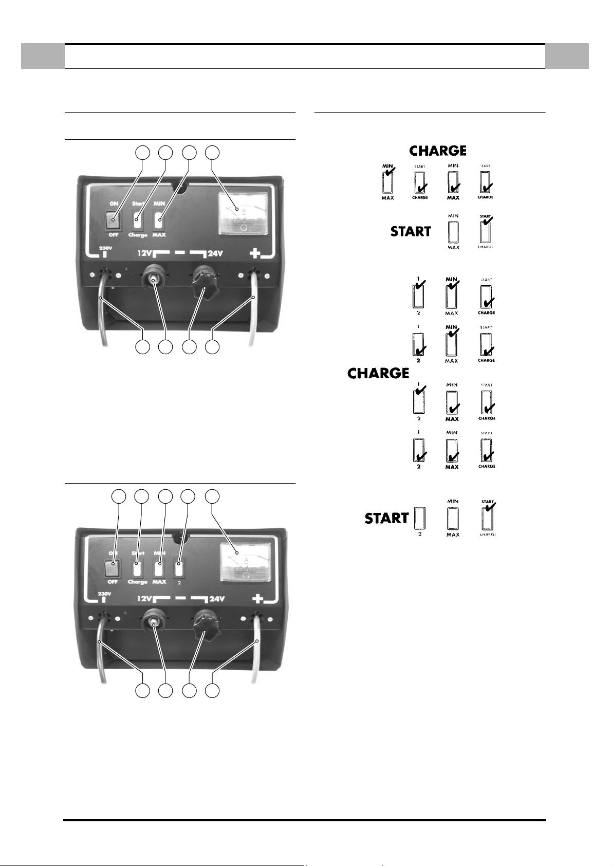
1.0 INSTALLATION
Before installing the battery charger, make sure that:
1. It is protected from humidity and rain.
2. It is installed on a stable, safe surface.
3. There is sufficient space at the back of the charger to ensure good ventila-
tion.
4. The clamps are not short-circuiting.
5. The mains cable and the clamp cables are in perfect condition.
1.1 CONNECTING TO THE MAINS.
Check that the mains voltage corresponds with that indicated on the identification
plate fixed to the battery charger (230 V a.c. or 240 V a.c. 50/60 Hz). For the con-
nection, use a three-pole plug (two phases earth) rated at least 10 Amp.
1.2 CONNECTING TO THE BATTERY (PREPARING FOR THE CHARGE).
Before starting to charge the battery, check that the capacity (Ah) of the battery
concerned is within the maximum and minimum Cr values indicated on the identi-
fication plate of your battery charge
a. Cr max (Ah): maximum battery capacity, chargeable with the maximum
current that can be supplied in 15 hours.
b. Cr min (Ah: minimum battery capacity,chargeable with the minimum cur-
rent that can be supplied in 4 hours.
1. With the mains cable being disconnected, insert the negative cable plug in
the output terminal with the voltage that corresponds with the battery to be
charged (12V or 24V depending on the battery).
2. Connect the battery to the charger: the red cable to the battery’s positive
terminal and the black cable to its negative one. First of all, connect the pos-
itive cable to the battery’s positive terminal (which is not earthed), then con-
nect the negative cable to the car body, well away from the battery and the
fuel lines.
3. Plug the unit into the mains socket.
4. When the battery has been charged, remove the power plug or set the
charger’s power switch to “OFF”. Then remove the conductor from the car
body and the battery; finally, remove the clamps from the battery.
After use, store the battery charger in a dry place.
1.3 SIMULTANEOUSLY CHARGING MORE THAN ONE BATTERY.
If you have to charge more than one battery simultaneously, you can connect
them in series or in parallel. Of the two systems, connection in series is prefera-
ble, as in this way you can check that the current in each battery corresponds to
that indicated by the ammeter.
1.4 PROTECTIONS.
The battery charger is fitted with an overload cut-out that intervenes in the event
of:
1. Over-charging (excessive current supplied to the battery).
2. Short-circuiting of the charging clamps.
3. Inversion of polarity on the battery terminals.
Battery chargers with fuses: replace, if necessary, with an identical fuse having the
same rating.
BEFORE CHANGING THE FUSE, DISCONNECT THE POWER CABLE
FROM THE MAINS. IF THIS WARNING IS IGNORED, CEMONT DECLI-
NES RESPONSIBILITY FOR ANY CONSEQUENCES THAT MAY RESULT.
1.5 USEFUL TIPS.
1. To avoid gas building up, always charge batteries in a well-ventilated area.
2. Before starting charging, take the cap off each element.
3. Check that the level of liquid inside the battery covers the tops of the plates;
if it does not, top-up with distilled water to the maximum level indicated on
the battery.
4. The liquid in the battery is highly corrosive, and must not be allowed to
come into contact with the skin.
5. Clean the positive and negative terminals of any oxide scale, so as to ensure
good contact with the clamps.
6. Never let the two clamps make contact when the battery charger is con-
nected to the mains.
7. If the battery with which you intend to use this battery charger is perma-
nently installed in a vehicle, refer to the “ELECTRICAL SYSTEM” or “MAIN-
TENANCE” section/s of the owner’s handbook and/or maintenance manual.
Before starting charging, it is advisable to disconnect the positive cable of
the vehicle’s electrical system.
8. Check the battery’s voltage before connecting it to the battery charger.
Remember that a 6-Volt battery has three caps and a 12-Volt battery has
six. In some cases, there may be two 12-Volt batteries; if so, you will
require a voltage of 24 Volt to charge both.
9. Check the polarity of the terminals. The positive terminal is marked “+”:
the negative one is marked “-”. If these symbols are indistinguishable,
remember that the negative terminal is the one connected directly to the
vehicle’s body.
2.0 TECHNICAL SPECIFICATIONS
2.1 DATA PLATE
WARNING.
NEVER CONNECT OR DISCONNECT THE CLAMPS FROM THE BATTERY WITH
THE BATTERY CHARGER FUNCTIONING. FIRST SWITCH THE UNIT OFF.
WARNING:
REPLACING THE FUSE WITH ONE HAVING A CURRENT RATING DIFFERENT
FROM THAT INDICATED ON THE IDENTIFICATION PLATE COULD CAUSE
DAMAGE TO PROPERTY OR INJURY TO PERSONS. FOR THE SAME REA-
SON, YOU SHOULD NEVER REPLACE THE FUSE WITH COPPER WIRE OR
OTHER MAKESHIFT MEANS.
200A 300A 400A
Single-phase power supply A 230
Frequency Hz 50/60
Starting/charging voltage V 12 - 24
Effective charging current A 24 32 38
Average charging current
EN 60335–2-29 A202834
Starting current 0 Volt A 200 300 400
Starting current 1.0 Volt/C
EN 60335-2-29 A 180 230 280
Max. power absorbed
charging/starting KW 0,6/6,5 0,9/8 1/8,4
Min. fuse with precharge A 16
Rated reference capacity Ah/15h 265 355 430
Battery startable min./max. Ah 20 20-35 35-50
Battery startable with precharge
min./max. Ah 20-45 45-65 65-100
Dimensions mm 360x670x380
Weight Kg 13 15 15
Fuses 1x80A 2x50A 1x50A +
1x80A