INSTALLATION
F
(F) 2
F
1.0 INSTALLATION
Avant d'installer le chargeur de batteries, s'assurer que:
1. L'appareil soit protégé de l'humidité et de la pluie.
2. L'appareil soit installé sur une surface stable et sûre.
3. L'espace libre à l'arrière de l'appareil soit suffisant pour assurer une bonne
ventilation.
4. Ne pas court-circuiter les pinces.
5. Le câble d'alimentation et les câbles des pinces soient en parfait état.
1.1 RACCORDEMENT AU RÉSEAU.
VERSION 500A et 650A S’assurer que la tension du réseau corresponde à celle
inscrite sur le tableau des caractéristiques sérigraphié sur l’appareil (230 Vac ou
240 Vac 50/60 Hz) et brancher une prise 2 pôle + terre d’au moins 10 A.
VERSION 1250A S’assurer que la tension du réseau corresponde à celle inscrite
sur le tableau des caractéristiques sérigraphié sur l’appareil (400 Vac 50/60 tri-
phasé) et munir le câble d’alimentation d’une prise quadripolaire (3 phases +
terre) ayant une capacité minimale de16 A.
1.2 RACCORDEMENT À LA BATTERIE (PRÉPARATION POUR LA CHARGE).
Avant de procéder à la charge, il est nécessaire de contrôler que la capacité de la
batterie (Ah) à recharger soit comprise entre les valeurs Cr max. et Cr min. inscri-
tes sur l'appareil:
a. Cr max (Ah): capacité de la batterie maximale rechargeable avec le courant
maximal délivré pendant 15 heures.
b. Cr min (Ah): capacité de la batterie minimale rechargeable avec le courant
minimal délivré pendant 4 heures.
1. Le câble d'alimentation étant débranchés, insérer le connecteur du câble
négatif dans la borne de sortie correspondant à la tension de la batterie à
charger (12V si la batterie est de cette tension, ou bien 24V).
2. Raccorder la batterie au chargeur: câble rouge au positif et câble noir au
négatif de la batterie. Raccorder en premier le câble positif à la borne posi-
tive de la batterie, puis ensuite la pince négative au châssis du véhicule, loin
de la batterie et des canalisations de carburant.
3. Brancher la prise d'alimentation au réseau électrique.
4. La charge terminée, débrancher d'abord la prise de courant ou placer
l'interrupteur général sur la position "OFF", et ensuite les pinces de la batte-
rie en enlevant d'abord celle de la borne reliée à la masse.
Ranger ensuite le chargeur dans un endroit sec.
1.3 CHARGE SIMULTANÉE DE PLUSIEURS ACCUMULATEURS.
En cas de charge simultanée de plusieurs batteries, il est possible de brancher
celles-ci en série ou en parallèle. De ces deux méthodes, le branchement en série
est le plus recommandé car dans ce cas le courant de charge qui circule dans
chaque batterie est celui indiqué par l'ampèremètre.
1.4 PROTECTIONS.
Le chargeur de batteries est muni d'une protection qui intervient en cas de:
1. Surcharge (courant de charge excessif).
2. Court-circuit des pinces du chargeur.
3. Inversion de polarité au niveau des bornes de la batterie.
Pour les appareils munis de fusibles, il est obligatoire, en cas de remplacement,
de n'utiliser que des fusibles analogues à ceux d'origine et de même valeur nomi-
nale.
L'OPÉRATION DE REMPLACEMENT DU FUSIBLE DOIT ÊTRE EFFECTUÉE
AVEC LE CÂBLE D'ALIMENTATION DÉBRANCHÉ DU RÉSEAU. DANS LE
CAS CONTRAIRE, LE FABRICANT REFUSE DE PRENDRE EN CHARGE
TOUTE RESPONSABILITÉ AINSI TOUTE ÉVENTUELLE RÉPARATION.
1.5 CONSEILS UTILES.
1. Effectuer la charge dans des locaux aérés pour éviter les accumulations de
gaz.
2. Avant la charge, ouvrir le bouchon de chaque élément.
3. S'assurer que le niveau de l'électrolyte soit suffisant pour recouvrir toutes
les plaques, dans le cas contraire, ajouter de l'eau distillée jusqu'au repère
MAX. indiqué sur la batterie.
4. Ne pas toucher le liquide à l'intérieur de la batterie. Il est corrosif.
5. Nettoyer les bornes positive et négative pour enlever toute trace d'oxydation
de façon à assurer un bon contact des pinces.
6. Éviter absolument de mettre les deux pinces en contact l'une de l'autre lor-
sque l'appareil est relié au réseau électrique.
7. Si la batterie qui doit être rechargée avec cet appareil reste fixée dans le
véhicule, consulter aussi la notice d'utilisation et d'entretien du véhicule aux
paragraphes "INSTALLATION ÉLECTRIQUE" ou "ENTRETIEN".
De préférence, avant de procéder à la charge, débrancher le câble positif fai-
sant partie de l'installation électrique du véhicule.
8. Contrôler la tension de la batterie avant d'y raccorder le chargeur. Se sou-
venir qu'une batterie de 6 volts possède 3 bouchons tandis qu'une batterie
de 12 volts en comporte 6. Dans quelques cas, il peut y avoir 2 batteries de
12 volts. Il faudra alors disposer d'une tension de 24 volts pour charger ces
deux batteries ensemble.
9. Vérifier la polarité des bornes, positif: symbole +, négative: symbole -. Si
ces symboles ne sont pas visibles, se souvenir que la borne négative est
celle directement reliée à la carrosserie.
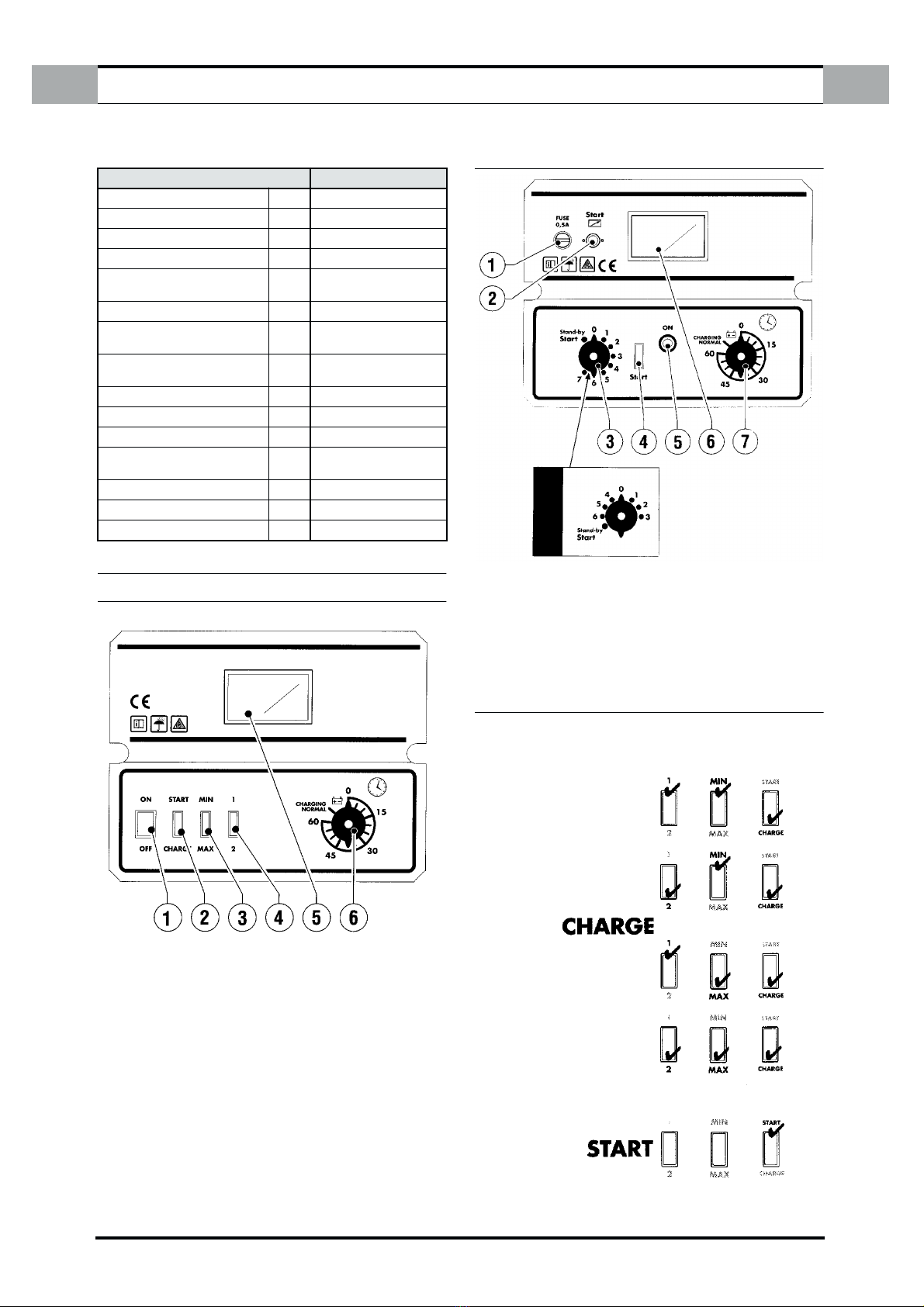
2.0 CARACTÉRISTIQUES TECHNIQUES
2.1 PLAQUE DE DONNEES TECHNIQUES
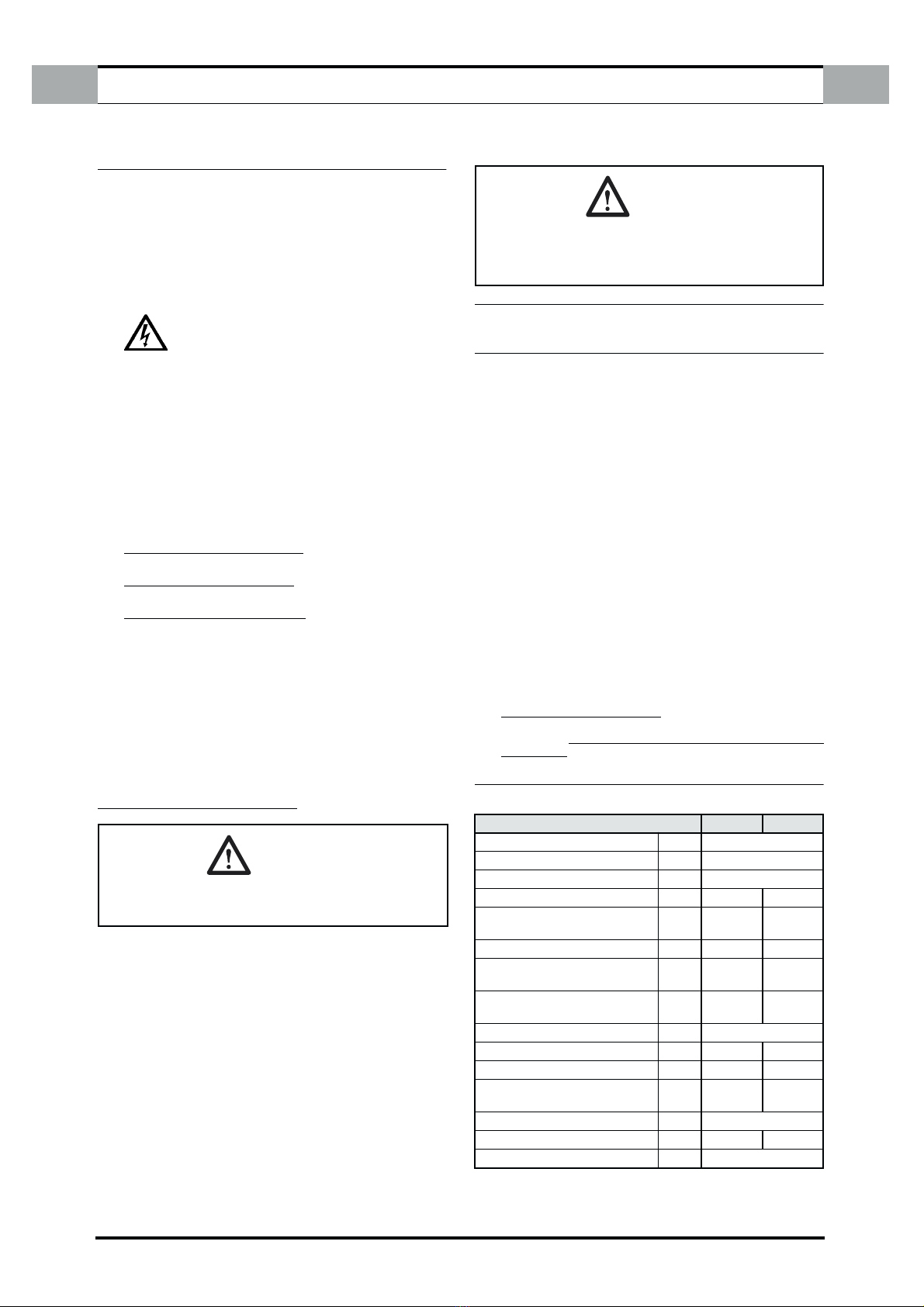
ATTENTION:
NE JAMAIS BRANCHER OU DÉBRANCHER LES PINCES SI LE
CHARGEUR EST EN FONCTIONNEMENT. ÉTEINDRE D'ABORD
L'APPAREIL.
500A 650A
Alimentation monophasée A 230
Fréquence Hz 50/60
Tension de charge/démarrage V 12 - 24
Courant de charge efficace A 45 66
Courant de charge moyen
EN 60335–2-29 A40 60
Courant de démarrage 0 0 Volt A 500/500 650/650
Courant de démarrage 1,0 Volt/C
EN 60335-2-29 A
300/270 400/400
Puissance max. absorbée charge
démarrage KW 1,3/10,2 1,8/15
Fusible minimum avec précharge A 16
Capacité nominale de référence Ah/15h 560 700
Batterie démarrable min./max. Ah 45-65 65-120
Batterie démarrable avec
précharge min./max. Ah 80-150 150-240
Dimensions mm 350 x 750 x 320
Poids Kg 20,7 24,2
Fusibles 2 x 100A
ATTENTION:
REMPLACER LE FUSIBLE PAR UN AUTRE DE VALEUR DIFFÉRENTE
DE CELLE INDIQUÉE SUR L'APPAREIL PEUT PROVOQUER DES
DOMMAGES AUX PERSONNES OU AUX BIENS. POUR LA MÊME
RAISON, IL EST INTERDIT DE FAÇON ABSOLUE DE REMPLACER LE
FUSIBLE PAR UN FIL DE CUIVRE OU TOUT AUTRE MATÉRIAU.