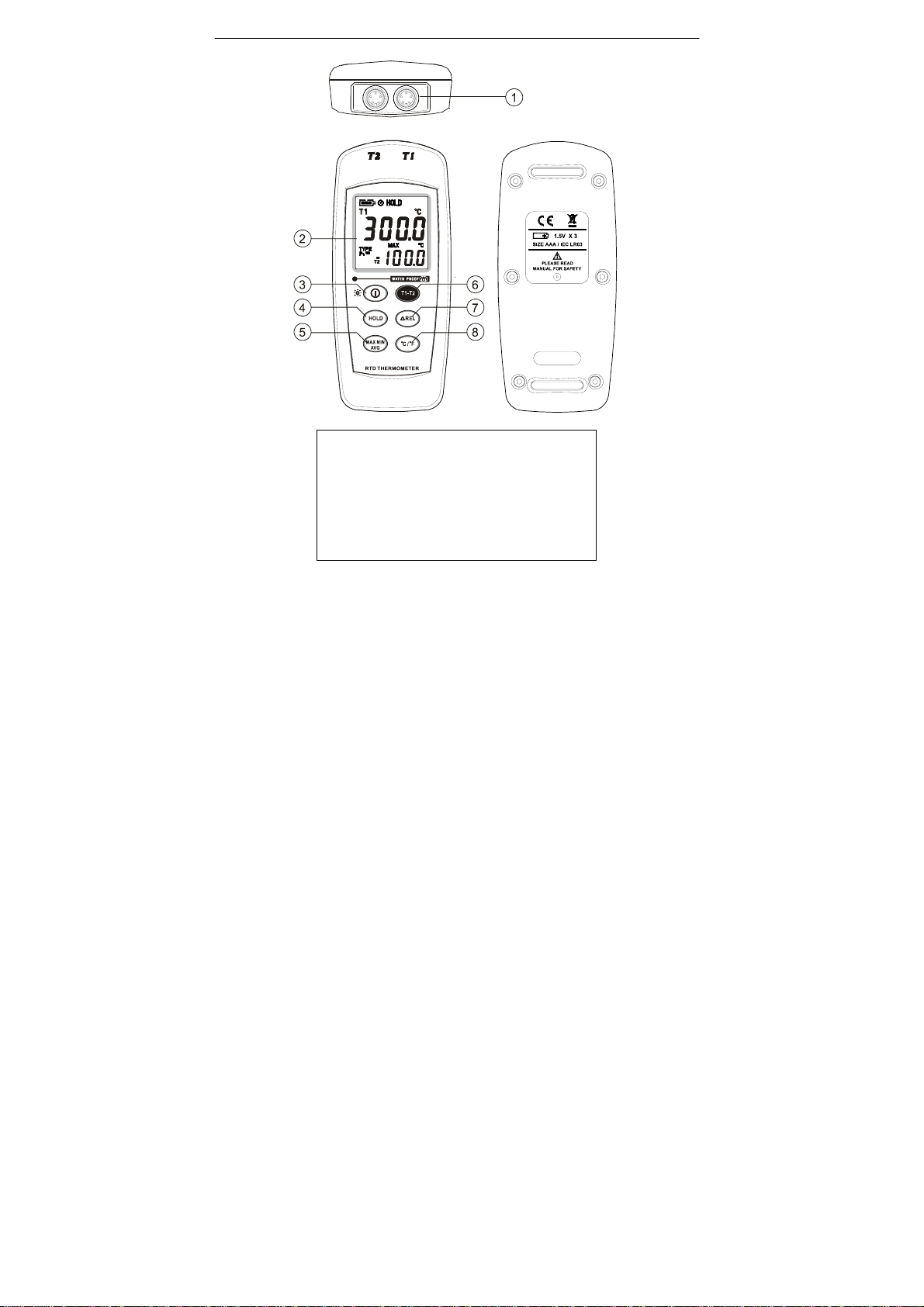
Center 372 User manual

RTD THERMOMETER
3
7
2


372-00 SEP. 2006

CONTENTS
TITLE PAGE
1. Introduction………………………………………………….………1
2. Specifications………………………………………………………..1
3. Symbol Definition and Button Location……………………......3
4. Operation Instructions……………………….…………………....5
4.1 Power-Up & Back Light Operation....................................... 5
4.2 Connection the Temperature Probe………...........................5
4.3 Selecting the Temperature Scale……………..……………… 5
4.4 Data-Hold Operation……………………………………………5
4.5 T1-T2 Operation…………………………………………..…… 5
4.6 Relative Operation……………………………………………...6
4.7 MAX/MIN/AVG Operation………………………………………6
4.8 Auto Power Off…………………………………………………..6
4.9 Low Battery Condition…………………………..……………...7
5. Temperature Measurement……………………………………..... 7
6. Temperature Meter Calibration Setup.……….………………….8
7. Maintenance.……….………………………………………………13
Replacing the Batteries.……….……………………………….... 13
Cleaning.……….………………………………………………..….14
8. Temperature Probe.……………………………………………….15

RTD THERMOMETER
1
1. Introduction:
This instrument is a digital thermometer for use with platinum-type
temperature sensor.
Temperature indication follows IEC751 temperature table for PT-type
sensor.
2. Specifications:
Numerical Display: 4 digital liquid crystal display
Measurement Range: -100°C ~ 300°C; -148°F ~ 572°F
Resolution: 0.1°C; 0.1°F;
Sensor types:
Platinum resistance temperature sensor for pt-100, 4 wires.
ALPHA=0.003850, 0.003926, 0.003916 (selectable)
Measurement current: Approx 0.53ma
Maximum Voltage at Temperature couple Input:
60V DC, or 24VrmsAC
Environmental:
ROperating Temperature and Humidity:
0°C ~50°C (32°F ~ 122°F) ; 0 ~ 80% RH
RStorage Temperature and Humidity:
-10°C to 60°C (14°F ~ 140°F); 0 ~ 80% RH
RAltitude up to 2000 meters.
Accuracy: at ( 23 ± 5°C )
Range Accuracy
-100°C ~ 300°C ±(0.1% reading + 0.4°C)
-148°F ~ 572°F ±(0.1% reading + 0.8°F)
Temperature Coefficient:
For ambient temperatures from 0°C ~ 18°C and 28°C ~ 50°C, for
each °C ambient below 18°C or above 28°C add the following
tolerance into the accuracy spec.
0.01% of reading + 0.03°C ( 0.01% of reading + 0.06°F )

RTD THERMOMETER
2
Note:
The basic accuracy Specification does not include the error of the probe
please refer to the probe accuracy specification for additional details.
Sample Rate: 2 times per second for each channel
Water resistance: IP67
Dimension: 150 ×66 ×31mm
Weight: 180g Approx.
Accessory:
Pt-100 Probe(class A, Alpha=0.003850), Battery, Instruction Menu
Option: Connection Cable
Power requirement: Battery 1.5V X 3 size AAA
Battery Life: Approx. 100hours with alkaline battery

RTD THERMOMETER
3
3. Symbol Definition and Button Location:
-
: This indicates that the minus temperature is sensed.
°C °F : Centigrade and Fahrenheit indication.
Pt 100 : Platinum Type Indication
HOLD : This indicates that the display data is being hold.
MAX : The Maximum value is now being displayed
MIN : The Minimum value is now being displayed
AVG : TheAverage value is now being displayed.
△REL : The reading is now under Relative Mode.
: The Battery power potential indication.
: This indicatesAuto Power Off is enabled.
T1-T2 : This indicates the value below is T1-T2 sensor.

RTD THERMOMETER
4
○
1Pt type temperature sensor connector
○
2LCD display
○
3Power ON/OFF button & Back Light button
○
4HOLD button
○
5MAX MIN Average control button
○
6T1-T2 button
○
7Relative readout button
○
8°C , °F control button

RTD THERMOMETER
5
4. Operation Instructions:
4.1 Power-Up & Back Light Operation
The ○
Ikey turns the thermometer ON or OFF and backlight ON &
OFF.
Press it once to turn ON the Thermometer.
Press it again for moment to turn ON or OFF backlight.
Press and hold this button 3 second to turn Off the power.
4.2 Connection the temperature probe
For measurement, plug the temperature probe into the input
connectors.
4.3 Selecting the Temperature Scale
When the meter was first power on, the default scale setting is set at
Celsius (°C) scale. The user may change it to Fahrenheit (°F) by
pressing “ °C/°F ” button and vice versa to Celsius.
4.4 Data-Hold Operation
The user may hold the present reading and keep it on the display by
pressing the “HOLD” button. When the hold data is no longer needed,
one may release the data-hold operation by pressing “HOLD” button
again.
When the meter is under Data Hold operation, the “△REL”,
and “ °C/°F ”button are disabled.
4.5 T1-T2 Operation:
When this button is pushed, “T1-T2” temperature difference will be
shown on the main LCD display to indicate that the tester is under T1
minus T2 mode.T1 and T2 will be shown on the second display
alternately.

RTD THERMOMETER
6
4.6 Relative Operation:
When one press the “△REL” button, the meter will memorize the
present reading and the difference between the new reading and the
memorized data will be shown on the display. Press the “△REL”
button again to exit the Relative operation.
4.7 MAX/MIN/AVG Operation:
When one press the button the meter will enter the
MAX/MIN/AVG mode. Under this mode the maximum value,
minimum value and average value of latest 8 data is kept in the
memory simultaneously and updated with every new data.
When the MAX symbol is display, the Maximum is shown on the
display.
Press again, then the NIN symbol is on the display and also
the minimum reading.
Press again, the AVG symbol is on the display and also the
average reading.
Press again, MAX, MIN and AVG will blink together. This
means that all these data is updated in the memory and the reading
is the present temperature.
One may press to circulate the display mode among these
options.
When the meter is under operation, “△REL” and “ °C/°F ” are
disabled.
To exit the MAX/MIN mode, one may press and hold for two
seconds.
4.8 Auto Power Off:
By default, when the meter is powered on, it is under auto power off
mode. The meter will power itself off after 30 minutes if no key
operation.
One may press and hold “HOLD” button and then power on the meter
and there will be two successive beeps to indicate that auto power off
is disabled.

RTD THERMOMETER
7
4.9 Low Battery Condition:
The temperature meter incorporates visual low battery indication as
follows:
Battery OK, measurements are possible.
Battery Low, battery needs to be replaced, measurements
are still possible.
Battery exhausted, the battery need to replaced with new
one(size AAA, 1.5V x 3).
5. Temperature Measurement
5.1 Correct Measurement Method:
The temperature sensor is
located at the end of the
metal sheath of the sheath
type TEMPERATURE PROBE.
To accurately test internal
temperature insert the probe
into the item you want to
measure to a distance at least
15 times the diameter of the
sheath.
5.2 Connector Configuration:

RTD THERMOMETER
8
6. Temperature Meter Calibration Setup
Below table diagram shows each button function when user enter
into calibration mode.
Note:
Turn the Power “OFF” before attempting following SETUP.
Setup mode is cancelled during below procedure if “POWER”
button is pressed.

RTD THERMOMETER
9
6.1 Pt type selection
6-1-1.
Press and hold “Power” + “T1-T2” buttons
for 2 seconds to enter setup mode.
6-1-2.
Press “Hold” button to enter Pt αselection
mode.
6-1-3.
Press “Max” button to select between Pt
probe type.
(α=3850, α=3926, α=3916 is circulate)
6-1-4.
Press “°C/°F” button to confirm selection.

RTD THERMOMETER
10
6.2 0 °C Calibration Insert temperature probe into 0°C Deg.
Standard calibrator unit before calibration. Hold
the probe until condition is stabilized before
starting calibration.
6-2-1.
Press and hold “Power” + “T1-T2” buttons
for 2 seconds to enter setup mode.
6-2-2.
Press “REL” button to enter calibration
mode. Enter Pt selection first.
6-2-3.
Press “°C/°F” button to confirm Pt αselection
.
6-2-4.
Press “REL” button to enter calibration
mode.

RTD THERMOMETER
11
6-2-5.
Press “REL” button to confirm present
calibration value.
6-2-6.
Press “°C/°F” button to confirm selection
.
6.3 Recall Default factory setting value
6-3-1.
Press and hold “Power” + “T1-T2” buttons
for 2 seconds to enter setup mode.
6-3-2.
Press “REL” button to enter calibration
mode. Enter Pt selection first.

RTD THERMOMETER
12
6-3-3.
Press “°C/°F” button to confirm Pt αselection
.
6-3-4.
Press “T1-T2” button to enter recall mode.
6-3-5.
Press “°C/°F” button to confirm revert back
to “Default factory setting value”
6-3-6.
Press “°C/°F” button to confirm selection.

RTD THERMOMETER
13
7. Maintenance
Replacing the Batteries
(1) Remove back cover screw to remove cover. Verify polarity and
install new LR03(AAA size) alkaline batteries.
(2) Fit cover properly and tighten screw.
The unit’s back cover are fitted with rubber rings. After replacing the
battery, check that the rubber rings are properly seated before reinstalling
the back cover. Improper seating of the rubber rings will compromise the
unit’s water-resistant structure, and possibly result in damage to the
equipment.

RTD THERMOMETER
14
Cleaning
In order to ensure the accuracy of the thermometer for a longer
period of time you should calibrate it once a year.
Clean the device and the window of the display with a clean, lint-free,
antistatic and dry cleaning cloth.
Do no use cleaning agents thatcontain carbon or benzenes, alcohol
or anything similar to clean the product since these substances damage
the surface of the measuring instrument. Moreover, these fumes are
hazardous to health and explosive. Do not use tools with sharp edges,
screwdrivers, metal brushes or anything similar to clean the device.

RTD THERMOMETER
15
8. Temperature Probe
8.1 Piercing type temperature probe
8.2 Piercing type temperature probe Specification
Sensor Type Platinum resistance thermometer
sensor Pt 100(4 wires)
Alpha=0.003850
Accuracy IEC751, class A
±0.15°C±0.002t
(t: measurement temperature)
Measurement Range -100 to 400°C
Temperature Sensor
Dimensions Approx. ∅3.2mm(∅0.125”)
Temperature Sensor
Length Approx. 120 mm(4.72”)
Cable Length Approx. 1100 mm(43.3”)
Water-resistant EN60529:1991
IP67

This manual suits for next models
1
Table of contents
Other Center Thermometer manuals