• Installtheleverintothebarandpullthehydraulichosetoensuretheleveristight.
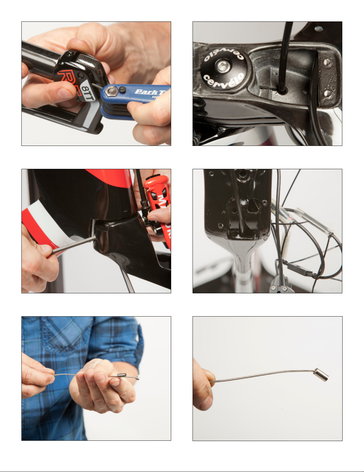
• Usinga2mmAllenwrench,tightentheretentionscrewoneithersideoftheleverbladetolocktheleverinplace(Figure35,Figure36,Figure37).
• Feedtheendofthehydraulichosethroughthebar,anyspacers,andthefairingmount.Onceinstalled,lightlypullonthehosetoremoveanyslack(Figure38).
NOTE:Becarefulnottokinkthehydraulichoseduringthisstep.
Magura Rear Brake Lever Installation using the 3T Aduro Aerobar
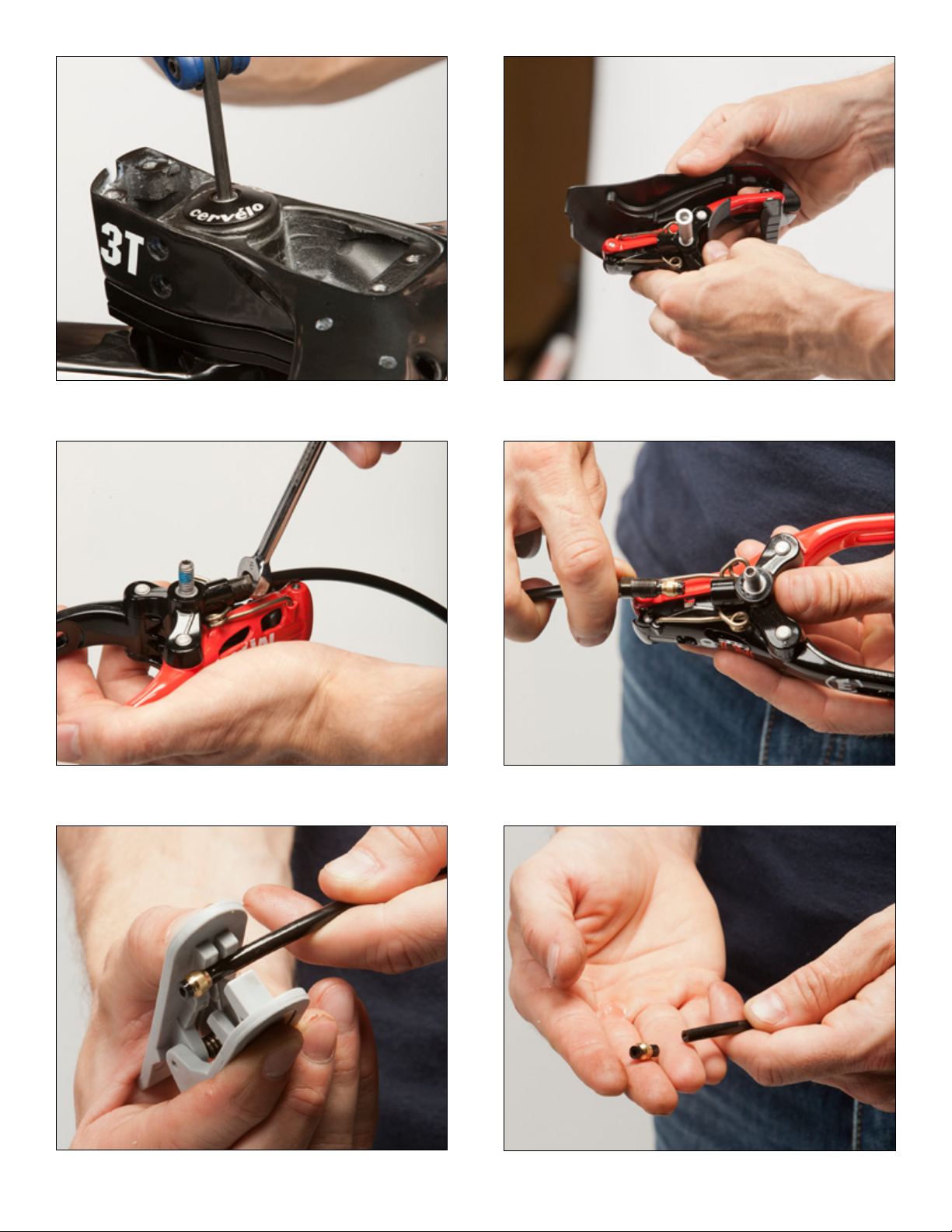
• Removethehydraulichosefromthecaliper(NOTTHELEVER)usingan8mmopenendedwrenchandplacethecaliperaside.Donotsqueeze
thecaliperbrakearmsnorthebrakeleverasmineraloilwillescape(Figure27,Figure28).
• UsingtheMagurahosecutter(orasharpknifeonahardsurface)cutthehosejustabovetheolive.Removethethreadednutandsetasidewiththecaliper
(Figure29,Figure30,Figure31).
• Putaslightbendintheendofthehydraulichoseandfeeditthroughthebar(Figure32,Figure33,Figure34).
• Installtheleverintothebarandpullthehydraulichosetoensuretheleveristight.
• Usinga2mmAllenwrench,tightentheretentionscrewoneithersideoftheleverbladetolocktheleverinplace(Figure35,Figure36,Figure37).
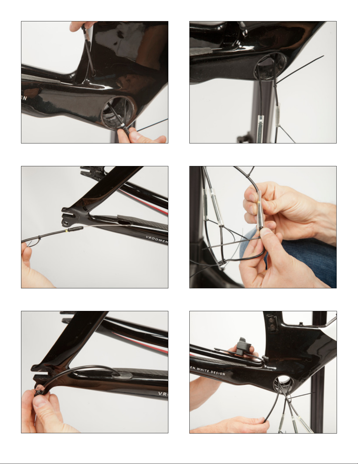
• Feedthehosethroughthebackpartoftheaerobaranddownthroughthemiddleholeinthebottomofthecablebucket(Figure39).
• ThehoseshouldfeedthroughthedowntubeandoutthroughthecableguideholeonthebottomoftheBBshell(Figure40).
Magura Brake Lever Installation using the 3T Aura Pro Aerobar
• Usingan8mmopenendedwrench,removethehydraulichosefromthecaliper.Donotremovethehydraulichosefromthebrakelever(Figure27,Figure28).
NOTE:donotsqueezethecaliperbrakearmsorbrakelever,mineraloilwillescape.
• UsingtheMagurahosecutter(orasharpknifeonahardsurface)cutthehosejustabovetheolive.Removethethreadednutandsetasidewiththecaliper
(Figure29,Figure30,Figure31).
• Putaslightbendintheendofthehydraulichoseforeasierroutingthroughthebasebar.
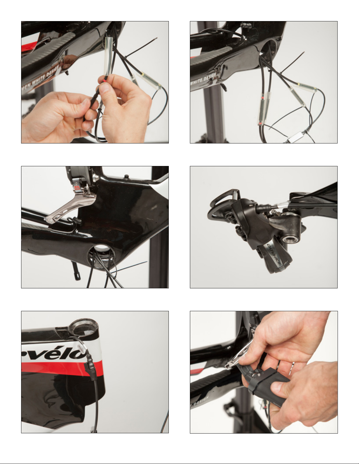
• Slideabrakeferruleontoamechanicalshiftercable(Figure41,Figure42).
• FeedtheferruleandcableintotheundersideoftheAuraProbarandoutthecorrespondingexitforthefrontorrearbrakelever(Figure43,Figure44).
• Installtheferruleontothecutendofthehydraulichose(Figure45,Figure46).
• Pushthehydraulichosethroughthebarwhilelightlypullingontheshiftercable(Figure47).
• Continueuntilyoujustseetheferrulebegintoexitthebar.
• Pullontheshiftercablewithaslightdownwardmotion,whilecontinuingtopushonthehose,tohelpguidetheferruleandhydraulichoseoutof
thebar(Figure48).
• Installtheleverintothebarandpullthehydraulichosetoensuretheleveristight(Figure49).
• Usinga2mmAllenwrench,tightentheretentionscrewoneithersideoftheleverbladetolocktheleverinplace(Figure36,Figure37).
• Repeatthesameprocessfortheotherlever.
Magura Front Brake Caliper Installation
• Cutthehydraulichose1-2mmabovethecenterofthebrakemountholeontheforkcrown(Figure50,Figure51,Figure52).
• Slidethethreadednutonthehose.
• Slidethenewblackolive(includedwiththebrakes)onthehose(Figure53,Figure54).
• Insertthehosebackintothecaliperandensureitbottomsout(Figure55,Figure56).
• Tightenthethreadednut(ensuringnottocrossthread)untiltheolivebeginstodeform.Thenturnthenutanotherhalfturn(Figure57,Figure58).
• Usingthe2mmwasherandlongbrakenut,installthebrakeonthefork(Figure59,Figure60).
Magura Rear Brake Caliper Installation
• Removetheslackfromthehydraulichose,leavingroughlya5mmgapbetweenthehoseandthetopcap(Figure61).
• Cutthehydraulichose1-2mminfrontofthebrakemountholeontheBBshell(Figure62,Figure63).
• Slidethethreadednutonthehose.
• Slidethenewblackolive(includedwiththebrakes)onthehose(Figure64).
• Insertthehosebackintothecaliperandensureitbottomsout(Figure65).
• Tightenthethreadednut(ensuringnottocrossthread)untiltheolivebeginstodeform.Thenturnthenutanotherhalfturn(Figure66).
• GuidethehosethroughtheslotintheBBcableguideandattachtheguidetotheframe(Figure67,Figure68,Figure69).
• Usingthe2mmwasherandshortbrakenut,installthebrakeontotheframe(Figure70,Figure71).
3T ADURO AEROBAR
Di2 Front Wiring Harness Installation
NOTE:FrontWiringHarnessinstructionsarethesameforbothhighandlowmounts.
• ConnecttheFrontWiringHarnesstotheDownTubeE-wire.EachFrontWiringHarnesshas4wires,2foreachleftandrightside.The2wiresof
eachsidearemeanttobeusedwithDi2bar-endshifterandtheDi2shifter/brakeleveronthebasebar.WithMagurabrakes,onlythelongerwires,
toreachtheDi2bar-endshifters,willbeused.Di2basebarshiftingattheMagurabrakeleverisnotpossiblewiththecurrentsystem(Figure72).
• Thelonger,red-codedcableisusedfortherearshifterandthelonger,white-codedcableisusedforthefrontshifter.
• Routethecablesthroughthehighmountandoutthecorrespondingextensionexit(Figure73).