Cervélo R3 Rim User manual

R3 RIM MANUAL | EN
Version 1 I 07.02.2017

1
R3 MANUAL
INTRODUCTION
Welcome to the Cervélo family, and congratulations on your decision to ride an R Series bicycle. The ultra-lightweight engineering of your Cervélo R Series
classic road bikewill help you attackany climbs,and enjoy speed and control on descents. The understated design allows performance to shine through with a
settled ride that lets you respond to the road.
As with the ownership of any high-performance vehicle, it is important to familiarize yourself with its features and service requirements.Please read this manual
before assembly or use.
This document has been prepared to guide you through the assembly of the unique features of the R Series, but is intended only as a supplement to the
assembly instructions offered by your component manufacturer.
Version 1 - 2017-02-07
TABLE OF CONTENTS
Introduction ......................................................................................................1
Frame Features ................................................................................................2
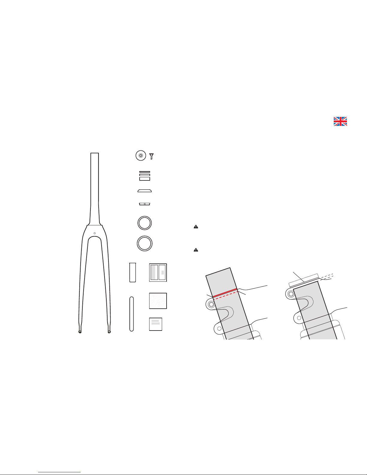
Fork Preparation...............................................................................................3
Small Parts .......................................................................................................5
Frame Preparation............................................................................................6
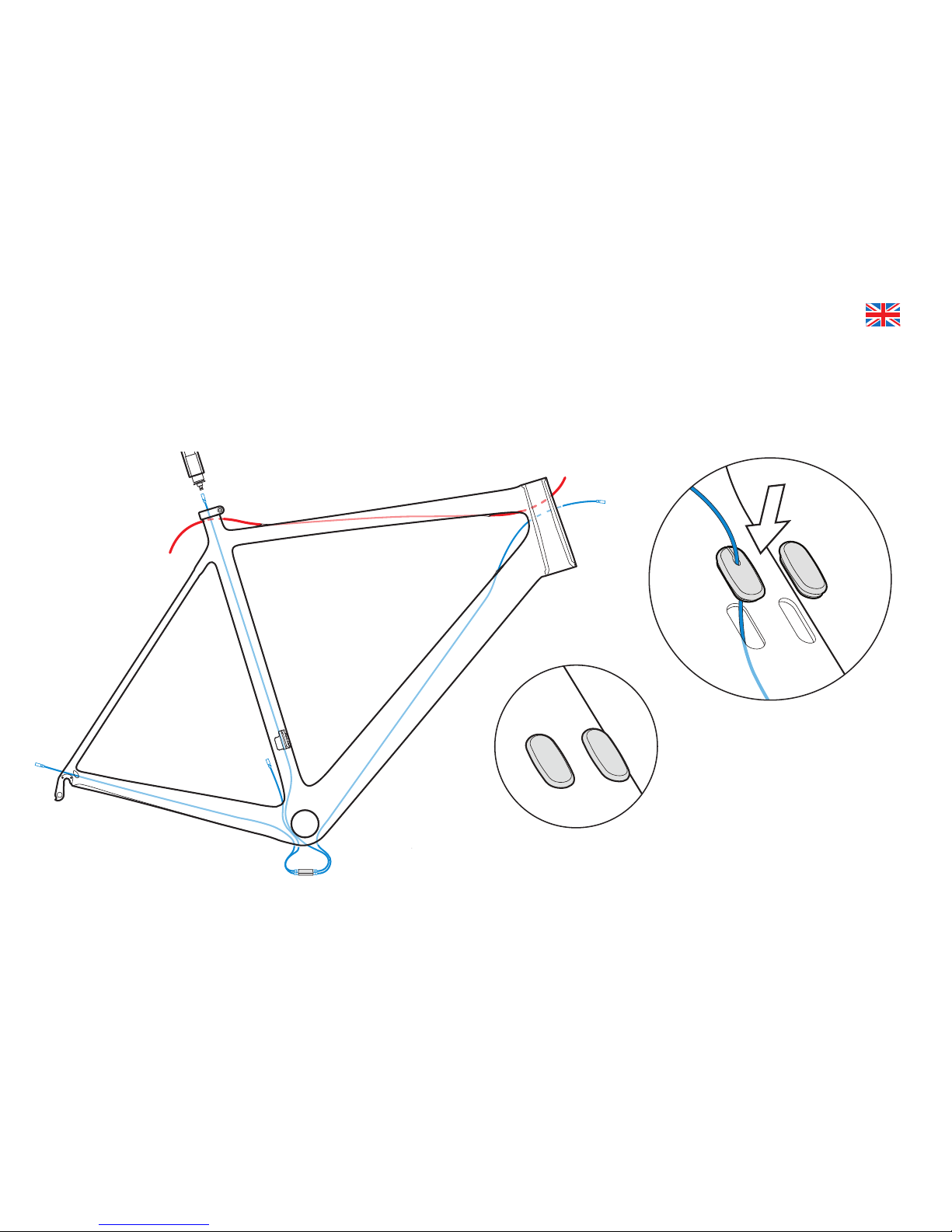
Mechanical Cable Routing ...............................................................................7
Electric Cable Routing......................................................................................9
Seatpost Assembly & Installation...................................................................11
Frame Protection Installation..........................................................................13
Tire Clearance ................................................................................................14

2
FRAME FEATURES
A guide to your Cervélo R3 frame.
Rear dropout cable exit
Front derailleur wire
exit hole, electric and
mechanical
Bottom bracket cable port
Down tube internal
cable ports

3
A
B
Max.
4mm
A 2.5mm spacer under
the Stem Cap is advised
1st Mark 2nd Mark /
Final Cut
C
D
E
F G
H
I
J
A. Stem Cap + 5mm bolt
B. Headset Spacers
C. Bearing Cap
D. Compression Ring
E. Bearings
F. Fork Insert
G. Two-Part Epoxy
H. Mixing Stick
I. Isopropyl Alcohol Wipe
J. Sandpaper (120 Grit)
FORK PREPARATION
1. Apply grease to the bearing seats, and Install the upper & lower
headset bearings into the head tube.
2. Fit the fork provided with your frame into the head tube with the
complete headset, required spacers, and the stem.
3. Apply the minimum pressure needed to ensure the assembly is
fully seated. Mark the steerer tube at the top of the stem.
4. Remove fork and clearly mark the fork steerer tube at a point 4mm
below the rst mark. Take care to verify that this measurement is
correct as this denes the cut line for the steerer tube.
Avoid breathing the dust created during cutting carbon
composite materials.
Your Cervélo frame & fork have been designed to work together. Do
not substitute a different size fork without rst consulting Cervélo
Customer Service to conrm compatibility with your frame.

4
Insert should be ush
with cut end of the
fork steerer tube
5. To trim fork steerer, use only a saw suitable for cutting carbon, and
a cutting guide.
6. Carefully sand a bevel to the inside of the cut end of the steerer
tube to t the insert.
7. Dry t insert to check that it is ush with the cut end of the steerer
tube.
8. Use isopropyl alcohol to clean the inside of the steerer tube and
the outside of the insert.
9. Fully mix the two-part epoxy and apply to the outer surface of the
insert with the wooden mixing stick.
10. Slide the insert into the steerer while rotating it slowly until the
ared end sits ush with the top of the steerer.
11. Wipe away any excess glue from the outside surface of the steerer
tube with the isopropyl alcohol wipe.
12. Set the fork aside and allow it to sit undisturbed for the full curing
period.
Do not attempt to t the fork into a bike prior to the completion of
the full curing period.
Improper cutting of the steerer tube could cause a failure that
results in severe injury or death.
Do not exceed 50 mm maximum total spacer height,
including the bearing cap.

5
SMALL PARTS
Designed to accommodate electronic, mechanical and hydraulic controls, the R3 frame is engineered to provide seamless integration of all shifting systems,
regardless of method or brand. In order to do so, you will require the parts shown below*:
Bottom Bracket
Cable Guide
(Mechanical)
BBG-R-2013
Bottom Bracket
Access Port
Rubber Blanking
Plug (Electric)
GR-BB-GUIDE
Rear Derailleur
Press-In Cable
Stop (Mechanical)
CBS-DRPOUT
Rear Derailleur
Wire Guide
(Electric)
GR-DRPOUT-GUIDE
Rear Derailleur
Blanking Plug
(Wireless)
GR-ST-CLOSED
Mechanical Brake & Shifter
Cable Stop
CBS-TTC-TT-MECH x4
Down Tube Di2 Wire Guide
GR-DT-GUIDE
Hydraulic Hose Guide
CBS-TTC-TT-HYDR x2
Front Derailleur
Wire Hole
Blanking Plug
GR-ST-CLOSED
Rear Derailleur
Hanger
Rear Derailleur
Hanger Fixing
Bolt x2
R Series Rear Derailleur
Hanger Assembly
DRH-R-2012
Down Tube
Wire Hole
Blanking Plug
GR-DT-PLUG
*Complete parts kits are provided with framesets only.

6
Apply Loctite 242 to the xing screws, and
tighten the screws equally to a maximum of
1 Nm.
FRAME PREPARATION
With the wheel installed in
the frame, use a Derailleur
Alignment Gauge to ensure the
hanger is aligned parallel to the
wheel.

7
Install cable housing (with ferrules) into
individual Mechanical Brake & Shifter
Cable Stop until the housing rests
securely in the pockets. Route cables to
bottom bracket, ensuring they are not
twisted together.
MECHANICAL CABLE ROUTING
It is recommended that front and rear derailleur cables be installed after the brake hose has been installed. These routing illustrations are intended as a
supplement to the manufacturer’s installation instructions only. Please refer to the component manufacturer’s service center or website for further information.

8
Route gear cables out of the bottom
bracket cable port. Ensure that the cables
are not twisted together.
The front cable travels across the non-drive side slot, and in the
direction of the seat tube. The rear cable travels along the drive
side slot, and along the chain stay. When complete, snap Bottom
Bracket Cable Guide into place.
Install Rear Derailleur Press-In Cable Stop. As per manufacturer’s instructions, install rear derailleur on rear
derailleur hanger, cut appropriate housing length, and attach cable.

9
Route Di2 wire to the bottom
bracket through the Down Tube Di2
Wire Guide. Seal remaining cable
port with the Top Tube Cable Plug.
ELECTRIC CABLE ROUTING
It is recommended that electric cabling and junction points be installed after the brake hose has been installed. These routing illustrations are intended as a
supplement to the manufacturer’s installation instructions only. Please refer to the component manufacturer’s service center or website for further information.
For wireless systems use two
Top Tube Cable Plugs.

10
With all wires inside, cap the bottom bracket
access port with the Bottom Bracket Access
Port Rubber Blanking Plug.
Install the Rear Derailleur Wire Guide.
For wireless systems install the Rear
Derailleur Blanking Plug.

11
SEATPOST ASSEMBLY & INSTALLATION
Zero setback seatpost
1. Apply a light coat of carbon
assembly compound to the upper
face of the Seatpost, making sure to
cover area around the adjustment
slots.
2. Locate saddle rail between upper
and lower clamps, and place on
Seatpost.
3. With alignment washers installed,
attach assembly to Seatpost, by
tightening lightly greased xing
bolts, alternating between the two
sides each 1/2 turn. Once saddle
is adjusted, tighten xing bolts to a
maximum of 8 Nm.

12
1. Apply carbon assembly paste
to the frame and mount the
Seatpost Clamp.
2. Insert the seatpost into the frame,
and adjust height and alignment.
Torque the Seatpost Clamp bolt
to 6 Nm maximum.
Press the Di2 battery into
the R-Series Internal Battery
Holder and attach the cable
according to manufacturers
instructions.
Insert the assembled
battery and holder
into the seatpost.

13
FRAME PROTECTION INSTALLATION
Clean the chain stay using isopropyl
alcohol. Install the Chain Stay Guard
by removing adhesive backing, and
xing the guard to the frame. The
bottom rearward edge should be
12mm from the front edge of the
Rear Derailleur Hanger.
Install chain catcher when installing the front
derailleur. Complete nal adjustment with the chain
in the small chainring and largest cassette cog.
Tighten the connecting bolt to 4 Nm.
12mm
Install the front
derailleur using the
bolt provided with the
derailleur. Torque to the
derailleur specications.

14
Your Cervélo bicycle complies with the ISO 4210-2:4.10.2 standard for tire clearance. In order to comply with these safety standards and maintain your Limited
Lifetime Warranty, a minimum of 4mm of clearance must remain between the tire and any frame element. Due to the growing complexity of tire and rim interfaces,
Cervélo recommends identifying the available space before choosing a tire.
1. Measure the space between the chainstays at the
bottom-bracket junction.
2. Measure the space between the seatstays at the
top of the tire.
3. Using the smallest of those two numbers, subtract
8mm (4mm per side) to determine the remaining
space.
4. With the tire installed and fully inated on your
wheel, measure the tire width to ensure that it ts.
Failure to follow these guidelines may result in
damage to the frame not covered by Cervélo
Limited Lifetime Warranty.
TIRE CLEARANCE
4mm
minimum
4mm
minimum

1973K3418004
CERVÉLO EUROPE GMBH
Siemensstraße 1-3
49661 Cloppenburg, Germany
+ 49 (4471) 95855-0
www.cervelo-europe-dealer.com
Table of contents
Other Cervélo Bicycle manuals

Cervélo
Cervélo R5 Disc User manual

Cervélo
Cervélo R5 Disc User manual

Cervélo
Cervélo S5 User manual

Cervélo
Cervélo P5 User manual

Cervélo
Cervélo P5X User manual

Cervélo
Cervélo RCA Instructions and recipes

Cervélo
Cervélo PX Series User manual

Cervélo
Cervélo C SERIES User manual

Cervélo
Cervélo ASPERO User manual

Cervélo
Cervélo S3 2019 User manual

Cervélo
Cervélo P5X User manual

Cervélo
Cervélo R5-CX User manual

Cervélo
Cervélo R5 Disc User manual

Cervélo
Cervélo S5 Instructions and recipes

Cervélo
Cervélo S5 Instructions and recipes

Cervélo
Cervélo S5 2023 User manual

Cervélo
Cervélo SOLOIST User manual

Cervélo
Cervélo multi-speed racing bicycles User manual