Cervélo P5X User manual

P5X MANUAL

INTRODUCTION
Three years of extensive research have resulted in the most advanced triathlon bicycle ever created. Not only engineered to carry you to victory, your P5X has been
designed to support all of your service, nutrition and training requirements seamlessly. Although Cervélo strongly recommends that your bicycle be assembled by your
Cervélo retailer, please take time to familiarize yourself with this assembly guide, as this bicycle contains unique components, and requires an understanding of the
disassembly process for travel.
We thank you for making the choice to purchase your Cervélo P5X, and we hope that you enjoy the many hours you will spend with us.
This document has been prepared to guide you through the assembly of the unique features of the P5X, but is intended only as a supplement to the assembly
instructions offered by your component manufacturer. Please pass these instructions to the consumer along with the completed bicycle.
TABLE OF CONTENTS
Version 2 - 2017-06-07
Introduction ......................................................................................................1
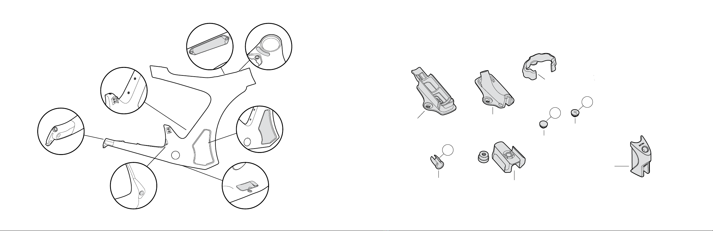
Frame Features ................................................................................................2
Small Parts .......................................................................................................3
Frame Storage Cases.......................................................................................4
Aerobar Components Overview .......................................................................5
Fork Installation ................................................................................................7
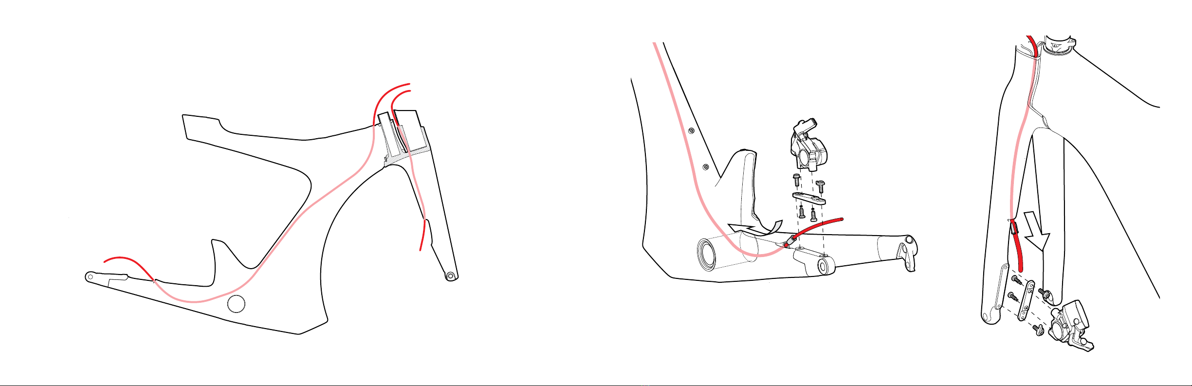
Brake Housing Installation................................................................................8
Basebar Wiring...............................................................................................10
Basebar Installation........................................................................................11
Riser Assembly...............................................................................................12
Extension and Pad Mount..............................................................................13
Arm Cup and Pad Installation ........................................................................14
Multi-Bend Extensions ...................................................................................15
Aerobar Assembly Installation........................................................................16
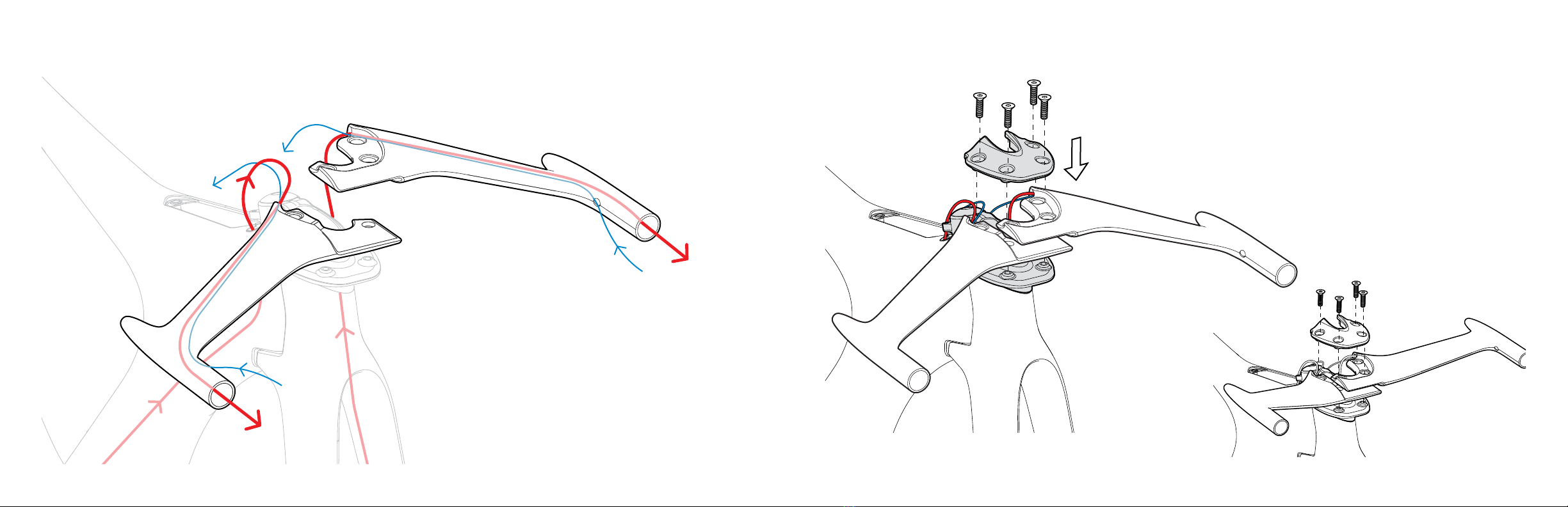
Electric Cable Routing....................................................................................17
Stem Cover Installation ..................................................................................19
Mechanical Cable Routing .............................................................................21
Smartpak Installation......................................................................................23
Speedcase Installation ...................................................................................25
Internal Routing Guide Installation .................................................................26
Stealthbox Installation....................................................................................27
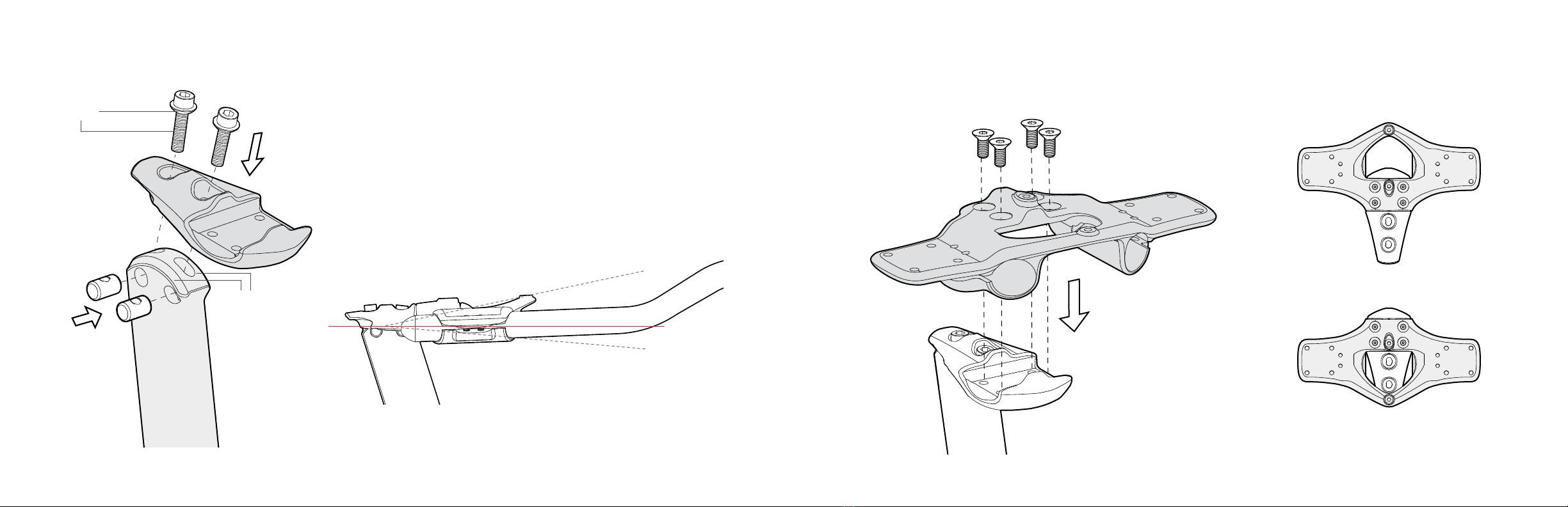
Seat post Assembly ......................................................................................28
Cutting Seat Post ..........................................................................................30
Through-Axle Wheel Installation.....................................................................31
Appendix: P5X Fork Owner's Instructions .....................................................33

x2
x2
x2
2 3
SMALL PARTS
Designed to accommodate electronic, mechanical and hydraulic controls, the P5X frame is engineered to provide seamless integration of all shifting systems,
regardless of method or brand. In order to do so, you will require the parts shown below:
BB Battery Mount
MT-PXBINT
BB Cable Guide
BBG-PX110
Bushing for Brake Hose
BU-DH1290 Internal Routing Guide
CBG-MPXINTF
Seat Post Clamp
SPC-P5X110
Wire Clip
BRW-MPXDi2
E-Wire Grommet
Open Type
GR-BEC-OPEN
Top Tube Routing
Guide
GR-MPXTT
E-Wire Grommet
Closed Type
GR-BVT-TT-S5
FRAME FEATURES
A guide to your Cervélo P5X frame.
Rear dropout cable exit
hole, electric and
mechanical
Front derailleur wire
exit hole, electric and
mechanical
Bottom bracket cable
and battery port
Stealthbox storage
port.
Top tube internal
cable port
Smartpak in-frame
compartment port
Speedcase
mounting points.

4 5
AEROBAR COMPONENTS OVERVIEW
Basebar Plate
Stem
Riser Post
Clamp
Riser Post
Angle Adjustment Plate
Extension and Pad Mount
Multi-Bend
Extensions
Arm Cups and Pads
Base Bar
FRAME STORAGE CASES
Speedcase
Stealthbox
Smartpak
(In frame portion)
Smartpak

6 7
FORK INSTALLATION
1. Check the stem, and headset components to make sure there are no sharp or rough edges on any of
the surfaces which could cut or damage the steerer tube. If any rough edges are detected, have the
components repaired (sharp edges removed) or replaced before proceeding.
2. Press the upper and lower headset bearings into the frame, and insert the fork into the head tube.
3. Slide the compression ring onto the steerer, and down until it fully seats in the top of the upper headset
bearing. The split in the compression ring must be oriented toward to left or right side of the steerer –
never towards the front or back.
4. Slide the stem onto the fork steerer oriented as shown. Note the stem must engage both the fork steerer
and the external steerer. Do not use grease on the fork steerer.
5. Lightly grease the threads of the stem top cap bolt, and the stem clamp bolts.
6. Place the stem cap on top of the stem and insert the greased bolt through the cap to engage with the star
nut. Tighten the bolt only enough to remove all play from the headset, and ensure that the fork still rotates
freely.
7. Tighten the greased stem bolt(s) to the steerer using a torque wrench. Tighten the bolts evenly and
alternately to a maximum of 5 Nm.*
8. As a nal check ensure that the fork rotates freely in the head tube without any play or binding. If any
problem is detected, loosen the bolts and perform steps 6) to 7) again.
*Do not exceed the maximum torque specification for the stem. Correct tightening force on fasteners
– nuts, bolts, screws – on your bicycle is very important. Too little force, and the fastener may not hold
securely. Too much force, and the fastener can strip threads, stretch, deform or break. Either way,
incorrect tightening force can result in component failure, which can cause you to loose control and
fall. In case of a disagreement or a conflict between any literature on recommended torque values,
always use the recommended torque specification as printed on the component or recommended by
the component manufacturer over any recommendation listed in this manual.
P5X ASSE MBLY

8 9
BRAKE HOUSING INSTALLATION
It is recommended that the hydraulic brake hoses or brake cable housing is installed rst. These routing illustrations are intended as a supplement to the
manufacturer’s installation instructions only. For both hydraulic and mechanical disc brakes, please refer to the component manufacturer’s service center or website
for further information.
1. Route hydraulic brake hose or mechanical brake housing through
the frame and fork.
2. Install calipers as per manufacturer's instructions.
3. Install Brake Hose Bushings to secure hose and housings in place.

10 11
BASEBAR INSTALLATION
Basebar - Low Position
Basebar - High Position
1. Lightly grease the threads of the four M5 stem xing screws.
2. Position both halves of the base bars as shown in the up, or down
conguration as determined during tting.
3. Install the Basebar Plate and hold the assembly in place.
4. Insert the four greased M5 xing screws as shown to x the
basebar into place.
5. Tighten to 6 Nm maximum torque.
BASEBAR WIRING
1. Feed electric cable through each side of the basebar from
the front.
2. With brake lines already installed in frame and exiting from
the top tube cable port, push through from back of bar.
3. Install brake levers as per manufacturer’s instructions.

12 13
EXTENSION AND PAD MOUNT
Setback Position
Forward Position
The Pad and Extension Mount can be
attached in two positions:
1. Attach Pad and Extension Mount to Angle Adjust Plate using
four lightly greased M5 xing screws.
2. Torque to 6 Nm.
RISER ASSEMBLY
+12°
-5°
0°
The riser assembly has +12/-5 degrees of tilt adjustment.
1. Lightly grease the threads and spherical washer faces of the
two angle adjust plate xing bolts.
2. Lightly grease the tilt interfacing surface on both the Stem Riser
Post and the Angle Adjust Plate.
3. Assemble the Stem Riser Post components as depicted left.
4. Tighten to 6 Nm.
Grease
Grease

14 15
Minimum Insertion
MULTI-BEND EXTENSIONS
1. Install and adjust extensions.
2. Torque to 5 Nm.
ARM CUP AND PAD INSTALLATION
1. Attach the Arm Cups to the Extension and Pad Mount using
two lightly greased M5 xing screws.
2. Torque to 6 Nm.
Aerobar water bottle mount.

16 17
ELECTRIC CABLE ROUTING
It is recommended that electric cabling and junction points be installed after the brake hose has been installed. These routing illustrations are intended as a
supplement to the manufacturer’s installation instructions only. Please refer to the component manufacturer’s service center or website for further information.
1. Ensure all wires are located
inside frame, with Shimano
Junction B located to the rear
of the Bottom Bracket.
2. Attach Battery to BB Battery
Mount using 2 zip-ties.
AEROBAR ASSEMBLY INSTALLATION
Attach Wire Clip by sliding over
stem from the rear.
1. Apply a light coat of grease to inside of fork.
2. Apply grease to sliding surfaces within Riser
Post Clamp, and tighten down M3 screw, then
back off by quarter turn.
3. Loosen stem bolts slightly, and install Riser
Post, followed by Riser Post Clamp.
4. Torque Riser Post Clamp to 8 Nm.
5. Retighten stem bolts evenly and alternately to
5 NM.
Grease
M3 Screw

18 19
STEM COVER INSTALLATION
Assemble Stem Cover Access Cap,
by snapping window into place.
1. Fix the Stem Cover to stem using the two supplied
lightly greased M4 bolts.
2. Torque to 1 Nm.
Finish by installing the E-Wire Grommet
Open Type to secure the wires.
1. Attach wire to battery and install BB Battery
Mount in Bottom Bracket cable port.
2. Secure using the included xing screw.
3. Torque to 1 Nm.

20 21
With the brake hose already in place,
install shifter cable housing.
The cable housing runs internally from
the aerobar extensions to the bottom
bracket for the front and directly to the
rear derailleur on the back.
MECHANICAL CABLE ROUTING
It is recommended that front and rear derailleur cables be installed after the brake hose has been installed. These routing illustrations are intended as a supplement
to the manufacturer’s installation instructions only. Please refer to the component manufacturer’s service center or website for further information.
Fit excess electric cable and Di2 Junction A or SRAM BlipBox
inside stem cover, positioning LEDs at lens. Slide end cap down
to snap into place.

22 23
1. If using tray without Smartpak, use supplied
M5 xing screws to mount to frame.
2. Torque to 1 Nm.
SMARTPAK INSTALLATION: USING TRAY WITHOUT SMARTPAK
To attach cover to tray, slide in the back edge
and press down at the front to click shut.
Route rear shifter housing through port on rear dropout.
As per manufacturer’s instructions, install
rear derailleur on rear derailleur hanger,
and attach cable.
1. Route front shifter housing to the bottom
bracket cable guide.
2. Route shifter cable around the guide, and
through the front derailleur wire exit hole.
3. Torque to 1 Nm.

24 25
SPEEDCASE INSTALLATION
1. Remove the drive side door.
2. Secure the Speedcase to
the frame using three lightly
greased M5 bolts xing screws.
3. Torque to 2-3 Nm.
1. A water bottle cage can be attached to the
Speedcase using M5 xing screws.
2. Torque to 1-2 Nm.
Attempting to open Speedcase while riding may result in loss of
control and serious injury.
Ensure that Speedcase door latches are fully engaged before
riding. Failing to do so may result in interference with the pedaling
action, and potentially cause loss of control and serious injury.
SMARTPAK INSTALLATION: USING TRAY WITH SMARTPAK
1. Slide Smartpak into place behind the stem cover.
2. Ensure the rubber tabs on the Smartpak are inside the frame. Lightly
grease the rubber tabs to allow easier installation of the tray.
3. Turn fork to one side. Then unzip and place tray into box pushing into
place through the tray port.
4. Optional Pill Tray can be installed in rear of Smartpak using the
rearward xing screw.
5. Secure to frame, by installing lightly greased M5 xing screws
through holes in Smartpak and tray.
6. Torque to 1 Nm.
Optional Pill Tray

26 27
STEALTHBOX INSTALLATION
To open Stealthbox push up on latch on the rear of the box and
pull back box from the top edge.
To install Stealthbox, insert the bottom edge into the
frame at an angle and pivot up while pressing down
on the latch. Once ush with the frame, release latch
to secure.
Attempting to open Stealthbox while riding may result in loss of
control and serious injury.
Ensure that Stealthbox door latches are fully engaged before
riding. Failing to do so may result in interference with the pedaling
action, and potentially cause loss of control and serious injury.
INTERNAL ROUTING GUIDE INSTALLATION
1. With either water bottle cage or Speedcase installed, locate
the P5X internal routing guide on the lower M5 xing screw,
capturing the brake hose and shift wire/cable.
2. Fix the P5X Internal Routing Guide in place by installing
cable guide xing nut nger tight.

28 29
1. Attach water bottle cage using lightly
greased M4 xing screws.
2. Torque to 2-3 Nm.
1. Apply grease to sliding
surfaces within Seat Post
Clamp and tighten down
M3 screw, then back off by
quarter turn.
2. Apply carbon paste to Seat
Post and insert into frame.
3. Insert Seat Post Clamp,
adjust height, and torque to
8 Nm maximum.
SEAT POST ASSEMBLY
Slide the lightly greased seat post
bottle cage slug, into the seat
post.
Apply grease to splines and
assemble with screw.
If not using the bottle cage attachment, use
the alternate seat post slug.
1. Install saddle mount using lightly
greased M5 xing bolts.
2. Torque to 6-7 Nm.
3. Install lightly greased rail binder bolt,
and install saddle.
4. Torque to 12 Nm.
5. Determine desired angle, and attach
water bottle mount to seat post slug
with M5 xing screw.
6. Torque to 4 Nm.
Grease
M3 Screw

30 31
THROUGH-AXLE WHEEL INSTALLATION
Put axle lever in open position.
To secure the front wheel, install the greased axle,
through the drive side drop out, through the wheel
hub, and rotate to thread axle into opposite fork
drop out until tight.
Once tightened, close lever to lock.
Adjust brakes as per manufacturer’s instructions.
Adjust shifting as per manufacturer’s instructions.
If using an aftermarket wheelset, please refer to
the component manufacturer’s service center or
website for further information.
1. ENSURE THAT FINAL SADDLE HEIGHT IS CONFIRMED AND TESTED.
2. Mark the seat post cutting line, by tracing the lower edge of the seat tube on the
seat post.
3. Remove the seat post.
4. Using a saw with carbon-specic blade, trim excess seat post no more than 5mm
above marked line.
5. Sand and clean cut surface, and reinstall.
CUTTING SEAT POST
Avoid breathing the dust created during cutting carbon composite
materials.

32 33
1. IMPORTANT CUSTOMER INFORMATION
2. INTENDED USE
WARNING: Carbon bicycle forks are subject to wear and stress during their lifetime. If the fork’s useful life is exceeded, it can suddenly and catastrophically fail,
potentially causing serious injury or death to the rider. Scratches, cracks, fraying, and discoloration are signs of stress-caused fatigue and indicate that the fork
is at the end of its useful life and needs to be replaced. While the materials and workmanship of your fork are covered by warranty, this is no guarantee that the
fork will last the full term of the warranty. Product life is often related to the kind of riding you do and to the treatment to which you submit the bicycle & fork.
The fork’s warranty is not meant to suggest that the fork cannot be broken or will last forever - it only means that the fork is covered subject to the terms of the
warranty. For warranty details please visit www.cervelo.com. For information relating to product life please consult with your dealer.
• Cervélo forks are designed and built for road riding, racing, and time-trialing. They are intended to be used for rides on smooth surfaces such as paved roads.
While riding, take care to avoid pot holes, sewer grating, railroad tracks, expansion joints, road or sidewalk construction, debris and other obstructions that
could catch your wheel front wheel and cause a severe impact to the fork.
• Cervélo forks are not designed for use on rough or loose off-road surfaces, or for stunts, jumping, or other aggressive riding. These unintended actions can put
huge and unpredictable stress on the fork, and risks serious damage to both the fork as well as to the rider.
WARNING: Frequent inspection of your fork is important for your safety. Perform an inspection of the fork and bicycle before every ride. Periodic, more detailed
inspection of your bicycle is also important. How often this more detailed inspection is needed depends upon you. Because your dealer cannot track your use,
you must take responsibility for periodically bringing your bike to your dealer for inspection and service. Your dealer will help you decide what frequency of
inspection and service is appropriate for how and where you use your bike.
NOTE: See also Care & Maintenance for details on how to identify damaged parts.
For your safety and understanding, please read these instructions in their entirety. Ignoring these WARNINGS can lead to fork failure, which can result in serious
injury or death. Cervélo cannot accept any liability in the event of failure to comply with the instructions in this manual.
APPENDIX: P5X FORK OWNER'S INSTRUCTIONS
To secure the rear wheel, install the greased axle,
through the non-drive side dropout, through the wheel
hub, and rotate to thread axle into the Rear Derailleur
Hanger until tight.
Once tightened, close lever to lock.

34 35
4. CARE & MAINTENANCE
All riders must understand the fundamental realities of composites:
• Composite materials constructed of carbon bers are strong and light, but when crashed or overloaded, carbon bers do not bend, they break.
• At and near the break, there will be rough, sharp edges and possibly delamination of carbon ber or carbon ber fabric layers. There will be no bending, buckling, or stretching.
• Repeated loading of the fork during use can also create fatigue damage over time. Proper inspection of the fork is critical to ensure your safety while riding.
Before each ride:
• Squeeze the front brake and rock the bike forward and back. Does everything feel solid? If you feel or hear knocking with each forward or backward movement of the
bike, you probably have a loose headset. Readjust the headset as per the Assembly instructions above or have your dealer check it.
• Lift the front wheel off the ground and swing it from side to side. Does it feel smooth? If you feel any binding or roughness in the steering, you may have a tight
headset. Readjust the headset as per the instructions above or have your dealer check it.
• Check the fork for any deep scratches, cracks or discoloration. These are signs of stress-caused fatigue and indicate that it is at the end of its useful life and needs to
be replaced.
• Check the alignment of the front wheel within the fork to ensure no parts are rubbing. Readjust the wheel position if necessary.
During each ride:
• Stop and immediately investigate any new or changes in sound (squeaking/rattling), or feel (soft feel/vibration/exibility) occurring in the area of the handlebars, stem,
fork, or front wheel. Do not ride the bicycle until the cause has been identied and properly resolved.
After a crash or significant impact:
• First, check yourself for injuries, and take care of them as best you can. Seek medical help if necessary.
• Next, check your fork for damage on the spot. Do not ride if any problems with the fork are detected. Bring the fork to your dealer for professional inspection.
• Following any signicant impact, take your bike to your dealer for a thorough check. The entire fork must be inspected for damage – this requires fully removing the
fork from the frame to check all surfaces for cracks or other signs of damage. Replace the fork if any problems are detected.
WARNING: A crash or other impact can put extraordinary stress on a bicycle fork, causing it to fail or to fatigue prematurely. Components suffering from
stress fatigue can fail suddenly and catastrophically, causing loss of control, serious injury or death.
WARNING: If the fork sustains a significant impact, the entire fork must be inspected for damage – remove the fork fully from the frame to check all surfaces.
3. ASSEMBLY
WARNING: Improper fork installation could cause a failure that results in severe injury or death.
1. Check the stem and headset components to make sure there are no sharp or rough edges on any of the surfaces which could cut or damage the steerer tube
(inner or external). If any rough edges are detected, have the components repaired (sharp edges removed) or replaced before proceeding.
2. Press the upper and lower headset bearings into the frame, and insert the fork inner steerer into the head tube.
3. Slide the compression ring onto the inner steerer, and down until it fully seats in the top of the upper headset bearing. The split in the compression ring must be
oriented toward to left or right side of the steerer – never towards the front or back.
4. Slide the stem onto the fork steerer (inner and external). Do not use grease on the fork steerers. The use of Tacx Carbon Assembly Compound™ or equivalent
friction paste is recommended to help secure the stem. This increases friction thus allowing for the tightening torque to be lower.
5. Lightly grease the threads of the stem top cap bolt, and the stem clamp bolts.
6. Place the stem cap on top of the stem and insert the greased bolt through the cap to engage with the star nut. Tighten the bolt only enough to remove all play
from the headset, and ensure that the fork still rotates freely.
WARNING: To avoid damaging the fork, never try to align the stem without first fully loosening the stem’s steerer clamp bolts.
7. Tighten the greased stem bolt(s) to the steerer using a torque wrench. Tighten the bolts to a maximum of 5 Nm
WARNING: Do not exceed the maximum torque specification for the stem. Correct tightening force on fasteners – nuts, bolts, screws – on your bicycle
is very important. Too little force, and the fastener may not hold securely. Too much force, and the fastener can strip threads, stretch, deform or break.
Either way, incorrect tightening force can result in component failure, which can cause you to lose control and fall. In case of a disagreement or a
conflict between any literatures on recommended torque values, always use the recommended torque specification as printed on the component or
recommended by the component manufacturer over any recommendation listed in this manual.
8. As a nal check ensure that the fork rotates freely in the head tube without any play or binding. If any problem is detected, loosen the bolts and perform steps 6
to 7 again.
9. For brake installation, please follow the instructions as provided by the brake manufacturer, and also refer to this P5X Owner’s Manual.

36 37
5. INSPECTION OF COMPOSITE FRAME, FORK, AND COMPONENTS
Cracks
• Inspect for cracks, broken, or splintered areas. Any crack is serious. Do not ride any bicycle or component that has a crack of any size.
Delamination:
• Delamination is serious damage. Composites are made from layers of fabric. Delamination means that the layers of fabric are no longer bonded together. Do not
ride any bicycle or component that has any delamination. These are some delamination clues:
• A cloudy or white area. This kind of area looks different from the ordinary undamaged areas. Undamaged areas will look glassy and shiny. Delaminated areas will
look opaque and cloudy.
• Bulging or deformed shape. If delamination occurs, the surface shape may change. The surface may have a bump, a bulge, soft spot, or not be smooth and fair.
• A difference in sound when tapping the surface. If you gently tap the surface of an undamaged composite you will hear a consistent sound, usually a hard, sharp
sound. If you then tap a delaminated area, you will hear a different sound, usually duller, less sharp.
Unusual Noises:
• Either a crack or delamination can cause creaking noises while riding. Think about such a noise as a serious warning signal. A well maintained bicycle will be
very quiet and free of creaks and squeaks. Investigate and nd the source of any noise. It may not be a crack or delamination, but whatever is causing the noise
must be xed before riding.
Misalignment:
• Check for misalignment of the fork by examining the wheel tted properly in the dropouts. Misalignment of a carbon fork cannot be corrected by attempting to
bend or straighten the fork. If the wheel cannot be centered properly by adjusting the t within the dropouts, do not ride until the fork has been examined by
your dealer, and replaced if necessary.
WARNING: Do not ride a fork (or any bicycle component) with any delamination or crack. Riding a delaminated or cracked fork could lead to complete failure,
with risk of serious injury or death. Please ensure that the suspect component is destroyed, not sold.
Other manuals for P5X
1
Table of contents
Other Cervélo Bicycle manuals

Cervélo
Cervélo RCA Instructions and recipes

Cervélo
Cervélo P5 User manual

Cervélo
Cervélo SOLOIST User manual

Cervélo
Cervélo R5 Disc User manual

Cervélo
Cervélo S3 2019 User manual

Cervélo
Cervélo ASPERO User manual

Cervélo
Cervélo S5 Instructions and recipes

Cervélo
Cervélo P5X User manual

Cervélo
Cervélo multi-speed racing bicycles User manual

Cervélo
Cervélo PX Series User manual