Chenzhu GS8572-EX.R User manual

GS8572-EX.R
GS8572-EX.RTD
GS8572-EX
GYB16.1342
IECEx CQM11.0003
DNV11 ATEX 08694X
CZ.GS8572-EX.11(S)E-5.3/16.11
5
4
1
2
3
3
2
1
XK06-014-00557
Connections
(1)
(2).
(3).
(4).
. This barrier adopts knock-down connector with screw terminals. The
intrinsically safe(IS for short) terminals (blue plugs) should be connected
to hazardous area devices and the non-IS ones (green plugs)to the safe
area devices.
Choose for the harzardous area the blue-marked wires. Its minimum
2
cross section area should be 0.5 mm ,and minimum dielectric strength
should be 500V.
The wirings in safe area and hazardous area must be separated,
and both have protection bushes.
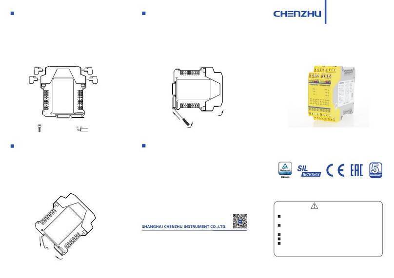
A length of 8mm bared wire is locked by the M3 bolt. See as shown
below.
Installation
The isolated barrier should be located at safe area, according to
the related requirements in IEC60079-17(EN60079-17)and
IEC60079-19(EN60079-19).
GS8500-EX series isolated barrier are designed for mounting on
35mm DIN guide rail.
Installation according to the following steps:
(1). First make the bus-powered outlet locked into the guide rail;(If no
bus-powered function,omit this step);
(2). Make the upside of the barrier locked into the guide rail;
(3). Push the downside of the barrier in the rail.
Disassembly
(1).Insert a screwdriver (its edge length≤6mm)into the downside metal
lock of the barrier;
(2).Push the screwdriver upwards,then prize the metal lock downwards;
(3).Take the barrier out of the guide rail.
(1).Before using, please check again whether the module’s Ex-proof
rating accords to the operation conditions, and also wiring and polarity
are correct.
(2).It is disallowable to test insulativity among the terminals with a
megameter. If necessary, the wires must be cut off before testing ,or the
internal fuse would blow.
(3).Every product has been test strictly before leaving factory. If users
find any abnormality in the module, please contact the nearest agent or
our company.
(4).In 5 years from the delivery date, if the product works improperly
during normal operation, we will repair or replace it without payment.
Non-intrinsically safe terminals Intrinsically safe terminals
Maintenance
Isolated Barrier
User Manual
Caution
Please check whether the product type on the package accords
to the ordering contract;
Read this manual carefully before installation or using. If there is
something unclear, please dial technic support hotline-400 881 0780;
Isolated barrier should be located in the safe area;
Supply voltage is 24VDC, 220VAC is forbidden;
Users are not allowed to dismantle or repair the barrier otherwise
it will induce malfunction.
Please read the instruction manual carefully before use the product,
and please safekeeping.
M3
8.0
YEAR
YEAR
WARRANTY
WARRANTY
Add: Building 6, 201 Minyi Road, Caohejing Hi-Tech Park
Songjiang New Industrial Park, Shanghai 201612, P.R. China
Tel : +86-21-64513350 Fax : +86-21-64846984
Email:chenzhu@chenzhu-inst.com
http://www.chenzhu-inst.com

Number of channels: 1
Supply voltage: 20~35V DC
Current consumption: 40mA (at 24Vdc supply,20mA output)
Safe-area signal:
Current output: 0/4~20mA; Load resistance: R ≤300Ω
Voltage output: 0/1~5V; Load resistance: RL≥20kΩ
(Note: Current output: load resistance: RL≤550Ω, current consumption ≤
55mA need to be customized.
Hazardous-area signal: “Input signal and range list”
Note:
1.”%” of output accuracy is relative to the setting range, should take a
bigger of relative error and absolute error as the output accuracy in application.
2. RTD input, allow max wire resistance 50Ω(3-wire);
3. TC input, transfer accuracy not contain cold junction compensation
error;Every increase in compensation wire 100Ω, cold end error increases 0.2 ℃;
4. TC type B input, the lower limits of temperature range must be greater
than 680℃, to meet the accuracy specifications.
Alarm directions:
Lower than range, LED L falshing, output current ≈3.8mA;
Higher than range, LED H falshing, output current ≈20.8mA;
Breakage, LED L and H falshing at the same time, output current ≈20.8mA;
Short circuit, LED L and H falshing at the same time, output current ≈3mA;
(Notes: breakage alarm current<4mA or other special requirements, be
customized)
Temperature drift: 0.01%F.S./℃
Cold junction compensation: ±1℃(Compensation range: -20℃~+60℃)
Response time: Reach 90% of final value in 1s
Power supply protection: Protect the barrier from reverse supply voltage
destroy
Electromagnetic compatibility: According to IEC 61326-1(GB/T 18268)
Dielectric strength:
Between non-intrinsically safe part and intrinsically safe part≥2500VAC
Between power supply part and non-intrinsically safe part≥500VAC
Insulation resistance:
Between non-intrinsically safe part and intrinsically safe part≥100MΩ
Between power supply part and non-intrinsically safe part≥100MΩ
Weight: Approx.150g
Suitable location:
Suitable IS apparatus:
2-/3-wire thermal resistance, thermal couple, potentiometer
≤
L
Mounting in safe area, be connected with IS apparatus in
Zone 0/1/2,ⅡC、ⅡB、ⅡA, T4~T6 hazardous area.
DNV11 ATEX 08694X
II(1)G[Ex ia Ga]ⅡC -20℃≤Ta≤+60℃
National Supervision and Inspection Center for Explosion Protection and
Safety of Instrumentation(NEPSI)
Compliancy with standard: IEC60079-0(EN60079-0)
IEC60079-11(EN60079-11)
IEC60079-26(EN60079-26)
Ex-marking: [Ex ia Ga] ⅡC
maximum voltage: Um=250V
Intrinsic safety parameter:(7,8,9,10terminals)
Uo=8.5V, Io=20mA, Po=43mW
ⅡC:Co=6.5μF , Lo=3.6mH
ⅡB:Co=60μF , Lo=10.8mH
ⅡA:Co=1000μF , Lo=28.8mH
(1) For distributed inductance and capacitance e.g. as in a cable, allow the
values of capacitance and inductance;
(2) For circuits containing up to 1 % inductance or up to 1% capacitance with
a cable, allow the values of capacitance and inductance;
(3) For connection of the combined inductance and capacitance where both
are greater than 1% of the allowed value (excluding the cable), allow up to 50%
each of the values of capacitance and inductance.
Largest external capacitance (Co) and inductance (Lo) numerical attention
when using the following requirements:
1 2 3
Summarize Operation Conditions
Specification
Isolated barrier converters thermal resistance, thermal couple and
potentiometer signal in hazardous area into 0/4~20mA or 0/1~5V signal. It is
intelligent and has cold junction compensation function, RTD, TC, potentiometer
graduation and range can be configured through computer. The product needs
an independent power supply.Input circuit, output circuit and power supply are
each galvanically isolated.
GS8572-EX.R: Potentiometer
GS8572-EX.RTD: RTD input
GS8572-EX: RTD, TC input
input
(1). The air should not contain any medium corrupting the coat of chro-
me,nickel and silver.Moreover,violent quiver and impact or any cause of
electromagnetic induction (such as big current or spark,etc.)must be avoided
when using.
(2). Operating temperature: -20℃~+60℃
(3). Storage temperature: -40℃~+80℃
(4). Relative humidity: 10%~90%
Intrinsic safety explosion protection loop system
Special requirements have to be confirmed before using the intrinsically safe
explosion loop system(intrinsically circuit) which connected by isolated barrier
and intrinsically safe apparatus in field:
(1) The explosion level of intrinsically safe apparatus should meet the
requirements of operation conditions. The apparatus should pass the explosion
protection test and get the certificate by state-authorized explosion-proof product
certification bodies.
(2) The intrinsic safety parameters of isolated barrier and intrinsically safe
apparatus both are sure, and comply with 12.2.5 of GB 3836.15-2000.
(3) If any parameters are unclear, the system has to be confirmed by stateau
thorized explosion-proof product certification bodies.
0575
T
E
J
-200℃ ~+400℃
-200℃ ~+900℃
-200℃ ~+1200℃
K
N
R
S
B
TC -200℃~+ 1372℃
-200℃ ~+1300℃
-40℃~+ 1768℃
-40℃~+ 1768℃
+320℃ ~+1820℃
Pt100
Cu50
Cu100
-200℃ ~+ 850℃
-50℃~+ 150℃
-50℃~+ 150℃
50℃
50℃
50℃
50℃
50℃
500℃
500℃
500℃
20℃
20℃
20℃
Type Range Min.span Accuracy
0.5℃/0.1%
0.2℃/0.1%
0.2℃/0.1%
0.2℃/0.1%
1.5℃/0.1%
0.5℃/0.1%
0.5℃/0.1%
0.5℃/0.1%
0.5℃/0.1%
1.5℃/0.1%
1.5℃/0.1%
Potentiometer 0kΩ5kΩ~
0kΩ10kΩ~
0.1%
0.1%
RTD
Safety Certificates
118.9mm×106.0mm×12.5mm(GS8572-EX.R、)GS8572-EX.RTD
118.9mm×106.0mm×17.5mm(GS8572-EX)
IN OUT
GS8572-EX
7(-)
6(+)
1(+)
2(-)
- +
9
10
11
Pt100
-
+
11
11
99
1010
+
-
-
+
-
-
IN OUT
GS8572-EX.R
GS8572-EX.RTD
7
8
10
6(-)
5(+)
1(+)
2(-)
- +
7
8
10
7(+)
8(-)
9
10(-)
7
8
10
Note:2-wire connection can not erase lead resistance, error increases.
Application
Safe-area
Hazardous-area
3-wire
potentio
-meter
2-wire
potentio
-meter
2-wire
RTD
3-wire
RTD Power
supply
OUT
Power supply
Safe-area
Hazardous-area
2-wire
RTD
3-wire
RTD TC
Power
supply
OUT
Power supply
Dimensions
Configuration software EasyConfig
EasyConfig is configuration software. Based on the Windows operating
system, the software is easy to use for its friendly interface and the use of
USB interface. The parameters such as the sensor type and range scope
could be set in by users the software.
Version of operating system: Windows XP and above version
Hardware interface: USB interface
Dedicated adapter: USBCOM-MINI(dedicated USB to RS-232 serial
connection)
This manual suits for next models
2
Other Chenzhu Relay manuals
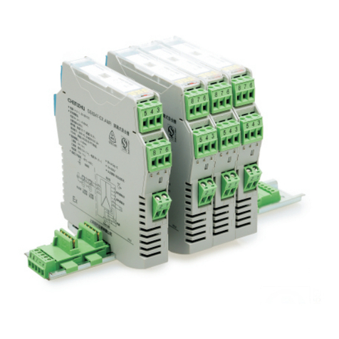
Chenzhu
Chenzhu GS8500 EX Series User manual
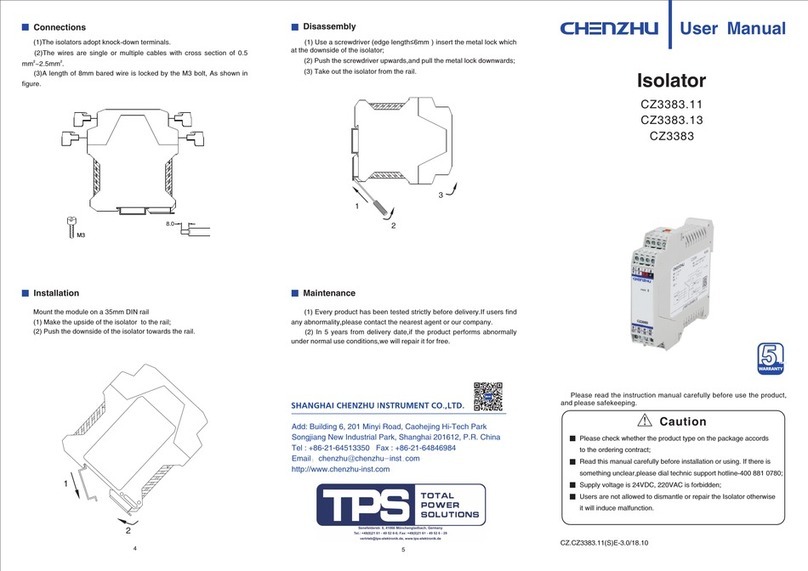
Chenzhu
Chenzhu CZ3383.11 User manual
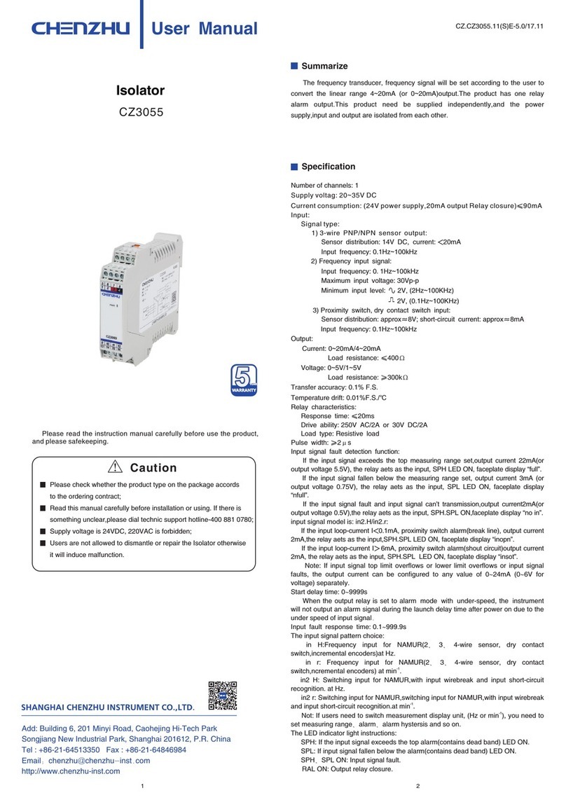
Chenzhu
Chenzhu CZ3055 User manual
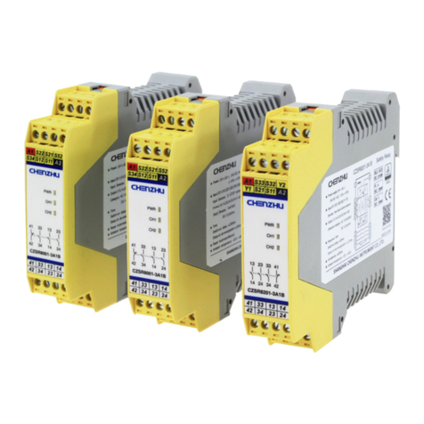
Chenzhu
Chenzhu CZSR8201-3A1B User manual
Chenzhu
Chenzhu CZSR8401-1A User manual
Chenzhu
Chenzhu CZ3074 User manual
Chenzhu
Chenzhu GS8512-EX.12 User manual

Chenzhu
Chenzhu CZ3047T User manual
Chenzhu
Chenzhu GS8547-EX User manual
Chenzhu
Chenzhu CZ3038 User manual

