9
IrDA-9000 Single-Channel 2-Way Sync True Diversity Wireless Microphone
GAIN setting (GT/MT)
Gain control enables the user to set different output levels. GT⑧is for
the use of instrument with high impedance, such as guitar while MT⑨is
for the use of low impedance such as lapel or headset microphones.
Battery installation & indicator
This transmitter requires 2 x AA batteries to operate.
To install, remove the battery cover and slide the batteries according to the correct polarity into
the battery compartment⑩& replace the battery cover.
Note: Batteries contain a corrosive acid that may leak and damage the transmitter when stored
for a long period. Batteries should be removed from the transmitter if it is not to be used for a
prolong period of about 4 weeks or more.
When the transmitter is switched ON a red LED○
12 will blink once to indicate the batteries
installed are in good condition. If the LED remains illuminated, it means the batteries are
weak and a replacement is required.
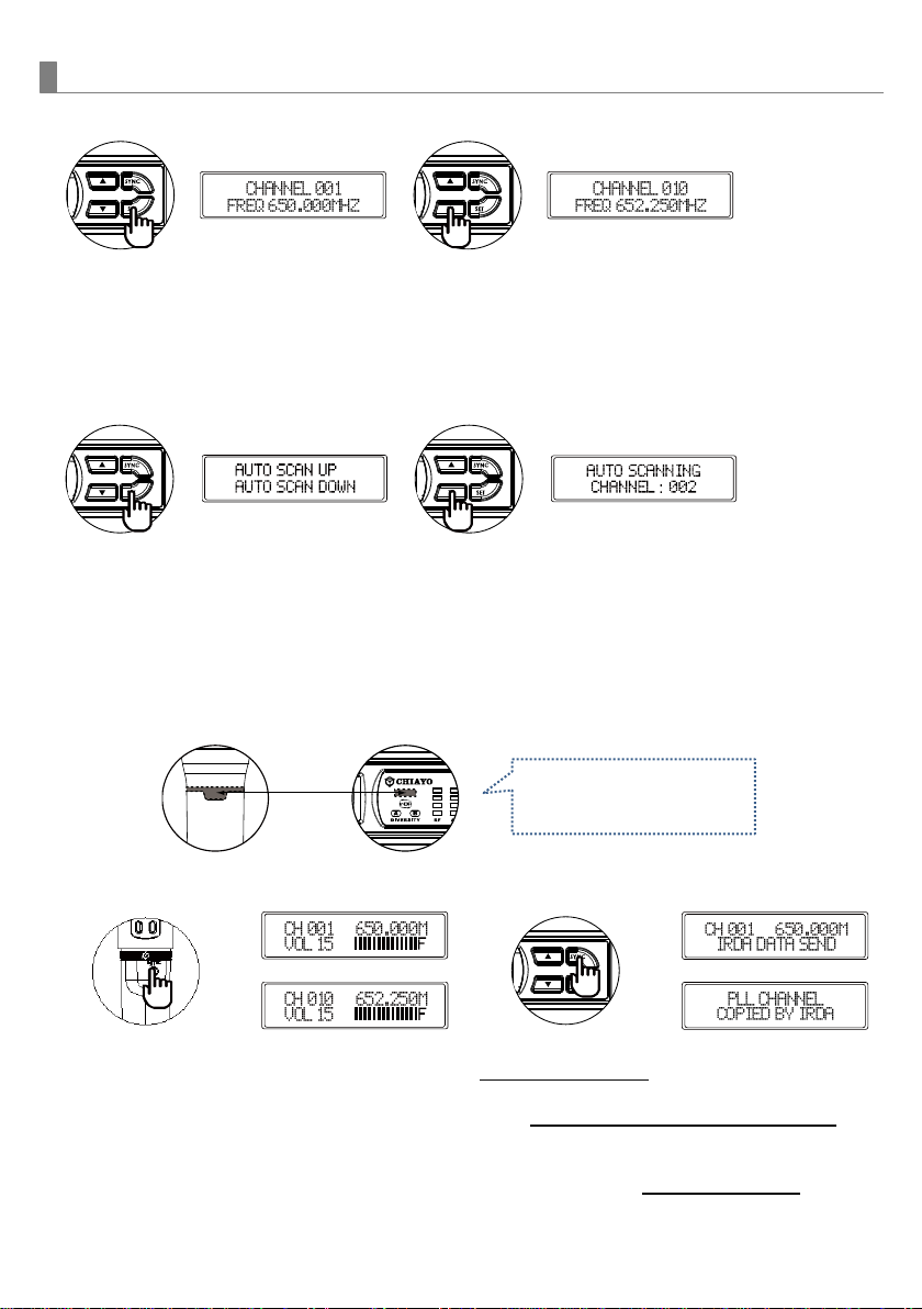
Channel setting
1.Use MENU button⑥to go to the CHANNEL|BATTERY STATUS page.
2. The upper-right channel number will flash to allow changes to be made.
3. Press SET button to change the channel number.
4. 5 seconds after selecting a channel, it will be automatically saved.
Battery type setting
1.Use MENU button⑥to go to the BATTERY TYPE page.
2. Press SET button⑦for 3 seconds, then the cursor “←”will flash to allow changes to be
made.
3. Press SET button to select either NiMH (rechargeable battery) or AKLN (alkaline battery).
4. 5 seconds after selecting a battery type, it will be automatically saved.
Important: NiMH battery must be selected when rechargeable battery is being used. Never
select AKLN (alkaline) when transmitter is intended for charging as alkaline battery isn’t
rechargeable. Wrong battery selection will result in battery sensing electronics to display wrong
and misleading status information.