Pro-face PS400G-T41-E124V User manual

User Manual
PS-400G Series

1
Preface
Thank you for purchasing a Pro-face PS-400G Series Unit (PS400G-T41-E124V), hereafter referred to as
the PS-G unit.
Please read this manual carefully before installing the PS-G unit.
© 2001, Digital Electronics Corporation. All rights reserved.
Windows is a registered trademark of Microsoft Corporation.
All other trademarks and registered trademarks are property of their respective owners.
1 The reproduction,copying ordistribution ofthis equipment orits manual,eitherin whole orin part,
without written permission fromDigitalElectronics Corporation is prohibited.
2 The information provided in this manualis subject to change without notice.
3 Every effort has been made to ensure the information provided in this manualis accurate.Digital
Electronics Corporation would appreciate being informed ofany errors or omissions.
4 Please be aware that DigitalElectronics Corporation shallnot be held liable by the userfor any
damages, losses orthird party claims arising fromthe use or application ofthis equipment.
Important

2
Documentation Conventions
In this manual the following warning symbols are used to indicate important points concerning safe and
proper operation of the PS-G unit. Prior to operating the PS-G unit, be sure to read these points carefully.
Warning Symbols
This manual’s warning symbols indicate the following levels of danger.
The following mark is also used in this manual.
WARNING
CAUTION
Failure to fully comply with points indicated by this
symbol may result in death or serious injury.
Failure to fully comply with points indicated by this
symbol may result in injury or equipment damage.
Indicates actions or procedures that should NOT be
performed.
Indicates actions or procedures that MUST be
performed to ensure proper operation.
Refers to related information or an additional explanation.

3
Essential Safety Precautions
General Handling:
WARNINGS
Do not use the PS-G unit with aircraft control devices, aerospace equipment, central trunk data
transmission (communication) devices, nuclear power control devices, or medical life support
equipment, due to these devices’ inherent requirements of extremely high levels of safety and
reliability.
Do not use the PS-G unit as a warning device for critical alarms that can cause serious operator injury,
machine damage or production stoppage. Critical alarm indicators and their control/activator units must
be designed using stand-alone hardware and/or mechanical interlocks.
Do not use the PS-G unit in an environment where flammable gases are present. This may result in an
explosion.
Do not disassemble or modify the PS-G unit in any way (except for replacing the backlight). Doing so
may result in a fire or an electric shock.
When using the PS-G unit with transportation vehicles (trains, cars and ships), disaster and crime
prevention devices, various types of safety equipment, non-life support related medical devices, etc.
redundant and/or failsafe system designs should be used to ensure the proper degree of reliability and
safety.
Be sure to design your system so that equipment will not malfunction due to a communication fault
between the PS-G and its host controller. This is to prevent any possibility of injury or damage.
Safety and emergency switches must be installed as separate hardware devices.
Do not create PS-G touch panel switches that could possibly endanger the safety of equipment and
personnel. This is because damage to the PS-G, its I/O unit(s), cable(s), and other related equipment
can cause an output signal to remain continuously ON or OFF and possibly cause a major accident. To
prevent this type of accident, design monitoring circuits using devices such as limit switches, etc. to
detect incorrect device movement. Also, to prevent accidents related to incorrect signal output, or
incorrect operation, design your system so that all switches used to control vital machine operations are
operated via a control system that is separate from the PS-G.

4
CAUTIONS
Do not strike the panel of the PS-G unit with a hard, heavy or pointed object, or press the panel with
excessive force. Doing so may result in panel damage or injury.
Do not allow liquids (including water), or metal objects to enter the PS-G unit. This may result in a
malfunction or an electric shock.
Do not block the PS-G unit’s ventilation openings or use it in areas where heat accumulates.
Additionally, do not store or use it under high-temperature conditions.
Do not use or store the PS-G unit in locations subject to direct sunlight, or where excessive dust or dirt
is present.
Since the PS-G unit is a precision instrument, do not store or use it where large shocks or excessive
vibration can occur.
Do not store or use the PS-G unit in environments subject to chemical evaporation (such as that of
organic solvents), or where there are chemicals and acids present in the air.
Do not use paint thinner or organic solvents to clean the PS-G unit.
Important PS-G unit screen data should be backed up regularly.
The installation environment for the PS-G unit must satisfy the following requirements. Failure to do so
may cause the unit to malfunction.
Ambient temperature: 0°C to 50°C
Relative Humidity: 10%RH to 90%RH (Non-condensing)
The LCD panel contains a powerful irritant. If for any reason the panel is damaged and this liquid
contacts any part of your body, wash that area with running water for 15 minutes. Similarly, if any of
this liquid enters your eye, flush your eye with running water for 15 minutes and consult a physician.

5
During Installation:
WARNINGS
Do not use voltage levels other than those specified for the PS-G unit. Use of voltages outside this
range may result in a fire or an electric shock.
PS400G-T41-E124V: DC 24 V±20%
To reduce wire-to-wire or wire-to-earth noise as much as possible, use a low-noise power supply. In
addition, use a twisted-pair power cord.
Separate the PS-G unit’s power line from the power lines to other input/output or motor-driven devices.
Install a surge protector to protect against power surges.
Use a grounding resistance of 100.or less, or use your country’s applicable standard.
Confirm that the main power supply is turned OFF prior to connecting the power cord terminals.
Failure to do so may result in an electric shock.
Since the PS-G is not equipped with a power switch, be sure to connect a breaker-type power switch to
the power cord.
Install the PS-G unit in a vertical position - the unit is not designed to be operated in the horizontal
position.
If the PS-G unit is to be installed in a slanted panel, the panel should not incline more than 30° from the
vertical. If the panel inclines more than 30°, be sure to use forced-air cooling to ensure that the ambient
operation temperature does not exceed 50°C.
During Maintenance:
WARNINGS
Turn OFF the PS-G unit’s power supply prior to performing maintenance. Failure to do so may result in
burns or an electric shock.
Wear gloves when replacing the backlight. Failure to do so may result in burns.

6
PS-400G Series Model Numbers
The PS-400G Series is comprised of the following models.
This manual’s explanation is for the PS400G-T41-E124V unit.
PS-G Unit Application Software
The PS-G unit is pre-installed with the Windows®CE Operating System, which allows the PS-G unit to run
customer-developed applications.
For information concerning application software development environments and software integration
methods, please refer to “PS Series Type G Application Development Kit (ADK) Developer Manual”.
Series Model Description International standards
PS400G-T41-J124V Preinstalled with Windows®CE
3.0 (Japanese).
Input voltage DC24V.
CE Marked, UL/c-UL
(CSA) compliant.
PS400G-T41-E124V Preinstalled with Windows®CE
3.0 (English)
Input voltage DC24V.
CE Marked, UL/c-UL
(CSA) compliant.
PS-400G

7
UL/c-UL (CSA) Approval
The PS400G-T41-E124V and PS400G-T41-J124V is a UL/c-UL listed product. (UL file No. E182139)
The PS400G-T41-E124V and PS400G-T41-J124V conforms as a product to the following standards:
• UL 508 – Industrial Control Equipment
• UL 1604 – Electrical Equipment for use in Class I and II, Division 2, or Class III Hazardous (locations).
• CAN/CSA-C22.2, No. 1010-1
MEASUREMENT AND CONTROL EQUIPMENT
(Safety requirements for electrical equipment for measurement and laboratory use)
PS400G-T41-E124V (UL Registration Model: 2880064-01)
PS400G-T41-J124V (UL Registration Model: 2880064-02)
Installation Precautions
• The PS-G unit must be used as a built-in component of an end-use product.
• The PS-G unit should be installed so that it faces out from a panel.
• If the PS-G unit will be reliant on natural cooling, be sure to install it in a vertical panel. Also, be sure that
the PS-G unit is installed 100 mm away from any adjacent structures or other equipment. If these
requirements are not met, the heat generated by the PS-G unit’s internal components may cause the unit
to fail to meet UL and C-UL (CSA) standard requirements.
UL 1604 — Compliance and Handling Cautions
1. Power and input/output wiring must be in accordance with Class I, Division 2 wiring methods – Article
501 – 4(b) of the National Electrical Code, NFPA 70 within the United States, and in accordance with
Section 18-152 of the Canadian Electrical Code for units installed within Canada.
2. Suitable for use in Class I, Division 2, Groups A, B, C, and D, Hazardous Locations.
3. WARNING: Explosion hazard- substitution of components may impair compliance to Class I, Division
2.
4. WARNING: Explosion hazard – when in hazardous locations, turn the power OFF before replacing or
wiring modules.
5. WARNING: Explosion hazard – confirm that the power supply has been turned OFF before
disconnecting equipment, or confirm that the location is not subject to the risk of explosion.
CE Marking
The PS400G-T41-E124V and PS400G-T41-J124V is a CE marked product that conforms to EMC directives
EN55011 Class A, and EN61000-6-2(EN50082-2).

8
Package Contents
The PS-G unit comes with the following items. After opening the packing box, please confirm that the
following items are included.
PS-G Unit (1)
Model Number: PS400G-T41-E124V
Installation Fasteners (4)
Installation Gasket (1)
(Pre-installed)
Operation Instructions (1)
CD-ROM (1)

9
CD-ROM Contents
The following items are included in the CD-ROM.
Product Name Description
PS-400G Series
User Manual PS-400G Series User Manual PDF file
Acrobat®Reader 5.0 Required for viewing PDF files
(Self-extracting files)

10
Liquid Crystal Display (LCD) Characteristics
• Depending on the contents being displayed and the contrast settings of the PS-G unit, a wavelike pattern
of varying brightness (contouring) may appear. This is not a defect.
• There are minute grid-points (dark and light) on the Display Panel’s surface. This is part of the PS-G
unit’s design and not a defect.
• The colors on the display panel may appear to change when viewed from the side. This is a common
attribute of LCDs and is not a defect.
• An afterimage may appear on the display panel after a single screen that has been displayed for many
hours is changed to a different screen. The display panel will return to normal if switched off for a short
period of time. This is a common attribute of LCDs and is not a defect.
To prevent afterimages:
• Use the PS-G unit’s “Automatically turn off backlight” feature if you need to display the same screen for
long periods.
Refer to “Chapter 3 2.2 Control Panel Settings”.
• Periodically change the screen display.
For more information concerning other PS-G specifications, please contact your local Pro-face sales
representative.
Backlight Burnout Precautions
After the PS-G unit’s backlight burns out the screen will darken and the display will dissappear. If the
operator fails to notice that the backlight is burned out and touches the panel, a potentially dangerous
machine operation error can occur.
WARNINGS
Do not use PS-G touch switches for the control of any equipment safety mechanisms, such as
Emergency Stop switches, etc. that protect humans and equipment from injury and damage.
If your PS-G unit’s backlight suddenly turns OFF, use the following steps to determine if the backlight has
actually burned out.
• If your PS-G is not set to “Standby Mode” and the screen has gone blank, your backlight has burned out.
• Or, if your PS-G is set to Standby Mode, but touching the screen does not cause the display to reappear,
your backlight has burned out.
Also, to prevent accidental machine operation, Pro-face suggests you use the built-in “Disable Input After
Backlight Burnout” feature, that will automatically detect a burnout and disable the designated input
devices.
Refer to “Chapter 3 2.2 Control Panel Settings”.

11
Table of Contents
Preface...................................................................................................................... 1
Documentation Conventions..................................................................................... 2
Essential Safety Precautions .................................................................................... 3
PS-400G Series Model Numbers ............................................................................. 6
PS-G Unit Application Software................................................................................ 6
UL/c-UL (CSA) Approval........................................................................................... 7
CE Marking ............................................................................................................... 7
Package Contents..................................................................................................... 8
CD-ROM Contents.................................................................................................... 9
Liquid Crystal Display (LCD) Characteristics.......................................................... 10
Backlight Burnout Precautions................................................................................ 10
Chapter1 Introduction
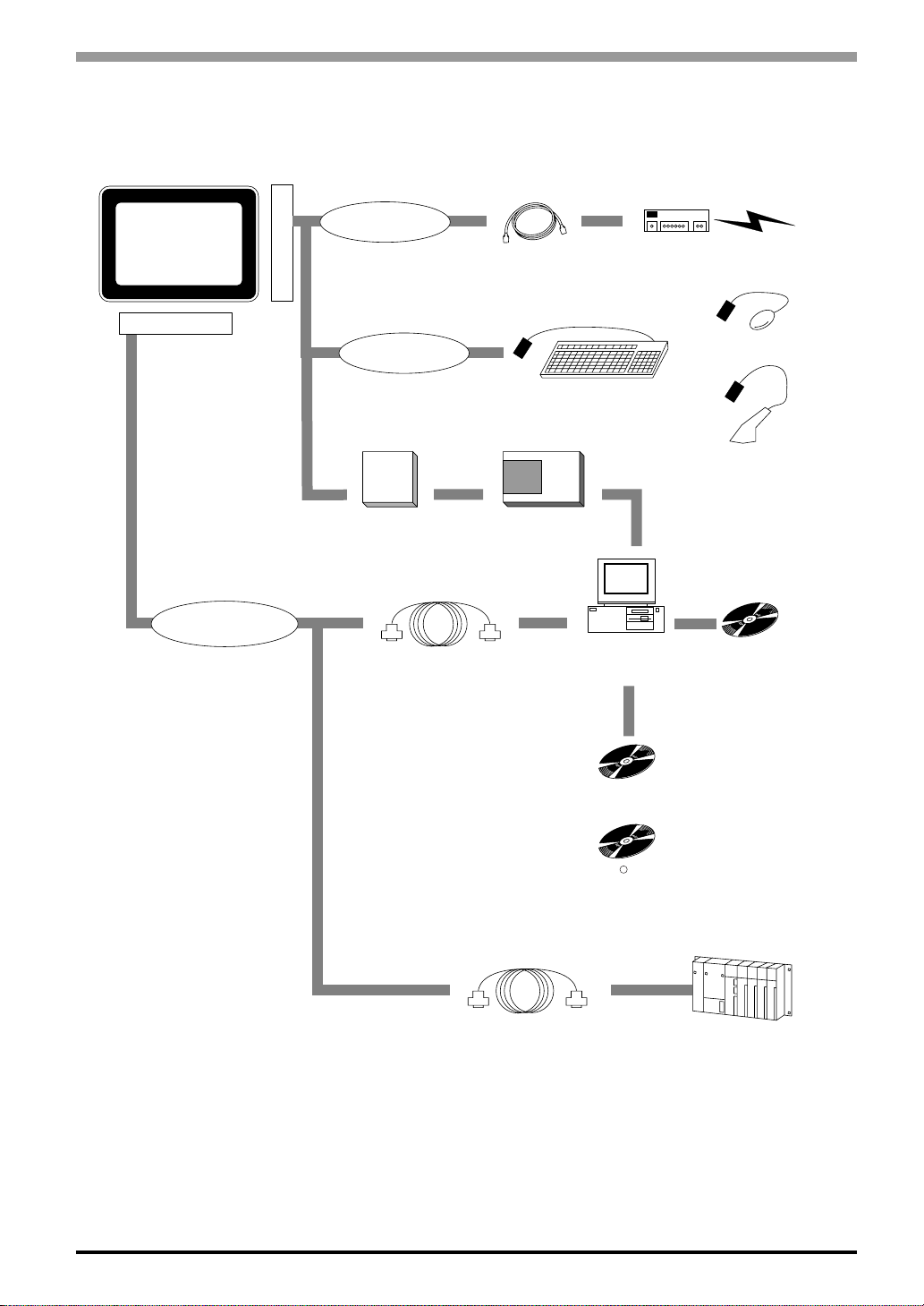
1 System Design................................................................................................... 1-2
2 Part Names and Functions ................................................................................ 1-4
3 Dimensions ........................................................................................................ 1-7
Chapter2 Installation
1 Installation Procedures ...................................................................................... 2-2
2 Connecting the Power Cord............................................................................... 2-7
3 Interface Specifications...................................................................................... 2-9
3.1 Serial Interface ....................................................................................................... 2-9
3.2 Printer Interface .................................................................................................... 2-11
3.3 USB Interface ....................................................................................................... 2-12
3.4 Ethernet Interface ................................................................................................. 2-12
3.5 RAS Interface ....................................................................................................... 2-13
3.6 Sound Output ....................................................................................................... 2-14
3.7 CF Card Insertion and Removal ........................................................................... 2-16
Chapter3 Start Up and Shut Down
1 Start Up ............................................................................................................. 3-2
2 Unit Settings ...................................................................................................... 3-3
2.1 Dip Switch Settings................................................................................................. 3-3
2.2 Control Panel Settings ............................................................................................ 3-4
3 Internal Application .......................................................................................... 3-11

12
3.1 Version Information Psgver.exe........................................................................... 3-11
3.2 Auto Start AutoRun.exe ......................................................................................3-11
3.3 Terminal Services Connection Wizard TsConWiz.exe .........................................3-12
3.4 Applications for Pro-Designer Runtime Installation PDLoad.exe/PortChanger.exe .. 3-14
4 Shut Down ....................................................................................................... 3-14
Chapter4 Maintenance and Inspection
1 Regular Cleaning ............................................................................................... 4-2
2 Periodic Check Points ........................................................................................ 4-2
3 Replacing Consumable Items............................................................................ 4-3
3.1 Replacing the Installation Gasket ........................................................................... 4-3
3.2 Replacing the Backlight .......................................................................................... 4-4
Chapter5 Troubleshooting
1 Troubleshooting Checklists ................................................................................ 5-2
1.1 No display (Windows CE does not start) ................................................................ 5-3
1.2 Touch panel does not respond ................................................................................ 5-3
1.3 Connected devices cannot be used........................................................................ 5-4
Appendices
1 Specifications.....................................................................................................A-2
1.1 Electrical.................................................................................................................A-2
1.2 Environmental.........................................................................................................A-2
1.3 Structural ................................................................................................................A-3
1.4 Performance ...........................................................................................................A-4
1.5 Display....................................................................................................................A-4
1.6 Touch Panel ............................................................................................................A-5
2 RAS Function.....................................................................................................A-6
2.1 Overview ................................................................................................................A-6
2.2 RAS Function - Details ...........................................................................................A-7
2.3 RAS Function Diagram .........................................................................................A-11
3 Accessories .....................................................................................................A-12
Index

1
1 System Design
2 Part Names and Functions
3 Dimensions
Introduction

1-2
PS-400G Series User Manual
1 System Design
*1 Select a cable compatible with your system design. Refer to “Chapter 2 3.5 RAS Interface”.
*2 The DIO unit and the PCMCIA unit cannot be used at the same time.
PS400G-T41-E124V
Expansion unit
interface 2
Expansion unit
interface 1
RAS interface
Sound output
terminal block
Printer interface
Rear of PS-G unit
Connector panel
Printer cable
(PSM-PRCB00) Printer
Pin-jack cable
(GP077-SDAD10) Speaker
User-prepared cable *1 Computer PL Series
Unit Host Controll
er
DIO unit *2
PSG-XY08
PCMCIA unit *2
PSG-PCM00

1-3
1 Introduction
PS400G-T41-E124V
Side of PS-G unit
Connector panel
Host controller (PLC)
CF Card
GP077-CF20 16MB
GP077-CF30 32MB
CF Card Adaptor
GP077-CFAD10
Data Transfer Cable
Supplied with PS series Type G
Application Development Kit (ADK)
PSG-CB01
COM1/COM2
Computer
RS-232C cable
(Commercial type)
PS Series Type G Application
Development Kit (ADK) PSG-DK01
Microsoft eMbedded Visual Tools
For more information, refer to "PS
Series Type G Application
Development Kit (ADK) Developer
Manual".
R
CF
Ethernet interface
10BASE-T cable
(commercial type) Hub Central network line
USB interface
USB keyboard
USB mouse
Bar-code reader
Pro-Designer
PS-DWE01-V**
( indicates data that
changes depending on the version
.)
**

1-4
PS-400G Series User Manual
2 Part Names and Functions
A : DisplayPanel
Displays PS-G unit screen data.
B : Touch Panel
Provides “mouse-less” screen control.
C : Status LED
Indicates the PS-G unit’s status.
Green : Power ON/ Normal operation
At Start Up, the LED lamp changes from Red to Green
Orange : Indicates the RAS function and Backlight burnout
Red : System Error
A, B C
Front

1-5
1 Introduction
D : Power Input Terminal Block
Connects the terminal block to the DC24V power source.
E : Expansion Unit Interface 1 (EXT1)* 1
For DIO units.
F : Expansion Unit Interface 2 (EXT2)* 1
This is a PCMCIA Bus interface.
For PCMCIA units.
G : CF Card Cover
Protects the CF Card slot.
H : CF Card Slot
Accepts a standard CF Card.
I : Printer Interface (PIO)
Connect your printer cable here. (Parallel)
J, K : Serial Interfaces (COM1, COM2)
Connect RS-232C cables here.
L : RAS Interface (RAS)
Connect a RAS cable here.
M : Sound Output Terminal Block.
Connect a speaker or line output here.
*1 Expansion Interface 1 and Interface 2 cannot be used at the same time.
Rear
E F G, H
M
I
DLJK
DC24V
FG
+
-
EXT1
EXT2

1-6
PS-400G Series User Manual
N : Ethernet Interface (10BASE-T)
Connect a 10BASE-T Ethernet cable here.
O : USB Interfaces 1 (USB1)
Connect a USB (USB ver.1.0) compliant device (keyboard, mouse, etc.) here.
Side (Le
ft)
N
O
GR

1-7
1 Introduction
3 Dimensions
PS-400G
Installation Fasteners
11
[0.43]
16 [0.63]
19.5 [0.77]
31 [1.22]
φ10 [0.39]
M5
(
Unit: mm[in.])
204 [8.03]
215 [8.46] 60 [2.36]
8
[0.31]
170 [6.69]
159 [6.26]
(
Unit: mm[in.])
This manual suits for next models
1
Table of contents
Other Pro-face Industrial PC manuals

Pro-face
Pro-face GP-4311HT User manual

Pro-face
Pro-face PS5000 Series User manual

Pro-face
Pro-face GP-4402WW User manual

Pro-face
Pro-face PL-B910 Series User manual

Pro-face
Pro-face GP2500-TC11 User manual

Pro-face
Pro-face PS-4600 Series User manual

Pro-face
Pro-face FP5000 Series User manual

Pro-face
Pro-face PS3700A-T41-ASU-P41 User manual

Pro-face
Pro-face PL-B910 Series User manual

Pro-face
Pro-face PS-3650A Series User manual