Circontrol Raption 150 Compact CCS User manual

Service Manual
Raption 150 Compact


Raption 150 Compact
Service Manual
COPYRIGHT INFORMATION
This document is copyrighted, 2022 by Circontrol, S.A. All rights are reserved.
Circontrol, S.A. reserves the right to make improvements to the products
described in this manual at any time without notice.
No part of this manual can be reproduced, copied, translated or transmitted in
any form or by any means without the prior written permission of the original
manufacturer. Information provided in this manual is intended to be accurate
and reliable. However, the original manufacturer assumes no responsibility for
its use, or for any infringements upon the rights of third parties that may result
from its use.
All other product names or trademarks are properties of their respective owners.


0101
How to service
your Raption
1 — So, Hello! 01
A - Important safety instructions 02
B - Work in a safe environment 03
C - Personal Protective Equipment (PPE) 05
D - Recommended tools 06
2 — Features 07
A - Overview 07
B - Dimensions 08
C - Components overview 09
3 — Control devices 21
A - PC Screen (HMI) 21
B - Mode 4 board 24
C - CCS board 27
4 — Protection devices 29
A - MCCB/Disconnector 30
B - RCD 31
C - MCBs 32
D - RCBOs 33
E - Transient surge protector 34
F - Isolation protection device 35

02
Raption 150 Compact Service Manual
5 — Other components 39
A - Heater system 40
B - Ventilation system 42
C - RFID reader 43
D - DC meter 44
E - Uninterruptible power supply (UPS) 45
F - Power supplies 46
G - Contactors 47
H - Teltonika RUT 240 48
6 — Other optional components 49
A - RFID Reader - Legic 49
B - Omnidirectional tilt switch 51
7 — Troubleshooting & Errors 53
A - Troubleshooting introduction 53
B - Log files 57
C - Decoding the error 59
D - Error code in remote 69
E - Communications errors 71
F - OCPP errors 72
G - Power modules errors 76

03
8 — Maintenance 77
A - CCS holder adjustment 81
9 — Annexes 83
10 — Technical data 85
11 — Need help? 87

Raption 150 Compact Service Manual
01
This manual provides service and maintenance information for Circontrol Charge
Point, which has been designed and tested to allow electric vehicle charging, specified
at IEC 61851 standards.
This document has different sections describing electrical components inside the
Charge Point and a step-by-step maintenance procedure.
It is mandatory to follow the basic security information supplied in this manual to
ensure safe and proper installation.
Failure to follow safety instructions may involve personal injury, equipment damage
and danger of death. CIRCONTROL is not responsible for events arising from such
breach.
ELECTRIC RISK
- This symbol indicates a potentially hazardous situation which, if not
avoided may result in a risk of fire, serious injury or death.
- The Charge Point must be disconnected from any power source before
performing any maintenance, repair or electrical manipulation inside.
ATTENTION!
- Follow the instructions preceded by this symbol, if not respect them or
perform them correctly, may result in minor or moderate injury to the
user, damage to equipment, damage to facilities or other property.
- Handling the equipment can cause injuries as result of the dimension
and weight.
1
Read carefully all the instructions before doing any
maintenance work inside the Charge Point.
THE FOLLOWING SYMBOLS ARE USED FOR IMPORTANT
SAFETY INFORMATION IN THIS DOCUMENT

02
So, hello!
• Read all the instructions before using
and configuring the Charge Point.
• Do not use the Charge Point for anything
other than electric vehicle charging
modes are expected in IEC 61851.
• Do not modify the Charge Point. If
modified, CIRCONTROL will reject all
responsibility and the warranty will be
void.
• Comply strictly with electrical safety
regulations according to your country.
• Do not normally make repairs or
manipulations with the unit energised.
• Only trained and qualified personnel
should have access to the electrical
parts inside the Charge Point.
• Check the installation annually by
qualified technician.
• Remove from service any item that
has a fault that could be dangerous for
users (broken connectors, caps that
don’t close...).
• UseonlyCircontrolsuppliedspareparts.
• Do not use this product if the enclosure
or the EV connector is broken, cracked,
open, or shows any other indication of
damage.
• Adaptors or conversion adapters and
cord extensions set are NOT allowed to
be used.
• Avoid contact with energized electrical
circuits.
• Disconnect the power source before
servicing or repairing electrical
equipment.
• Use only tools and equipment with non-
conducting handles when working on
electrical devices.
• Never use metallic pencils or rulers, or
wear rings or metal watchbands when
working with electrical equipment.
• Enclose all electric contacts and
conductors so that no one can
accidentally come into contact.
• When it is necessary to handle
equipment that is plugged in, be sure
hands are dry and, when possible,
wear nonconductive gloves, protective
clothes and shoes with insulated soles.
• Never handle electrical equipment
when hands, feet, or body are wet or
perspiring, or when standing on a wet
floor.
AImportant safety instructions

03
Raption 150 Compact Service Manual
It is recommended to be very cautious and work safely to control all potential electrical
hazards.
So, the safety rules shown below classify the work to be done depeding on the present
electrical risk, that helps to control risks of injury or death from workplace hazards.
ELECTRICAL RISK
SITUATION EQUIPMENT SITUATION DESCRIPTION
Work without voltage Disconnected -
Live working Equipment connected
without load
Equipment connected
under load (up to 1000 V)
Acting on live elements or
at a distance of less than
70 cm from live elements.
Below the established
safety distance.
Proximity Equipment connected
without load
Equipment connected
under load (up to 1000 V)
Distance greater than 70
cm to live elements.
Steps to be followed during the development of the tests
- Work without voltage unless it is strictly necessary.
- If it is necessary to access the equipment while it is connected (with or without load),
measures should be taken to ensure that all conductive elements are properly protected
by appropriate polycarbonates or insulating enclosures.
- If it cannot be guaranteed that ALL live parts of the equipment are protected by
polycarbonates, live working shall be carried out.
- Guarantee safety distance between risk elements (cabinets, dispensers, wallboxes...)
and the work table (computers, readers, testers).
- Wide and safe access from the door of the box to the work areas. There should always
be a safe escape route.
- Minimise the presence of cables in working areas and put cable protectors.
- Remove all the elements that are not essential for carrying out the tests.
- Have the necessary safety signs to be used as required.
BWork in a safe environment

04
Work without voltage
Live working
It is essential to carry out the following steps in order to successfully perform the
required tests:
1. Disconnect the installation from its source.
2. Check for absence of voltage.
3. Test preparation by placing all the necessary measuring instruments and closing
the doors totally or partially (as much as possible).
4. Energise the installation.
5. Performance of tests making the necessary readings and checks on the tests
STAYING OUTSIDE THE 70 CM PROXIMITY DISTANCE.
6. Lock the installation so that no one authorised has access to the inside part.
Tests MUST be stopped in case of rain, wind or
thunderstorm.
The tests must only be carried out when it is not possible to apply the previous protocol,
only when it is essential to make connections/disconnections with the equipment
connected.
Beforehand, an analysis of the entire installation in which work have to be done must
be carried out in order to protect all live parts with polycarbonates.
It is important that the protective polycarbonate must always be installed after the
connection has been made.
Insulating tools must always be used.

05
Raption 150 Compact Service Manual
It is mandatory that all technical employees wear the following Personal Protective
Equipment (PPE). It must be used for any electrical task such as the described above.
INSULATING SAFETY SHOES
Class 0: 1000V
Dielectric boots recommended
INSULATING GLOVES
Class 0: 1000V AC/1500V DC
HELMET AND FACE SHIELD
Electrical insulation helmet EN397,
EN50365, ANSI Z89.1 20kV
ANTISTATIC MAT
Class 0: Low voltage 1000V
High voltage 36kV
CPersonal Protective Equipment (PPE)

06
DRecommended tools
LAPTOP
MULTIMETER
MULTI-TOOL
USB-RS485
ETHERNET CABLE
SWITCH
ALLEN TOOLS
TORX-TOOLS
SCREW DRIVERS
RATCHET WRENCH
Raption 150 Compact Service Manual
07
2
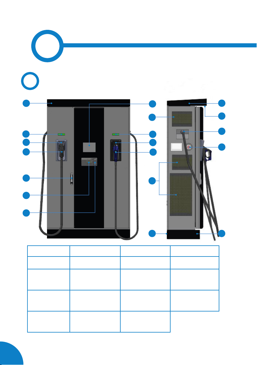
AOverview
Note: Depending on the model, the components can vary.
1
3
2
5
6
4
10
12
8
11
13
14
9
19
17
16
15
7
18
1- Cover 2- CCS light beacon 3- CCS holder 4- CCS connector
5- Handle 6- RFID reader 7- Card payment 8- Touch screen
9- Air inlet Unit 10- CHAdeMO light
beacon
11- CHAdeMO holder 12- CHAdeMO
connector
13- Power M. air
inlet
14- Decorative rear
panel
15- 4G Antenna 16- Courtesy light
17- Exit cable 18- Emergency button 19- Decorative front
panel
08
Features
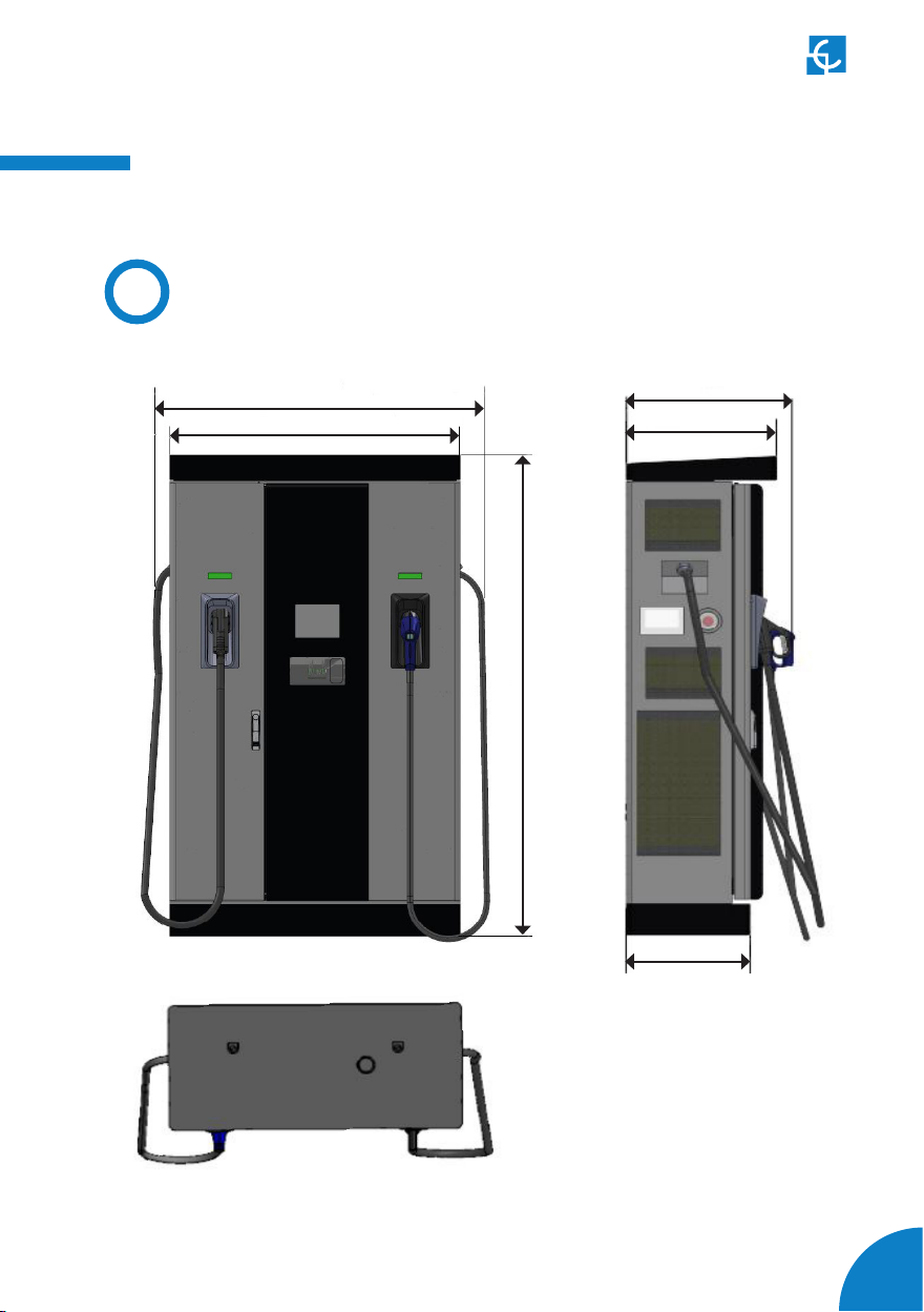
BDimensions
1290
1140
1910
550
610
460
Measures in mm

Raption 150 Compact Service Manual
09
CComponents Overview
Inside the Charge Point it is possible to differentiate four main parts. In the upper part
there are the electronic boards, the electrical protections and the electrical actuators.
In the medium low part there are located the power modules. Next to them on the left,
there is the power input supply section.
The last important part in the Charge Point are both doors.
Electronic boards,
etc
Power modules
Power supply section
Right door
Left door

10
1 — ELECTRONIC BOARDS, ELECTRICAL PROTECTIONS,
ELECTRICAL ACTUATORS - DOOR OPENING -
Step 2
Pull it back manually until you
have access to the rear layer.
To return to the initial position,
simply close by making the
movement in the opposite
direction.
There are located two magnets
between the layers in order the
door could not be accidentally
opened.
Step 1
Locate the tab in the
mid left of this part and
pull it back.
11
Raption 150 Compact Service Manual
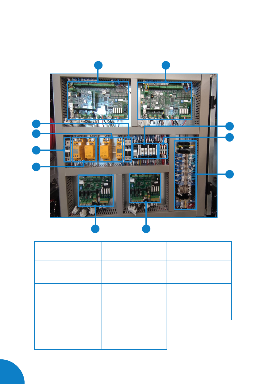
1A — ELECTRONIC BOARDS, ELECTRICAL PROTECTIONS, ELECTRICAL
ACTUATORS - OUTER LAYER COMPONENT OVERVIEW -
7
5
7
11
7
7
7
67
8
2
1
3
4
7
9
1- CHA fuse terminal 6A
(F203.1 /F203.2)
2- Isolation protection
device (B203.1 / B203.2)
3- CCS fuse terminal 6A
(F202.1 / F202.2)
4- Isolation protection
device (B202.1 / B202.2)
5- CCS Mode 4 Control
Board (N226.1)
6- CCS Control board
(N225.1)
7- CHA Mode 4 Control
Board (N228.1)
8- CHA Control board
(N227.1)
9- Relays 24V
(K201.1 / K202.1 / K203.1 /
K321.1 / K321.2 / K350.1 /
K421.1 / K421.2 / K450.1)
10- Distribution supply 12V
(E155.1 / E155.2 / E155.3 /
E155.4)
11- Connection terminal
block
7
10
7
Note: Depending on the model, the components can vary.
12
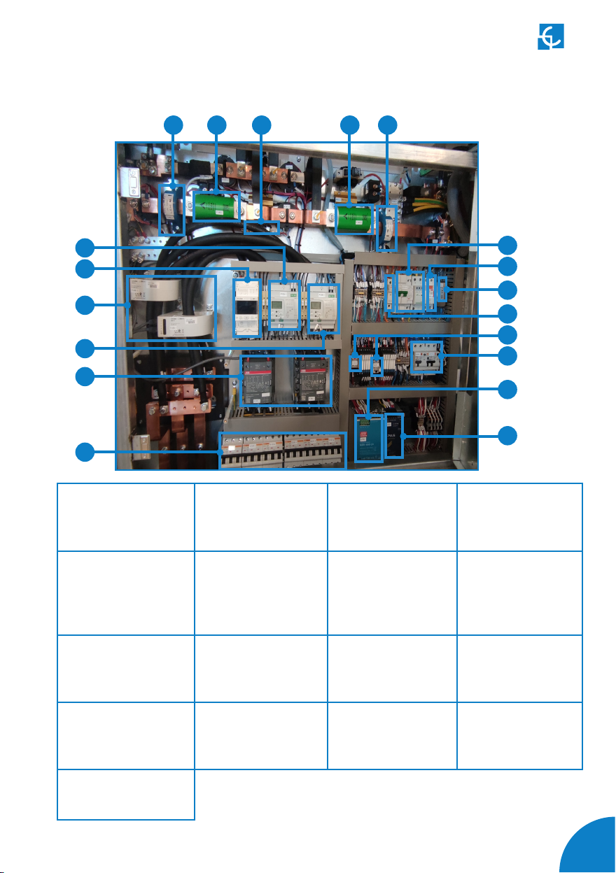
1B — ELECTRONIC BOARDS, ELECTRICAL PROTECTIONS, ELECTRICAL
ACTUATORS - INNER LAYER COMPONENT OVERVIEW -
7
8
3
5
2
1
4
7
10
7
11
7
12
7
15
7
14
1- Three-phase MID
energy meter (P105.1)
2- RCD protection class
B (QD103.1)
3- RCD protection
class B (T105.1 /
T106.1)
4- Three-phase MID
energy meter (P106.1)
5- Contactor for
power modules
(K105.1 / K106.1)
6- Miniature circuit
breaker 3P 50A class C
(Q120.1/Q121.1/Q121.2/
Q122.1/Q123.1/Q123.2)
7- Current transformer
(T140.1 / T140.2)
8- CCS fuse 500A/
CHA fuse 250A (F140.1
/ F140.2)
9- Precharge fuse 2A
(F301.1)
10- Miniature circuit
breaker 2P 20A class C
(Q101.3)
11- RCD 1P+N 25A
30mA class AC
(Q101.4)
12- EMI filter (L101.2)
13- Permanent
overvoltage fuse 25A
(F101.1)
14- Power relay
(K103.2 / K204.1)
15- RCBO 1P 10A class
A (Q109.1 / Q110.2)
16- 24Vdc Power
Supply (G150.1)
17- UPS (G150.3)
7
77
7
7
87
9
Note: Depending on the model, the components can vary.
6
7
16
7
17
7
13
Raption 150 Compact Service Manual
13
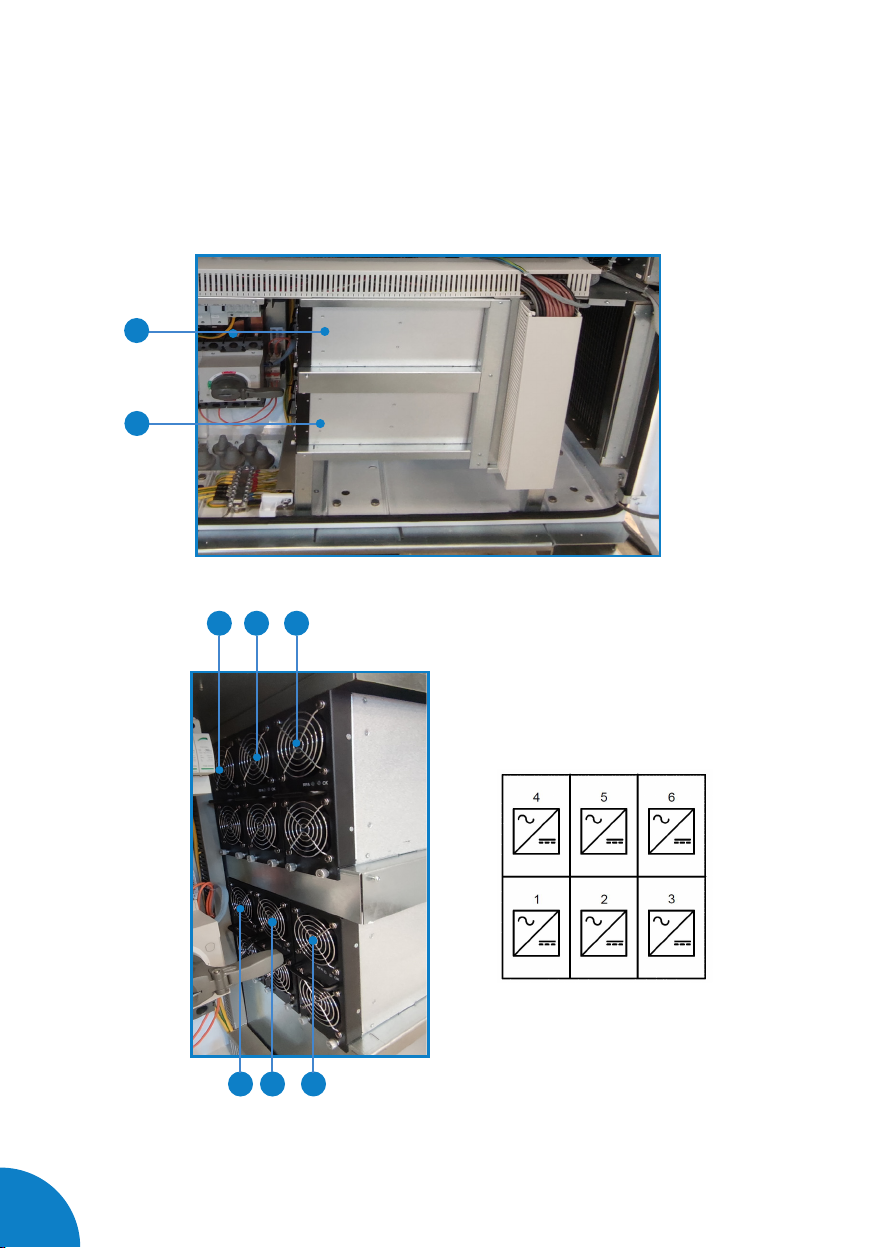
2 — POWER MODULES
7
8
3
4 5
2
Are assembled power modules of 25kW in Raption 51, Raption 52 and Raption 100.
6
1
Power modules layout
(view from left side):
This manual suits for next models
1
Table of contents
Other Circontrol Batteries Charger manuals

Circontrol
Circontrol eVolve T User manual

Circontrol
Circontrol Wallbox eHome CCL-eHOME Series User manual

Circontrol
Circontrol Rapid Series Instruction Manual

Circontrol
Circontrol Wallbox eHome Series User manual

Circontrol
Circontrol eVolve Smart Series User manual

Circontrol
Circontrol CCL-CP1E User manual

Circontrol
Circontrol Post eVolve Series User manual

Circontrol
Circontrol CCL-WBM User guide

Circontrol
Circontrol Raption 150 Series User manual

Circontrol
Circontrol CCS CHA T2C63 User manual


