Circutor Raption 50 Series User manual
Raption 50 Series
INSTRUCTION MANUAL
(M186B01-03-20A)

Raption 50
2Instruction Manual

Raption 50
3Instruction Manual
Disclaimer
Revision log
Date Revision Description
01/18 M186B01-03-18A Initial Version
03/18 M186B01-03-18B Changes in the following sections:
6.2.4. - 6.3.2. - 6.3.4. - 7.3. - 8.1. - 10.
10/19 M186B01-03-19A Changes in the following sections:
4.E.B. - 4.E.F. - 4.E.6. - 5.B.4.2
02/20 M186B01-03-20A
Changes in the following sections:
4.B. - 7.A. - 7.B. - 7.C. - 7.D. - 7.E. - 7.F. - 7.G. -
8.A. - 8.B.
CIRCUTOR, SA reserves the right to make modifications to the device or the unit specifications
set out in this instruction manual without prior notice.
CIRCUTOR, SA on its web site, supplies its customers with the latest versions of the device
specifications and the most updated manuals.
www.circutor.com

Raption 50
4Instruction Manual
Raption 50 Series
Instruction Manual
COPYRIGHT INFORMATION
This document is copyrighted, 2017 by Circutor, S.A. All rights are reserved. Circutor,
S.A. reserves the right to make improvements to the products described in this
manual at any time without notice.
No part of this manual can be reproduced, copied, translated or transmitted in
any form or by any means without the prior written permission of the original
manufacturer. Information provided in this manual is intended to be accurate and
reliable. However, the original manufacturer assumes no responsibility for its use,
or for any infringements upon the rights of third parties that may result from its use.
All other product names or trademarks are properties of their respective owners.

Raption 50
5Instruction Manual
Here is your guide to
use and configure
Raption 50 Series
Disclaimer ...............................................................................................................................3
Revision Log ...........................................................................................................................3
Here is your guide to use and configure Raption 50 Series ....................................5
1. So, hello! .............................................................................................................................8
2. Features ...........................................................................................................................10
A. Main features ..............................................................................................................10
B. Overview .......................................................................................................................11
C. Dimensions ..................................................................................................................12
D. Status Beacon lights .................................................................................................13
E. Connectors ...................................................................................................................14
3. How to use it? .................................................................................................................18
A. General .........................................................................................................................18
B. Starting a charging session ...................................................................................21
C. Special events starting a charge ..........................................................................24
D. Stopping a charging session ..................................................................................29
E. Charging information ................................................................................................31
F. Charging summary ....................................................................................................34
G. Emergency button .....................................................................................................36
H. Connectors status .....................................................................................................37
I. Consulting the connectors status ...........................................................................39
J. Errors .............................................................................................................................43
4. How to configure it? ......................................................................................................44
A. Introduction .................................................................................................................44
B. What is needed? .........................................................................................................45
C. Network topology .......................................................................................................46
D. LAN connection procedure .....................................................................................47
E. Setup Webpage ...........................................................................................................52
A. Dashboard ................................................................................................................53
B. Network .....................................................................................................................59
C. Security .....................................................................................................................61
D. Time ...........................................................................................................................62
E. Integrations ..............................................................................................................63
F. Taris .........................................................................................................................64
G. Services ....................................................................................................................66
H. Firmware ..................................................................................................................68

Raption 50
6Instruction Manual
5. Communications .............................................................................................................70
A. Introduction ...................................................................................................................70
B. Teltonika RUT 240 configuration ............................................................................71
C. Sierra Wireless AirLink LS300 ................................................................................86
6. OCPP Integrations ...........................................................................................................96
A. Introduction ...................................................................................................................96
B. Previous requirements ..............................................................................................97
C. Starting up configuration ..........................................................................................99
D. Checking configuration ...........................................................................................107
7. Monitoring .......................................................................................................................108
A. Introduction ................................................................................................................108
B.PowerStudioclient-Connection...............................................................................109
C.PowerStudioclient-Overview...................................................................................111
D.PowerStudioclient-Devices......................................................................................117
E. PowerStudio client - Graphs ..................................................................................126
F.PowerStudioclient-Tables........................................................................................129
G.PowerStudioclient-Events........................................................................................133
8. Output power setup ......................................................................................................134
A. Introduction ................................................................................................................134
B. Maximum output power tor DC .............................................................................135
C. Maximum output power tor AC .............................................................................140
9. Technical Data ...............................................................................................................142
A. ELECTRICAL DATA Models : TRIO 63, TRIO, DUO, DUO CCS T2S32, DUO CHA
T2S32, CCS and CHA......................................................................................................134
B. ELECTRICAL DATA Model : TRIO 480 V .............................................................. 144
C. GENERAL DATA ........................................................................................................ 145
Need help? ...........................................................................................................................147
Guarantee ............................................................................................................................147

Raption 50
7Instruction Manual

Raption 50
8Instruction Manual
This manual contains all the necessary information for the proper use of the Charge
Point and helps the user to perform charging with a high level of eciency and safety.
The CIRCUTOR Charge Point provides the fastest way to charge electric vehicles
nowadays. Its innovative and original design provides a quick and intuitive way for
recharging the electric vehicles, according to the current regulations. It can carry
out loads into alternating current (AC) and direct current (DC), either individually or
simultaneously.
The unit integrates an intuitive user interface and easy to use, it is an 8” touch screen
by which all necessary for recharging operations are performed. It has been designed
vandal-proof in compliance with all requirements regarding IK indices. In addition, the
Charge Point also has a communications system that allows monitoring and control
remotely via OCPP and use XML parameters and information while the recharging is
being performed. This feature provides an easy way to integrate the Charge Point into
superior systems that allow to the owner or system manager monitor it.
1
• Compliant with IEC 61851; Electric vehicle conductive charging system
(IEC 61851-1, IEC 61851-22 and IEC 61851-23).
• Compliant with IEC 62196; Plugs, sockets-outlets, vehicle connectors
and vehicles inlets, Conductive charging of electric vehicles (IEC 62196-
1, IEC 62196-2 and IEC 62196-3).
• Compliant with CHAdeMO certification.
• Meets the CCS specification, ISO/IEC 15118 and DIN SPEC 70121.
• Directives: 2014/53/UE, Radio and Telecommunication Terminal
equipment; 2014/30/UE, Electromagnetic Compatibility (EMC);
2014/35/UE, Low Voltage directive.
• RFID complies with ISO 14443A/B

Raption 50
9Instruction Manual
So, hello!
Important safety instructions
• Read all the instructions before
using and configuring the Charge
Point.
• Do not use the Charge Point for
anything other than electric vehicle
charging modes are expected in IEC
61851.
• Do not modify the Charge Point. If
modified, CIRCUTOR will reject all
responsibility and the warranty will
be void.
• Comply strictly with electrical
safety regulations according to
your country.
• Do not make repairs or
manipulations with the unit
energized.
• Only trained and qualified personnel
should have access to the electrical
parts inside the Charge Point.
• Check the installation annually by
qualified technician.
• Remove from service any item that
has a fault that could be dangerous
for users (broken connectors, caps
that don’t close...).
• Use only CIRCUTOR supplied spare
parts.
• Do not use this product if the
enclosure or the EV connector is
broken, cracked, open, or shows
any other indication of damage.
Read carefully all the instructions before using the
Charge Point.

Raption 50
10 Instruction Manual
2
AMain features
• HMI: there is a TFT colour touch screen of 8 inches, is the interface between the
Charge Point and the user. Provides detailed information for starting and stopping the
charge, including information concerning the recharge that is in progress (charge state
of the battery, charging time remaining, etc).
• RFID: there is a radio frequency reader that allows user authentication to proceed with
the recharging of the electric vehicle. At the discretion of the facility operator, the user’s
recharge also can be allowed or denied.
• User Management: provides a database that associates users with one or more
identification cards, you can also assign consumption and charging logs.
• Beacons light: by a LED beacons located above connectors, it is indicated the charging
status of the socket/connector.
• Ethernet: the unit allows communicate using TCP / IP on an Ethernet network, giving
flexibility to the system operator and management of the Charge Point.
• Remote monitoring and control in real-time 3G/4G: it can be done a remote device
connection or make OCPP integrations thanks to the integrated modem. In addition, by
using a standard Web browser, you can access to the Charge Point to monitor the status
of recharge and even run a Start / Stop remote.
• Historic charge transactions: the system is able to generate charging process
reports, according to the historical database of the Charge Point.
• Energy metering: Integrated meter, independent for AC and DC, is measuring power
and energy consumed by the EV during a charge session.
• OCPP integration: OCPP is a communication protocol between the Charge Point and
management platforms (BackOce) for comprehensive management of charging. This
integration allows, among other things, management and user authentication as well as
a variety of parameters to monitor during a recharge.

Raption 50
11Instruction Manual
Features
BOverview
1
3
2
5
6
7
16
8
4
9
10
11
12
13
14
15
18
19
20
17
21
22
23
24
1-Cover 2- exit AC cable 3- AC light beacon 4- CHAdeMO connector 5- Unit air inlet
6- Power Modules air
outlet
7- Decorative front panel 8- Decorative rear
panel
9- Handle 10- CHAdeMO holder
11- CCS holder 12- AC holder or socket 32A (1) 13- CCS light beacon 14- CHAdeMO light beacon 15- Antenna
16- Unit air outlet 17- exit DC cable 18- Touch screen 19- Emergency button 20- RFID reader
21- Unit air inlet 22- Power Modules air inlet 23- CCS connector 24- Courtesy light
(1) Depending of the model, the components can vary.

Raption 50
12 Instruction Manual
CDimensions
• Units specified in millimeters:
Raption 50
13Instruction Manual
DStatus Beacon lights
Over each connector there is a beacon light, it indicates the state of charge in which the
socket/connector is located.
AC LED Beacon
CHA LED Beacon
CCS LED Beacon
Colour Status Description
Green Available The connector or socket is available to start a charging
session
Blue Charging The connector or socket is performing a charging session
Cyan Booked
(OCPP 1.5)
The connector or socket has been booked by system
operator through OCPP
Red Error
The Charging Station indicates that the emergency button
has been activated or some error has occurred. Check
the HMI Screen and follow the instructions

Raption 50
14 Instruction Manual
The Charge Point is equipped with three connectors of dierent load; these can recharge
a large range of vehicles:
• AC (Mode 3): Type 2 tethered cable (63A/44kW) or Type 2 socket (32A/22kW)(2)
• DC (Mode 4): CHAdeMO, Tethered cable, 3m. Until 125 A / 50 kW
• DC (Mode 4): Combo 2 (CCS), Tethered cable, 3m. Until 125 A / 50 kW
(2) Depending of the model, the components can vary.
EConnectors
Latch Release button
LED lamp
Grip
Cable
Connector main
body
Plug
The following considerations, before using this Charge Point, must be considered.
Of the three types of charges that the Charge Point can perform, it can carry out:
• Only AC
• Only DC CHAdeMO
• Only DC CCS 2
• Simultaneous, AC and one DC connector at the same time
Raption 50
15Instruction Manual
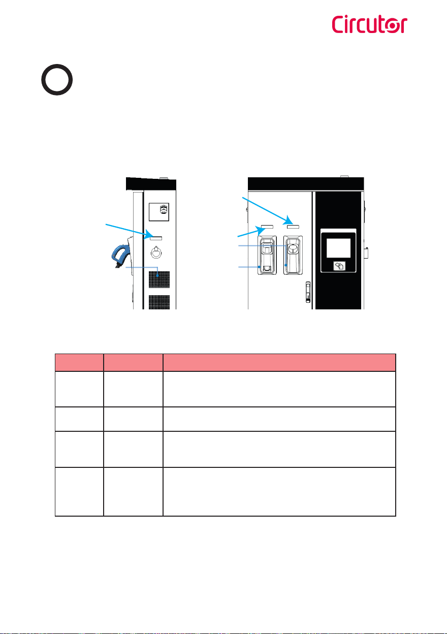
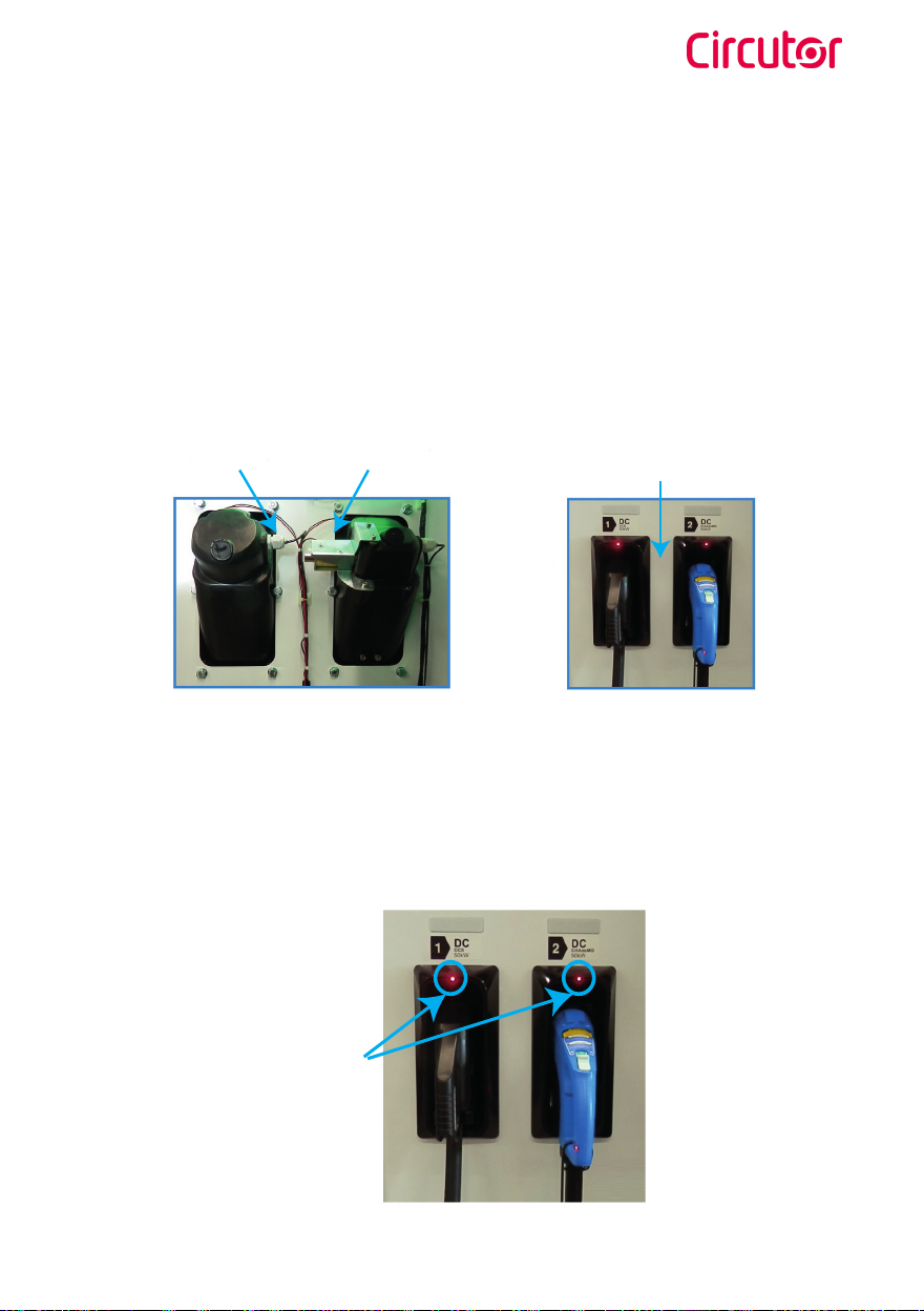
Position detector Locking coil Space for the
instruction label
Inside view Outside view
LEDs
Watch Out!!
If your Charge Point is equipped with the ‘Mechanical connector locking’ accesory
at DC holders, is not possible to pull back the connectors from holders without first
unlocking it.
There are one label placed between the CHAdeMO and the CCS holders explaining about
this function. Follow the instructions given in this label and the HMI screen.
Also, there is one Led over each holder indicating the lock state:
- Red > Connector locked
- Off > Connector unlocked

Raption 50
16 Instruction Manual
At the AC side for every Charge Point (It is not an optional device) there is a manual lock
for keeping the connector, follow the indications shown on the label in order to remove
the AC connector.
1- Push over the upper plastic button in order to release the connector.
2- Pull back the connector.
The connectors will be delivered right in the moment than the user push over the
‘Connector touching button’ when choose the option in the HMI screen:

Raption 50
17Instruction Manual
Raption 50
18 Instruction Manual
3
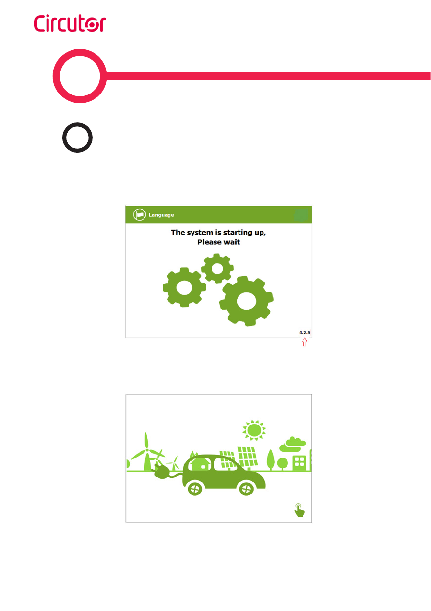
The first time the Charge Point is powered on, the system will take around 10 seconds
for starting up, the screen will show next image:
In the lower right corner, it shows the firmware version. After that 10 seconds have
passed, the first screen that appears is the screensaver,
Tap over this screen, and the HMI will skip to the next screen:
AGeneral

Raption 50
19Instruction Manual
How to use it ?
At this new screen, the Charge Point is asking for showing the identification card or
touch the screen, as you can see there are two options.
The first option, showing the identification card, is the option that will let to initiate a
‘Charging session’ to the user that has been registered in advance or has the identification
card.
The second option, touch the screen, is only to get information about the connectors
status and the charging process so as to know the Charge Point availability but you
cannot start or do any action over the currently charging session.
Also, at this screen and during all the process is possible to change language, pressing
on the top of the screen over the ‘Flag’ touch symbol:

Raption 50
20 Instruction Manual
Next screen will appear, press over your language’s flag:
It is possible to choose between next languages:
Catalan; German; English; Spanish; Finnish; French; Italian; Dutch; Norwegian; Polish;
Russian; Swedish; Arab; Icelandic.
Other manuals for Raption 50 Series
2
This manual suits for next models
8
Table of contents
Other Circutor Automobile Accessories manuals

Circutor
Circutor URBAN Series User manual

Circutor
Circutor Wallbox ePark Series User manual

Circutor
Circutor Wallbox eNext Series User manual

Circutor
Circutor Wallbox eNext Series User manual

Circutor
Circutor ePARK M-S2 User manual

Circutor
Circutor URBAN User manual

Circutor
Circutor URBAN WB DC Series User manual

Circutor
Circutor Raption 50 Series User manual

Circutor
Circutor Raption 150C Series User manual

Circutor
Circutor URBAN M11 User manual


