Circutor URBAN Series User manual

URBAN Series
INSTALLATION GUIDE
(M177A01-03-19A)

CIRCUTOR, SA reserves the right to make modifications to the device or the unit specifications
set out in this instruction manual without prior notice.
CIRCUTOR, SA on its web site, supplies its customers with the latest versions of the device
specifications and the most updated manuals.
www.circutor.com
Disclaimer
Revision log
Date Revision Description
06/17 M177A01-03-17A Initial Version
05/18 M177A01-03-18A Changes in the following sections:
2 - 2.A - 2.B - 4.E - 4.F
09/19 M177A01-03-19A Changes in the following sections:
2.- 2.B. -3. - 4.F. - 5.
2
URBAN
Installation Guide

Here’s your guide
to install URBAN.
Disclaimer ...................................................................................................................................................2
Revision log.................................................................................................................................................2
Here’s your guide to install URBAN.....................................................................................................3
1.-So,hello!...................................................................................................................................................4
2.-Before the installation...........................................................................................................................6
A. Minimum distances......................................................................................................................9
B. Foundation.....................................................................................................................................11
3.- Dimmensions and Overview.............................................................................................................12
4.-Installation............................................................................................................................................14
A. Opening...........................................................................................................................................14
B. Positioning......................................................................................................................................15
C. Fixation.............................................................................................................................................16
D. Metal plate.......................................................................................................................................17
E. Wiring...............................................................................................................................................18
F. Verification......................................................................................................................................19
5.- Technical Data ...................................................................................................................................20
Need help? ................................................................................................................................................23
Guarantee .................................................................................................................................................23
03Installation Guide
URBAN

1
04
URBAN
Installation Guide

So, hello!
This manual provides commissioning information, which has been designed
and tested to allow electric vehicle charging, specified in IEC 61851.
This document has dierent sections describing electrical components
inside the charge station and a step-by-step installation procedure.
ELECTRIC RISK
Take precautions to make the electrical connection inside the
unit.
Unit must be disconnected from any power source during
commissioning.
ATTENTION!
Indicates that the damage to property can occur if appropiate
precautions are not taken
THE FOLLOWING SYMBOLS ARE USED FOR IMPORTANT
SAFETY INFORMATION IN THIS DOCUMENT
• Complies with IEC 61851, Electric vehicle conductive charging
system (IES 61851-1 and IEC 61851-22)
• Complies with IEC 62196, Plugs, socket-outlets, vehicle couplers
and vehicle inlets (IEC 62196-1 and IEC 62196-2).
• Standards: 2014/35/UE, LVD;2014/30/UE, EMC.
• RFID complies with ISO 14443A/B
05Installation Guide
URBAN

The charge point is designed for installation in indoor and outdoor areas. For each of
the dierent conditions of installation, the unit must be installed safely and ensure
adequate protection.
• Charge point must not be installed
in areas where there is potential
risk of explosions.
• Do not install the charge point
where falling objects may damage
the equipment.
• The surface where the charge
point is placed must withstand the
mechanical forces.
• Do not use this unit for anything
other than electric vehicle charging
modes are expected in IEC 61851.
• Do not modify this unit. If
modified, CIRCUTOR will reject
all responsibility and the warranty
will be void.
• Comply strictly with electrical
safety regulations according to
your country.
• Do not make repairs or
manipulations with the unit
energised.
• Only trained and qualified
personnel should have access to
low-voltage electrical parts inside
the device.
• Check the installation annually by
qualified technician.
• Remove from service any item that
has a fault that could be dangerous
for users (broken plugs, caps that
don’t close...).
• Use only CIRCUTOR supplied
spare parts.
• Do not use this product if the
enclosure or the EV connector is
broken, cracked, open, or shows
any other indication of damage.
Refer to TECHNICAL DATA section for more information about environmental
installation conditions.
IMPORTANT SAFETY INSTRUCTIONS
Read carefully all the instructions before starting in
order to ensure properly installation of the charge
point.
2
06
URBAN
Installation Guide

ELECTRICAL WIRING CONSIDERATIONS
1 — ELECTRICAL PROTECTIONS
Charge point may not include elements of electrical protection.
If this equipment has internal electrical protections, are installed in each socket-outlet
for the protection of the user against an electrical failure, according to the international
standard IEC 61851-1:2017.
In order to guarantee the total protection of the users and the installation (power
supply line included) in front of any electrical hazard, it is mandatory to install a main
circuit breaker (MCB) and a residual current device (RCD) upstream of the charger.
These electrical protections and the rest of the installation have to be aligned with the
local and national rules. The selectivity of the protections has to be guaranteed at all
times.
2 — POWER SUPPLY LINE DIMENSIONING
The dimensioning of the input power supply line of the charge point must be checked
by a qualified electrician. Note that various factors such as cable length between
distribution board and charge point, maximum output current of the charge point may
have influence of the selected cable.
In such cases, increasing the cable cross-section it is required to adapt the temperature
resistance of the power supply line.
3 — MAXIMUM CURRENT OUTPUT
Please refer to the TECHNICAL DATA section to consult the default factory settings
from maximum output current of the charge point.
If the power supply is less than maximum output current and adjustment to a lower
nominal current needs to be performed, please refer to the INSTRUCTION MANUAL
(M177B01-03-xxx).
Depending of the model this value may vary.
Take into consideration this section before start wiring
connections of the charge point.
Before the
installation
07Installation Guide
URBAN

What’s included:
Charge Point Installation Guide CirCarLife RFID
Mifare Card
URBAN Post Key
Foundation Kit
Installation guide
08
URBAN
Installation Guide

AMinimum Distances
When installing the unit, respect the minimum distances space for maintenance and
safety reasons.
Please comply accordingly to your country specifications.
The next picture shows how it should be installed.
• Do not install near areas where water or fluids can penetrate into the unit.
• Do not install the unit in unstable terrain.
(1) If Bollard Impact Protector is installed, keep 500 mm as a minimum distance in
order to give enough space to open the frontal door of the charge point for maintance
tasks.
50
500
500
x
(1)
Measures in mm
09Installation Guide
URBAN

Foundation Kit:
Nuts
DIN 934 M16
Washers
DIN 9021 M16
Templates
Foundation bolts
16x
2x
4x
4x
10
URBAN
Installation Guide

BFoundation
• Place the foundation bolts into the template using provided nuts with the help of a
24mm open-end wrench.
• Once the kit is assembled, it must be placed in the ground taking into consideration the
following measures.
Note: In the event of any doubt about the terrain regarding the installation of this
unit, due to the weight and dimensions, it will be necessary to define a final solution
to install the unit. It must be confirmed by a specific technical project made for an
architectural firm prior to its installation.
250
119
230
320
220
130
400
450
300
500
300
Front view Side view
Measures in mm
11Installation Guide
URBAN

3
446
438
288
234
1544
1351
113
80
180
Measures in mm
12
URBAN
Installation Guide

Dimmensions
and Overview
12
6
3
4
5
(2) Sockets may vary depending on the model.
1
2
8
3
4
5
7
12
3
4
5
URBAN MASTER URBAN SLAVEURBAN M21 - T21 - M22
- T22 - T22-C - T24-MIX
1.- Hat 4.- Key lock access 7.- Touch screen
2.- LED Beacons 5.- Base 8.- RDIF Reader
3.- Socket (2) 6.- Display & RDIF Reader
13Installation Guide
URBAN

4
A
1 2
Opening
• Use provided key in order to open the unit (Key : type saw (EMKA EK333)):
14
URBAN
Installation Guide

Installation
BPositioning
1. Remove the template nuts before proceeding.
2. Place the charge point through the four foundation bolts.
15Installation Guide
URBAN

Firmly tighten the 4 nuts using a 24mm open-end wrench.
CFixation
16
URBAN
Installation Guide

• It is recommended to install a cable glands
(not supplied) in pre-holes position.
• Assembly metal plate using the 4 supplied
screws as shown below:
4x
DMetal plate
17Installation Guide
URBAN

Terminal block maximum cross-section: 35 mm2
Do not forget to connect the ground cable to the ground
terminal
Make sure all screws are securely tightened at 4...5 Nm
L L1
NL2
L3
N
EWiring
SINGLE-PHASE CHARGE POINT
• Connect to the 230V~.
THREE-PHASE CHARGE POINT
• Connect to the 400V~.
• If the Power Supply is Single-
Phase, connect L1 and N.
S
Note: The proper earthing system must be TT or TN-S. The ground loop impedance measurement for
the entire installation must be less than 80 ohms; however, it could be even less if required by national
regulations. At least once a year it is recommended to carry out the verification of the installation
grounding by qualified personnel when the terrain is drier
18
URBAN
Installation Guide

FVerification
1 — POWER INPUT
Before proceeding, make sure voltage is present in the terminal blocks.
2 — MAINTENANCE MODE
Pull outward the Tamper Switch located in the lower half of the Charge Point.
3 — CAREFUL WITH THE WIRES
When closing the unit, keep in mind all cables should remain inside.
4 — CHECK THE PLUGS
Plugs should be in good conditions before starting the unit.
5 — ELECTRICAL PROTECTIONS
Rearm all the protections installed on the unit.
6 — CHECK THE BEACON INDICATORS
All beacon indicators should light properly. Here’s the reference:
PLUG STATE BEACON COLOR
Available Green
Charging Blue
Fault Red
7 — OPERATION
Check no abnormal noise appears while the unit is charging.
For Three-Phase models pay special attention to Neutral Cable.
19Installation Guide
URBAN

5
ELECTRICAL DATA
URBAN MASTER - URBAN SLAVE
M2 T2 M2-C1 T2-C2
Power supply 1P+N+PE 3P+N+PE 1P+N+PE 3P+N+PE
Input voltage 230V~±10% 400V~±10% 230V~±10% 400V~±10%
Input current 32 A
Frequency 50Hz / 60Hz
Number of sockets 2
Maximum socket Power 7.4 kW 22 kW 7.4 kW 22 kW
Maximum Socket current 32 A
Connectors type Type 2 Socket Type 1 Cable Type 2 Cable
Charging Mode Mode 3
Min. cable cross-section(3) 25 mm2
Meter MID Class 1 - EN50470-3
Overcurrent protection MCB 40A (Curve C)
Safety protection RCD Type A (30 mA) / Type B (4)
Surge protection (4) Transient surge protector IEC 61643-1 (Class II)
URBAN M21, URBAN T21, URBAN M22, URBAN T22, URBAN T22-C, URBAN T24-MIX
M21 T21 M22 T22 T22-C T24-MIX
Power supply 1P+N+PE 3P+N+PE 1P+N+PE 3P+N+PE
Input voltage 230V~±10% 400V~±10% 230V~±10% 400V~±10%
Input Current 35 A 67 A
Frequency 50Hz / 60Hz
Number of
sockets 1 2 : Socket A, Socket B 4 (5) : 2 socket A,
2 socket B
Maximum
socket Power 7.4 kW 22 kW 7.4 kW
(socket A & B)
22 kW
(socket A & B)
22 kW / 3.7 kW
(socket A & B)
Maximum
socket
current
32 A 32 A (socket A & B) 32 A / 16 A
(socket A & B)
Connectors
type Type 2 Type 2 (socket A & B) Type 2 / CEE 7/3
(socket A & B)
20
URBAN
Installation Guide
Other manuals for URBAN Series
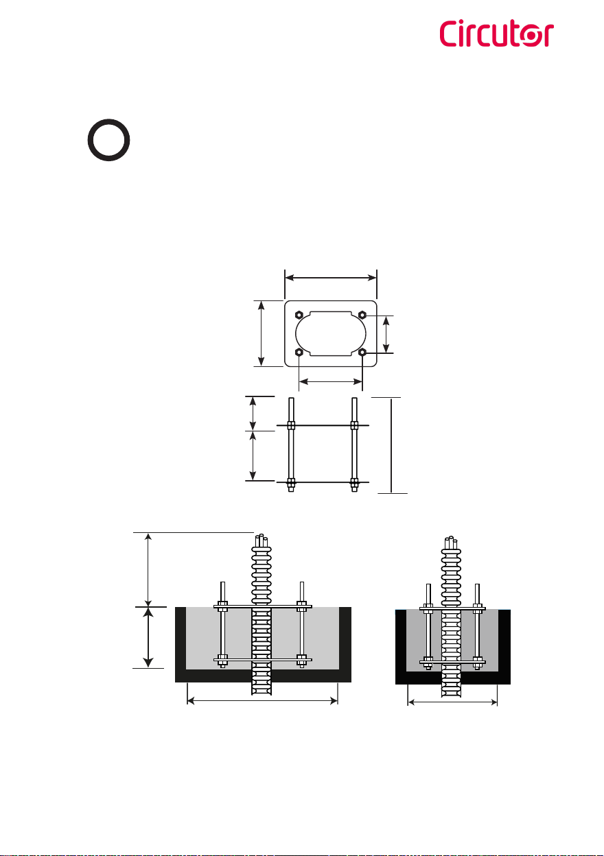
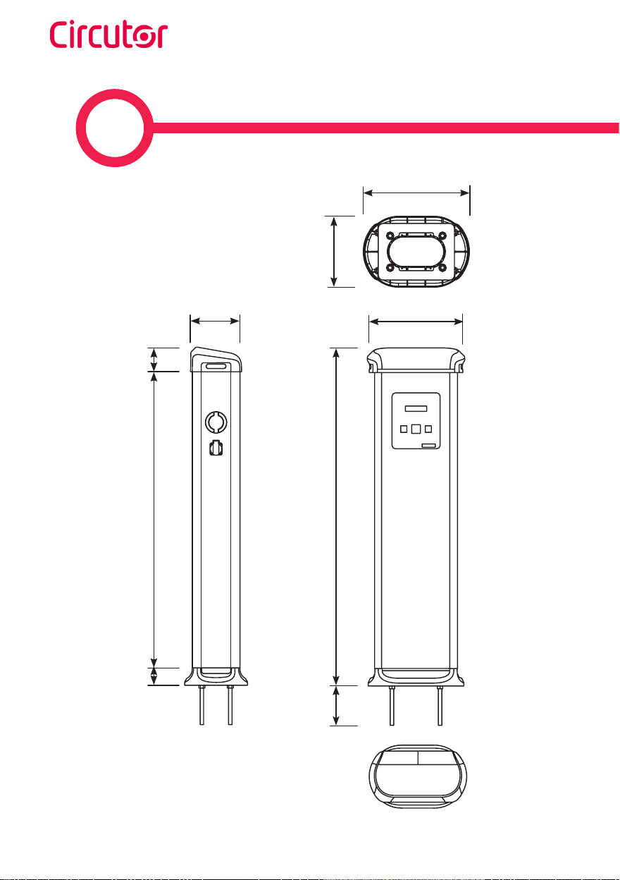
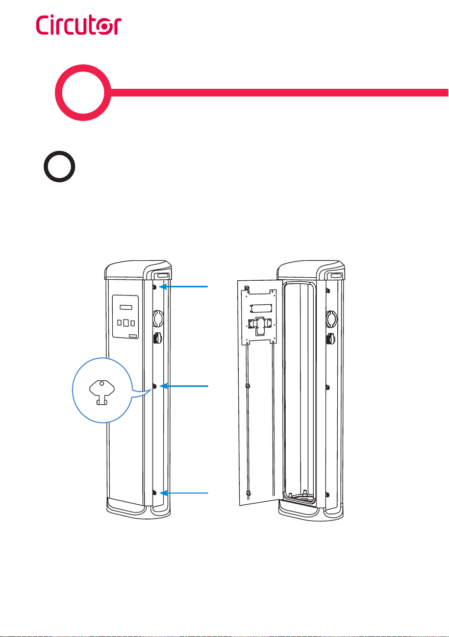
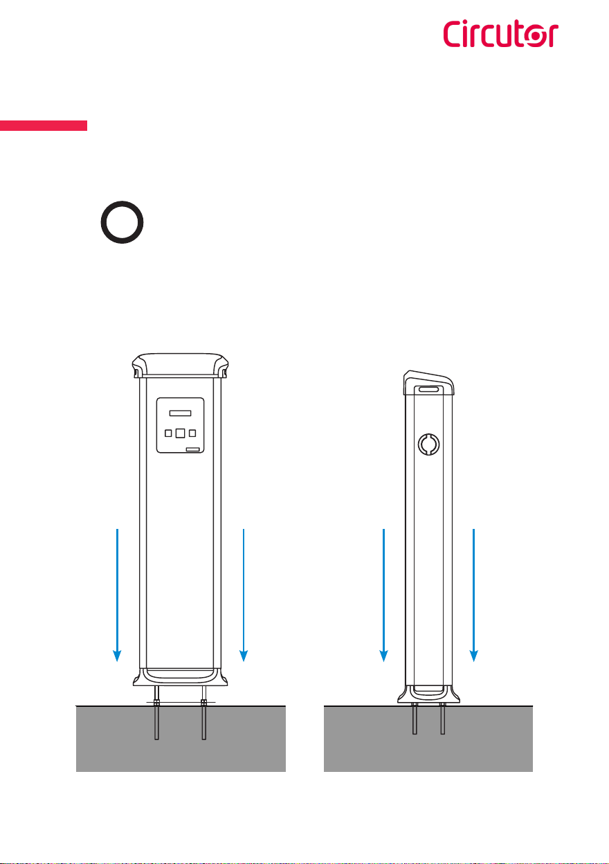
1
This manual suits for next models
14
Table of contents
Other Circutor Automobile Accessories manuals

Circutor
Circutor URBAN User manual

Circutor
Circutor Wallbox ePark Series User manual

Circutor
Circutor URBAN M11 User manual

Circutor
Circutor Wallbox eNext Series User manual

Circutor
Circutor Raption 50 Series User manual

Circutor
Circutor Raption 150C Series User manual

Circutor
Circutor URBAN WB DC Series User manual

Circutor
Circutor Raption Series User manual

Circutor
Circutor Raption 50 Series User manual

Circutor
Circutor Raption 50 HV User manual