Circutor Wallbox ePark Series User manual

Wallbox ePark
INSTALLATION GUIDE
(M262A01-03-19B)

Wallbox ePark
Installation guide
2
CIRCUTOR, SA reserves the right to make modifications to the device or the unit specifi-
cations set out in this instruction manual without prior notice.
CIRCUTOR, SA on its web site, supplies its customers with the latest versions of the de-
vice specifications and the most updated manuals.
www.circutor.com
Disclaimer
Revision log
Date Revision Description
06/19 M262A01-03-19A Initial Version
11/19 M262A01-03-19B
Changes in the following sections:
1. - 2.- 3. - 4. - 5. - 5.A. - 5.B. - 5.E. -
5.F. - 6.

Wallbox ePark
Installation guide 3
Wallbox ePark Series
Installation guide
COPYRIGHT INFORMATION
This document is copyrighted, 2019 by Circutor, S.A. All rights are reserved.
Circutor, S.A. reserves the right to make improvements to the products
described in this manual at any time without notice.
No part of this manual can be reproduced, copied, translated or transmitted in
any form or by any means without the prior written permission of the original
manufacturer. Information provided in this manual is intended to be accurate
and reliable. However, the original manufacturer assumes no responsibility for
its use, or for any infringements upon the rights of third parties at hat may result
from its use.
All other product names or trademarks are properties of their respective owners.

Wallbox ePark
Installation guide
4
Here’s your guide
to install ePark.
Disclaimer ....................................................................................................................................................2
Revision log...................................................................................................................................................2
Here’s your guide to install ePark...........................................................................................................4
1.-So,hello!....................................................................................................................................................5
2.-Before the installation...........................................................................................................................6
3.- Overview...................................................................................................................................................8
4.- Dimensions...........................................................................................................................................10
5.- Installation............................................................................................................................................12
A. Requirements.....................................................................................................................................13
B. Opening................................................................................................................................................14
C. Positioning...........................................................................................................................................15
D. Fixing....................................................................................................................................................16
E. Wiring....................................................................................................................................................17
F. Closing...................................................................................................................................................19
6.- Technical Data......................................................................................................................................22
Need help?................................................................................................................. .................................25
Guarantee....................................................................................................................................................25
Wallbox ePark
Installation guide 5
1So, hello!
This manual provides commissioning information about Wallbox ePark, which
has been designed and tested to allow electric vehicle charging, specified in
IEC 61851.
This document has dierent sections such as step-by-step installation
procedure and technical data.
ELECTRIC RISK
Necessary precautions shall be taken to prevent any electrical
risk while the operations are carried out within the unit.
Unit must be disconnected from any power source during
commissioning.
ATTENTION!
Indicates that the damage to property can occur if appropriate
precautions are not taken
THE FOLLOWING SYMBOLS ARE USED FOR IMPORTANT
SAFETY INFORMATION IN THIS DOCUMENT
• Complies with IEC 61851, Electric vehicle conductive charging
system (IEC 61851-1 and IEC 61851-22).
• Complies with IEC 62196, Plugs, socket-outlets, vehicle
couplers and vehicle inlets (IEC 62196-1 and IEC 62196-2).
• Standards: 2014/35/UE, LVD;2014/30/UE, EMC.
• RFID complies with ISO 14443A/B
Wallbox ePark
Installation guide
6
The charge point is designed for installation in indoor and outdoor areas. For each of the
dierent conditions of installation, the unit must be installed safely and ensure adequate
protection.
• Charge point must not be installed
in areas where there is potential
risk of explosions.
• Do not install the charge point
where falling objects may damage
the equipment.
• The surface where the charge
point is placed must withstand the
mechanical forces.
• This unit is no shall be used for
anything other purpose than
electric vehicle charging modes as
are expected in IEC 61851..
• Do not modify this unit. If
modified, CIRCUTOR will reject all
responsibility and the warranty will
be void.
• Comply strictly with electrical
safety regulations according to your
country.
• Do not use any adapter, except those
approved by the EV manufacturer.
• Do not perform any repair o
manipulation of the unit while it is
energized.
• Only trained and qualified personnel
should have access to low-voltage
electrical parts inside the unit.
• Check the installation annually by
qualified technician.
• Remove from service any item that
has a fault that could be dangerous
for users (broken plugs, caps that
don’t close...).
• Use only CIRCUTOR supplied spare
parts.
• Do not use this product if the
enclosure or the EV connector is
broken, cracked, open, or shows any
other indication of damage.
Refer to TECHNICAL DATA section for more information about environmental
installation conditions.
IMPORTANT SAFETY INSTRUCTIONS
Read carefully all the instructions before starting in
order to ensure properly installation of the charge
point.
2
Wallbox ePark
Installation guide 7
ELECTRICAL WIRING CONSIDERATIONS
Take into consideration this section before start wiring
connections of the charge point.
Before the
installation
1 — ELECTRICAL PROTECTIONS
Charge point may not include elements of electrical protection.
If this equipment has internal electrical protections, are installed in each socket-outlet
for the protection of the user against an electrical failure, according to the international
standard IEC 61851-1.
In order to guarantee the total protection of the users and the installation (power supply
line included) in front of any electrical hazard, it is mandatory to install a main circuit
breaker (MCB) and a residual current device (RCD) upstream of the charger.
These electrical protections and the rest of the installation have to be aligned with the
local and national rules. The selectivity of the protections has to be guaranteed at all
times.
2 — POWER SUPPLY LINE DIMENSIONING
The dimensioning of the input power supply line of the charge point must be checked by a
qualified electrician. Note that various factors such as cable length between distribution
board and charge point, maximum output current of the charge point may have influence
of the selected cable.
In such cases, increasing the cable cross-section it is required to adapt the temperature
resistance of the power supply line.
3 — MAXIMUM OUTPUT CURRENT
Please refer to the TECHNICAL DATA section to consult the default factory settings from
maximum output current of the charge point.
If the power supply is less than maximum output current and adjustment to a lower
nominal current needs to be performed.
Depending of the model this value may vary.

Wallbox ePark
Installation guide
8
3
What’s included:
Charge Point Installation
Guide
Installation Guide
2.5 mm
Allen wrench
Wallbox ePark
Installation guide 9
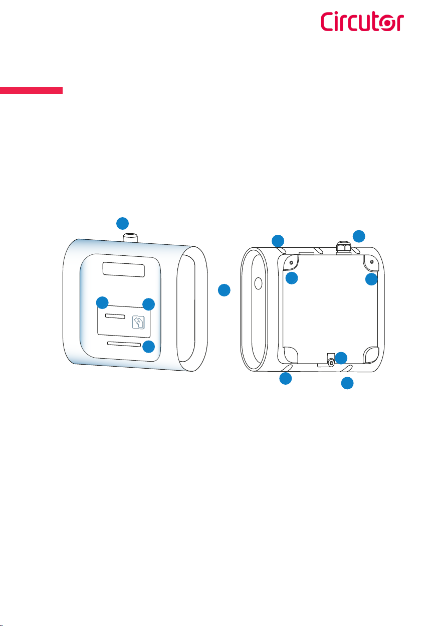
Overview
1 — LED beacon
2 — Cable glands
3 — Plugs
4 — Wall support holes
5 — Closing box holes
6 — LCD
7 — RFID reader
1
2
3
52
4
4
4
5
7
6
5

Wallbox ePark
Installation guide
10
4
Measures in mm
335 315
200
335
39

Wallbox ePark
Installation guide 11
Dimensions
168
105
62.5
52.5
20 (1)
39.5
255
20.5
62.5 52.5
34 34
230
(1) This measurement may vary.

Wallbox ePark
Installation guide
12
5
Material:
Tap drill 6/8M
Tools:
Screw driver Driller
Ratchet(2)
2.5mm Allen
• Allen wrench of 2,5 mm is included in the installation kit.
• Screws, sealing washers and plastic anchors are not included.
• The fastening system of the Charge Point has been designed to be
installed on a wall.
»This system has been tested on a concrete wall, to be securely fixed in
such conditions is recommended to use:
3 x Inox A2 wall screws: DIN 7982 Ø4,8x3
3 x plastic anchors: 6x40 or 8x40
»If the wall surface has dierent properties, the screws and plastic
anchors must be defined by a qualified installer.
(2) Ratchet tool can be used to open/close the Charge Point if required by the conditions of installa-
tion.

Wallbox ePark
Installation guide 13
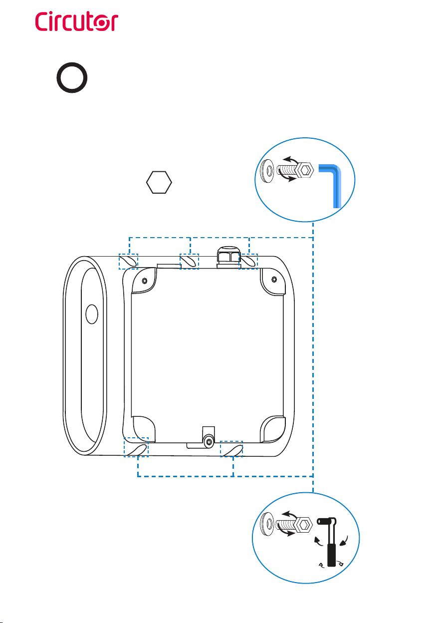
Installation
ARequirements
Dimensions in mm
300
1100
300
300
• Please comply with your country regulations.
• The Charge Point shall be installed on a wall or on CIRCUTOR accessories.
• When installing the unit, some space shall be reserved for usability, maintenance
and safety reasons. The picture below shows the recommended minimum
distances:
If the recommendations are not followed as described,
CIRCUTOR will reject all responsibility and the warranty
will be void.
Wallbox ePark
Installation guide
14
BOpening
Open the Wallbox using allen wrench.
2.5mm Allen wrench
Use the ratchet tool to open/close
the change point wall fixed

Wallbox ePark
Installation guide 15
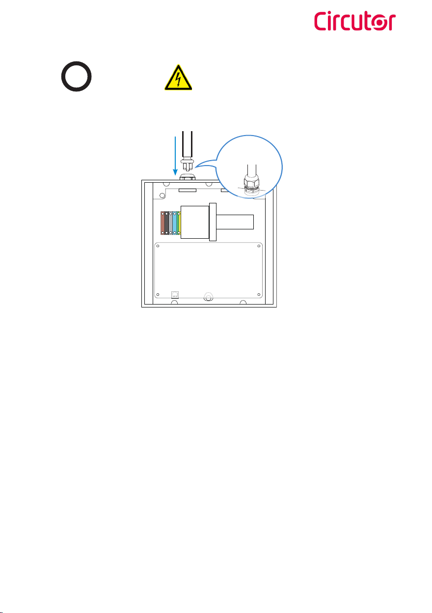
CPositioning
Drill the wall.
Drill bit M 6/8
Measures in mm
1100
255
230
115
Remove PCB plastic support to connect the ethernet and put the screw into the wall.
RJ45 Wall
Screw
PCB plastic support
methacrylate
screws

Wallbox ePark
Installation guide
16
DFixing
Place de unit on the previously leaky points and fix it by the screws
Wallbox ePark
Installation guide 17
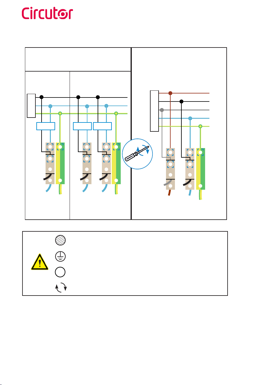
EWiring
A A
B
Cable
glands M32
Use provided cable glands in order to mantain the IP protection
• The IEC-61851-1 ed 3 standard indicates that each plug shall have protections. In case the
Charge Point has no protections inside, they shall be upstreams. It is recommended that these
protections be as follows:
°RCD: Residual current device. Standards: IEC 61008-1, IEC 61009-1,IEC 60947-2 or IEC
62423.
°RCD(s) rated residual operating current not exceeding 30 mA.
°For AC fault current, RCD(s) protecting that connecting points shall be at least type A.
°RCD(s) shall disconnect all live conductors.
°DC fault current shall be mesured by a RCD type B or a appropriate equipment that ensures
the disconnection of the supply in case of DC fault current above 6 mA.
°MCB(s): Miniature circuit breaker. Standards: IEC 60898-1, IEC 60947-2 or IEC 61009-1.
°MCB(s) minimun breaking capacity 4 kA.
• The current of the power supply can be limited. In order to perform this adjustment please refer
to the Instruction Manual.
Wallbox ePark
Installation guide
18
SINGLE-PHASE CHARGE POINT
• Connect to the 230V~.
THREE-PHASE CHARGE POINT
• Connect to the 400V~.
• If the Power Supply is Single-Phase,
connect L1 and N.
Do not forget to connect the ground cable to the ground terminal
Terminal block maximum cross-section: 10 mm2
Make sure all screws are securely tightened at 4...5 Nm
S
Note: The proper earthing system must be TT or TN-S. The ground loop impedance measurement
for the entire installation must be less than 80 ohms; however, it could be even less if required
by national regulations. At least once a year it is recommended to carry out the verification of the
installation grounding by qualified personnel when the terrain is drier.
Type of cable allowed by the terminal block: Copper
L1
L2
L3
N
PE
L
LA L B
NA NB
N
Protections
A
Protections Protections
B
TWO
CONNECTORS ONE
CONNECTORS
PE
Cu

Wallbox ePark
Installation guide 19
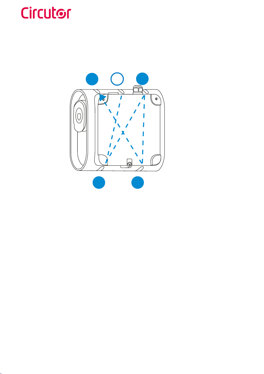
FClosing
PLUG STATE
Available
Charging
Fault
BEACON COLOR
Green
Blue
Red
Close the Charge Point as per the following steps of verification and operation.
1 — POWER INPUT
Before proceeding, make sure voltage is present in the terminal blocks.
For Three-Phase models pay special attention to Neutral Cable.
2 — CAREFUL WITH THE WIRES
Before closing the unit, keep in mind that all cables should remain inside.
3 — CHECK THE PLUGS
Plugs should be in good condition before starting the unit.
4 — ELECTRICAL PROTECTIONS
If the unit includes electrical protections, rearm all of them.
5 — CLOSING
Place the sealing washers on the screws and then place both in the Charge Point to close it. Do
not thight the screws yet.
6 — CHECK THE BEACON LIGHTS
All beacon lights should light properly. Here’s the reference:
7 — OPERATION
Check that no abnormal noise appears while the unit is charging.
Wallbox ePark
Installation guide
20
8 — SECURE CLOSURE
• Tighten the screws crosswise in the sequence shown below.
• As a guideline, the recommended assembly torque is 0.8-1Nm.
9 — OPERATION
Check that no abnormal noise appears while the unit is charging.
10 — PREVENTIVE MAINTENANCE
It is recommended to perform one preventive maintenance per year.
1
5
2
3
4
This manual suits for next models
5
Table of contents
Other Circutor Automobile Accessories manuals

Circutor
Circutor URBAN WB DC Series User manual

Circutor
Circutor Raption 50 Series User manual

Circutor
Circutor Raption 150 Series User manual

Circutor
Circutor URBAN User manual

Circutor
Circutor URBAN Series User manual

Circutor
Circutor Wallbox eNext Series User manual

Circutor
Circutor Raption 150 Series User manual

Circutor
Circutor Raption 150C Series User manual

Circutor
Circutor URBAN M11 User manual

Circutor
Circutor Raption 50 HV User manual


