Circutor Wallbox eNext Series User manual

Wallbox eNext Series
INSTALLATION GUIDE
(M255A01-03-20A)

Wallbox eNext
Installation guide
2
CIRCUTOR, SA reserves the right to make modifications to the device or the unit specifi-
cations set out in this instruction manual without prior notice.
CIRCUTOR, SA on its web site, supplies its customers with the latest versions of the de-
vice specifications and the most updated manuals.
www.circutor.com
Disclaimer
Revision log
Date Revision Description
05/19 M255A01-03-19A Initial Version
11/19 M255A01-03-19B
Changes in the following sections:
1.- 2.- 3.- 4. - 5.- 5.A. - 5.B.- 5.C. -
5.E. - 5.F. - 5.G. - 5.H. - 5.I. - 5.J. - 6.
02/20 M255A01-03-20A Changes in the following sections:
6.

Wallbox eNext
Installation guide 3
Wallbox eNext Series
Installation guide
COPYRIGHT INFORMATION
This document is copyrighted, 2019 by Circutor, S.A. All rights are reserved.
Circutor, S.A. reserves the right to make improvements to the products
described in this manual at any time without notice.
No part of this manual can be reproduced, copied, translated or transmitted in
any form or by any means without the prior written permission of the original
manufacturer. Information provided in this manual is intended to be accurate
and reliable. However, the original manufacturer assumes no responsibility for
its use, or for any infringements upon the rights of third parties at hat may result
from its use.
All other product names or trademarks are properties of their respective owners.

Wallbox eNext
Installation guide
4

Wallbox eNext
Installation guide 5
Here’s your guide
to install eNext.
Disclaimer ....................................................................................................................................................2
Revision log...................................................................................................................................................2
Here’s your guide to install eNext...........................................................................................................5
1.-So,hello!....................................................................................................................................................6
2.-Before the installation...........................................................................................................................8
3.- Overview................................................................................................................................................12
4.- Dimensions...........................................................................................................................................14
5.- Installation............................................................................................................................................16
A. Requirements....................................................................................................................................17
B. Opening................................................................................................................................................18
C. Positioning..........................................................................................................................................19
D. Fixing....................................................................................................................................................20
E. Wiring...................................................................................................................................................21
F. CirBEON................................................................................................................................................23
G. DC current leakage detector..........................................................................................................24
H. Welded contactor detector.............................................................................................................24
I. Remote control function...................................................................................................................25
J. Closing .................................................................................................................................................26
6.- Technical Data.....................................................................................................................................28
Need help?..................................................................................................................................................31
Guarantee....................................................................................................................................................31

Wallbox eNext
Installation guide
6
1
Wallbox eNext
Installation guide 7
This manual provides commissioning information about Wallbox eNext, which
has been designed and tested to allow electric vehicle charging, specified in
IEC 61851.
This document has dierent sections such as step-by-step installation
procedure and technical data.
ELECTRIC RISK
Necessary precautions shall be taken to prevent any electrical
risk while the operations are carried out within the unit.
Unit must be disconnected from any power source during
commissioning.
ATTENTION!
Indicates that the damage to property can occur if appropriate
precautions are not taken
So, hello!
THE FOLLOWING SYMBOLS ARE USED FOR IMPORTANT
SAFETY INFORMATION IN THIS DOCUMENT
• Complies with IEC 61851, Electric vehicle conductive charging
system (IEC 61851-1:2017).
• Complies with IEC 62196, Plugs, socket-outlets, vehicle
couplers and vehicle inlets (IEC 62196-1 and IEC 62196-2).
• Standards: 2014/35/UE, LVD;2014/30/UE, EMC.

Wallbox eNext
Installation guide
8
A safe work environment is not enough to control all potential electrical hazards. It is
recommended to be very cautious and work safely. So, the safety rules shown below
could help to control risks of injury or death from workplace hazards.
• Avoid contact with energized
electrical circuits.
• Disconnect the power source before
servicing or repairing electrical
equipment. The only way to be sure.
• Use only tools and equipment with
non-conducting handles when
working on electrical devices.
Easier to check.
• Never use metallic pencils or rulers,
or wear rings or metal watchbands
when working with electrical
equipment. This rule is very easy
to forget, especially when you
are showing some electrical part
pointing with metallic pencil.
• Enclose all electric contacts and
conductors so that no one can
accidentally come into contact.
• When it is necessary to handle
equipment that is plugged in, be
sure hands are dry and, when
possible, wear nonconductive
gloves, protective clothes and shoes
with insulated soles.
• If it is safe to do so, work with only
one hand, keeping the other hand
at your side or in your pocket, away
from all conductive material. This
precaution reduces the likelihood
of accidents that result in current
passing through the chest cavity.
• Never handle electrical equipment
when hands, feet, or body are wet
or perspiring, or when standing on
a wet floor.
IMPORTANT ELECTRICAL SAFETY INSTRUCTIONS
Read carefully all the instructions before starting in
order to ensure properly handling of electrical parts.
2
Wallbox eNext
Installation guide 9
Before the
installation
The charge point is designed for installation in indoor and outdoor areas. For each of the
dierent conditions of installation, the unit must be installed safely and ensure adequate
protection.
• Charge point must not be installed
in areas where there is potential
risk of explosions.
• Do not install the charge point
where falling objects may damage
the equipment.
• The surface where the charge
point is placed must withstand the
mechanical forces.
• This unit is no shall be used for
anything other purpose than
electric vehicle charging modes as
are expected in IEC 61851.
• Do not modify this unit. If
modified, CIRCUTOR will reject all
responsibility and the warranty will
be void.
• Comply strictly with electrical
safety regulations according to your
country.
• Do not use any adapter, except those
approved by the EV manufacturer.
• Do not make repairs or
manipulations with the unit
energised.
• Only trained and qualified personnel
should have access to low-voltage
electrical parts inside the unit.
• Check the installation annually by
qualified technician.
• Remove from service any item that
has a fault that could be dangerous
for users (broken plugs, caps that
don’t close...).
• Use only CIRCUTOR supplied spare
parts.
• Do not use this product if the
enclosure or the EV connector is
broken, cracked, open, or shows any
other indication of damage.
Refer to TECHNICAL DATA section for more information about environmental
installation conditions.
IMPORTANT CHARGE POINT SAFETY INSTRUCTIONS
Read carefully all the instructions before starting in
order to ensure properly installation of the charge
point.
Wallbox eNext
Installation guide
10
ELECTRICAL WIRING CONSIDERATIONS
Take into consideration this section before starting
wiring connections of the charge point.
1 — ELECTRICAL PROTECTIONS
Charge point may not include elements of electrical protection.
If this equipment has internal electrical protections, are installed in each socket-outlet
for the protection of the user against an electrical failure, according to the international
standard IEC 61851-1:2017.
In order to guarantee the total protection of the users and the installation (power supply
line included) in front of any electrical hazard, it is mandatory to install a main circuit
breaker (MCB) and a residual current device (RCD) upstream of the charger.
These electrical protections and the rest of the installation have to be aligned with the
local and national rules. The selectivity of the protections has to be guaranteed at all
times.
2 — POWER SUPPLY LINE DIMENSIONING
The dimensioning of the input power supply line of the Charge Point must be checked by a
qualified electrician. Note that several factors such as cable length between distribution
board and Charge Point, maximum output current of the Charge Point may influence the
criteria of cable selection.
In such cases, increasing the cable cross-section it is required to adapt the temperature
resistance of the power supply line.
3 — MAXIMUM OUTPUT CURRENT
Please refer to the TECHNICAL DATA section to consult the default factory settings from
maximum output current of the charge point.
If the power supply is less than maximum output current and adjustment to a lower
nominal current needs to be performed, please refer to the INSTRUCTION MANUAL.
This value may vary depending on the model.

Wallbox eNext
Installation guide 11
Wallbox eNext
Installation guide
12
3
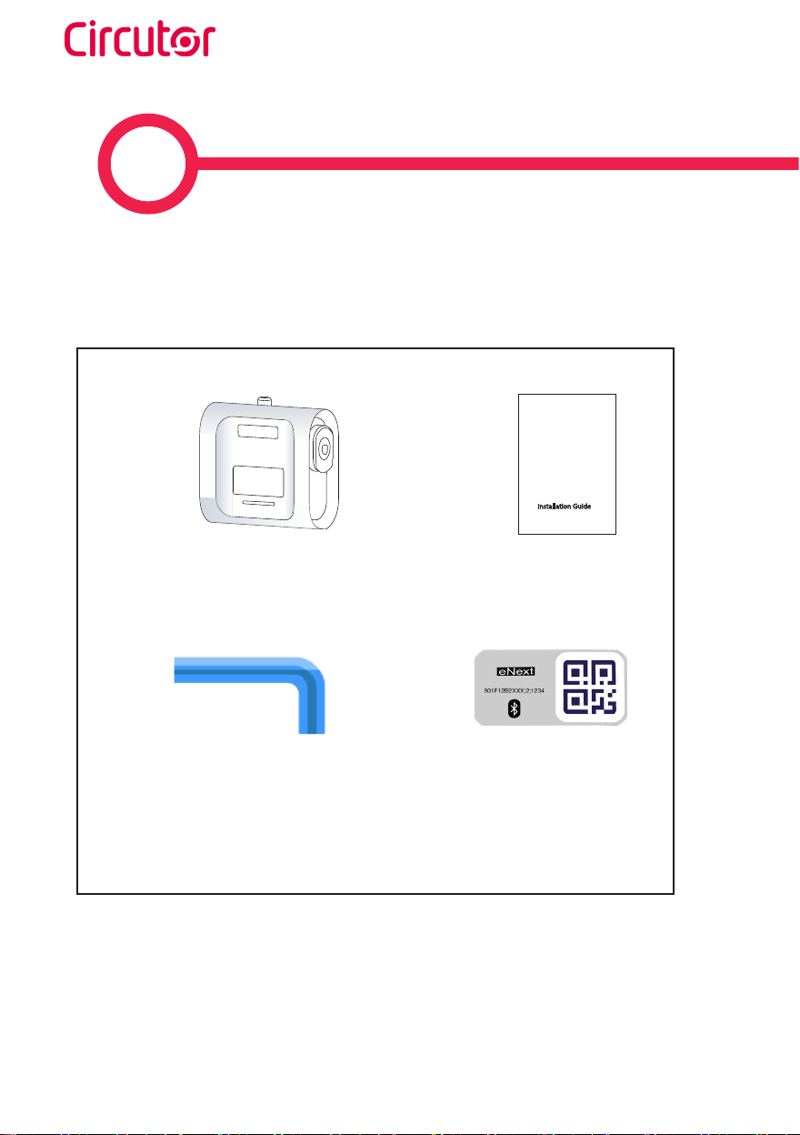
What’s included:
Charge Point Installation
Guide
Installation Guide
2.5 mm
Allen wrench Identification
label
Wallbox eNext
Installation guide 13
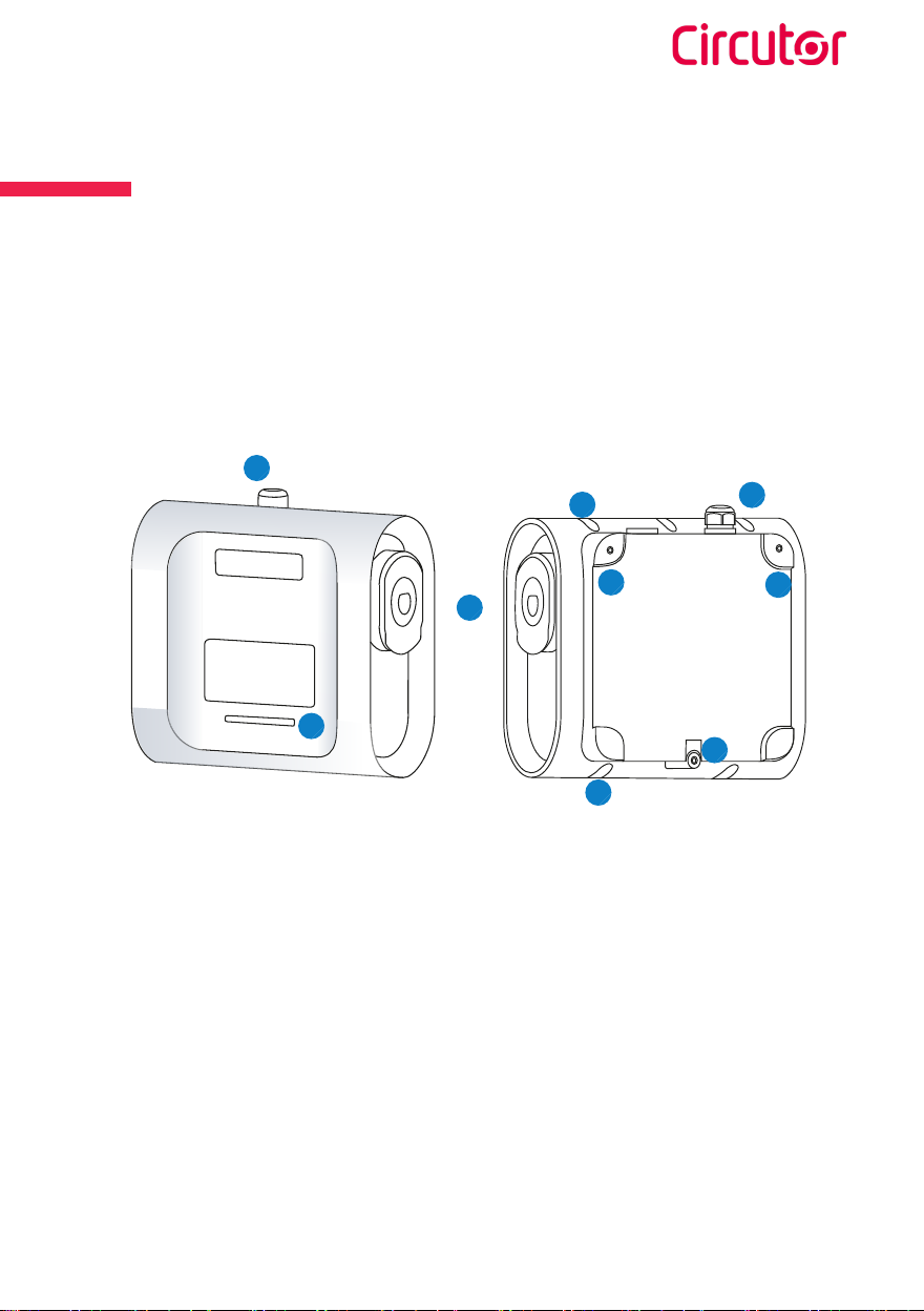
Overview
1 — Beacon lights
2 — Cable glands
3 — Plugs(1)
4 — Wall support holes
5 — Closing box holes
(1) Plugs may vary depending on the model
1
2
3
52
4
4
4
5
Wallbox eNext
Installation guide
14
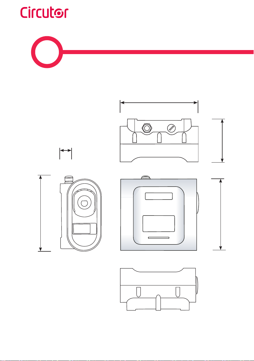
4
Measures in mm
39
335 315
200
335

Wallbox eNext
Installation guide 15
Dimensions
168
105
62.5
52.5
20 (2)
39.5
255
20.5
62.5 52.5
34 34
230
(2) This measurement may vary.

Wallbox eNext
Installation guide
16
5
Material:
Tap drill 6/8M
Tools:
• Allen wrench of 2,5 mm is included in the installation kit.
• Screws, sealing washers and plastic anchors are not included.
• The fastening system of the Charge Point has been designed to be
installed on a wall.
»This system has been tested on a concrete wall, to be securely fixed in
such conditions is recommended to use:
3 x Inox A2 wall screws: DIN 7982 Ø4,8x3
3 x plastic anchors: 6x40 or 8x40
»If the wall surface has dierent properties, the screws and plastic
anchors must be defined by a qualified installer.
Screw driver Driller
Ratchet(3)
2.5mm Allen
(3) Ratchet tool can be used to open/close the charge point if the conditions of the installation
requiers it
Wallbox eNext
Installation guide 17
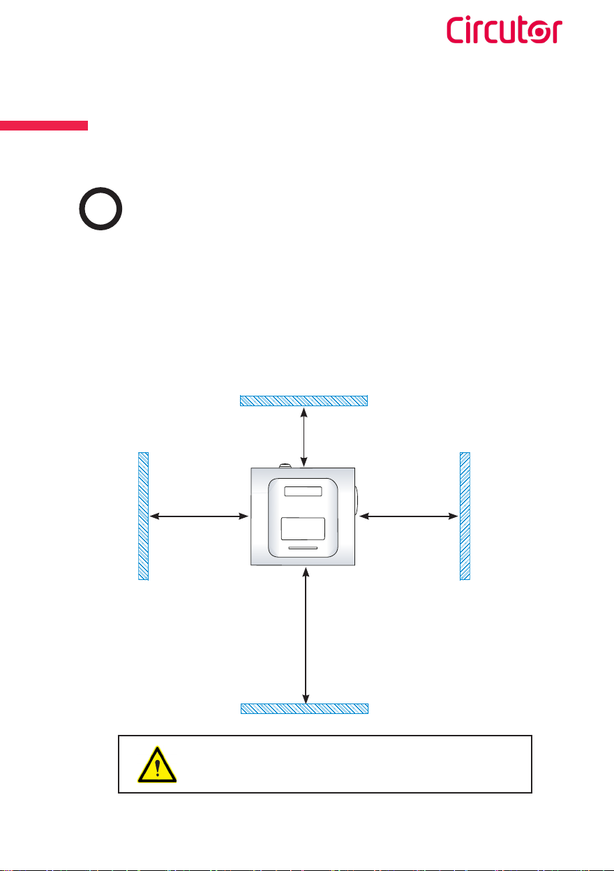
Installation
ARequirements
Dimensions in mm
300
1100
300
300
• Please comply with your country regulations.
• The Charge Point shall be installed on a wall or on CIRCUTOR accessories.
• When installing the unit, some space shall be reserved for usability, maintenance
and safety reasons. The picture below shows the recommended minimum
distances:
If the recommendations are not followed as described,
CIRCUTOR will reject all responsibility and the warranty
will be void.
Wallbox eNext
Installation guide
18
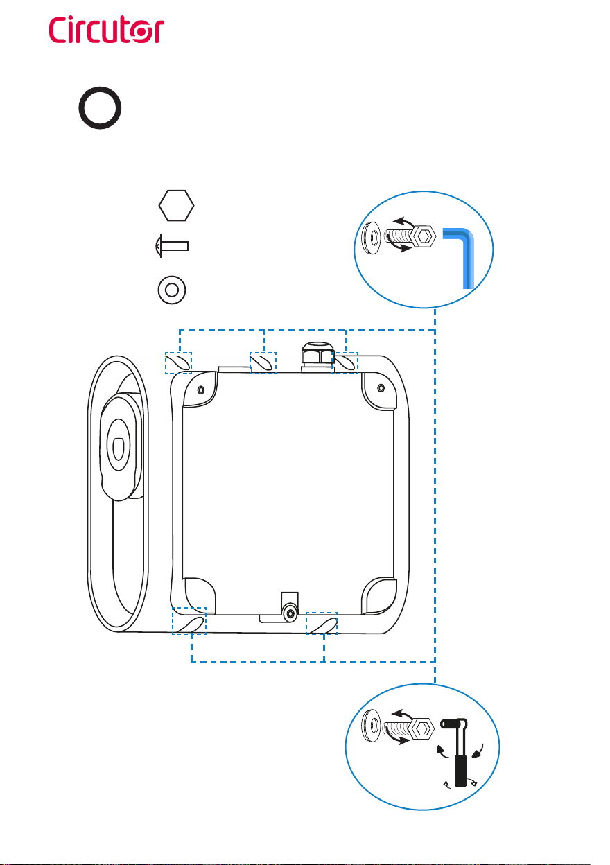
BOpening
Open the Wallbox using allen wrench.
2.5mm Allen wrench
Use the ratchet tool to open/close
at dicult access case
Screw
DIN-7380-2 M4x14 INOX
Sealing washer
DIN 7712 4.8 14MM INOX

Wallbox eNext
Installation guide 19
CPositioning
Make the holes.
Tap drill M 6/8
Dimensions in mm
1100
255
230
115

Wallbox eNext
Installation guide
20
DFixing
Place the unit on the previous pierced points and fix it with screws.
Other manuals for Wallbox eNext Series
2
This manual suits for next models
4
Table of contents
Other Circutor Automobile Accessories manuals

Circutor
Circutor URBAN WB DC Series User manual

Circutor
Circutor ePARK M-S2 User manual

Circutor
Circutor Raption Series User manual

Circutor
Circutor Raption 50 Series User manual

Circutor
Circutor Wallbox ePark Series User manual

Circutor
Circutor Raption 150C Series User manual

Circutor
Circutor URBAN M11 User manual

Circutor
Circutor URBAN User manual

Circutor
Circutor Raption 150 Series User manual

Circutor
Circutor Raption 50 Series User manual


