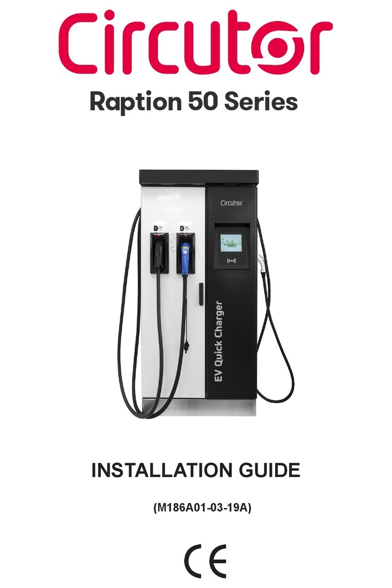
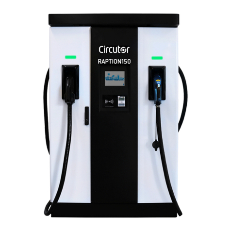
Circutor Raption 150 Series User manual

Raption 150 Series
SERVICE MANUAL
(M291C01-03-21A)

Raption 150
2Service Manual

Service Manual 3
Raption 150
Raption 150 Series
Service Manual
COPYRIGHT INFORMATION
This document is copyrighted, 2021 by CIRCUTOR, S.A. All rights are reserved.
CIRCUTOR, S.A. reserves the right to make improvements to the products described in
this manual at any time without notice.
No part of this manual can be reproduced, copied, translated or transmitted in any form
or by any means without the prior written permission of the original manufacturer.
Information provided in this manual is intended to be accurate and reliable. However,
the original manufacturer assumes no responsibility for its use, or for any infringements
upon the rights of third parties that may result from its use.
All other product names or trademarks are properties of their respective owners.

Raption 150
4Service Manual
Revision log
Date Revision Description
05/21 M291C01-03-21A Initial Version
Disclaimer
CIRCUTOR, SA
reserves the right to make modifications to the device or the unit specifications set
out in this instruction manual without prior notice.
CIRCUTOR, SA on its web site, supplies its customers with the latest versions of the device specifica-
tions and the most updated manuals.
www.circutor.com

Service Manual 5
Raption 150
Contents
Disclaimer .................................................................................................................................................4
Revision log ..............................................................................................................................................4
Contents ...................................................................................................................................................5
1.- So, hello!..............................................................................................................................................8
2.- Features ............................................................................................................................................10
A. Main features .............................................................................................................................10
B. Dimensions...................................................................................................................................12
C. Components Overview.................................................................................................................14
3.- Control devices.................................................................................................................................28
A.- PC Screen (HMI)........................................................................................................................28
B.- Mode 4 Board............................................................................................................................ 31
C.- CCS Board ..................................................................................................................................34
D.- Distributor board.......................................................................................................................36
E.-Supervisor board........................................................................................................................37
F.-Nodes boards..............................................................................................................................38
G.- Relays boards ..........................................................................................................................40
4.- Protection devices............................................................................................................................42
A.- Disconnector..............................................................................................................................42
B.- RCD .............................................................................................................................................44
C.- MCCBs ........................................................................................................................................45
D.- MCBs...........................................................................................................................................46
E.-RCBOs...........................................................................................................................................47
F.- Backflow diode and Clixon.......................................................................................................48
G.-Transient surge protector.........................................................................................................50
H.- Isolation protection device.......................................................................................................51
5.- Other components...........................................................................................................................54
A.- Heater system............................................................................................................................54
B.-Ventilation system.....................................................................................................................55
C.-RFID reader..................................................................................................................................56
D.- AC meter......................................................................................................................................57
E.-Power supplies...........................................................................................................................58
F.- UPS..............................................................................................................................................59
G.- Output Fuses.............................................................................................................................60
H.- Output Contactors .................................................................................................................. 62
I.- Teltonika RUT 240......................................................................................................................64
6.- Other optional components ..........................................................................................................66
A.- RFID Reader - Legic................................................................................................................. 66
B.- Payment terminal.................................................................................................................... 68
7.-Troubleshooting & Errors.................................................................................................................70
A.-Troubleshooting introduction..................................................................................................70
B.- Log files .....................................................................................................................................74

Raption 150
6Service Manual
C.- Decoding the error.....................................................................................................................76
D.- Error code in remote.................................................................................................................84
E.- Communication errors..............................................................................................................86
F.-OCPPErrors..................................................................................................................................87
G.- Power modules errors..............................................................................................................93
8.- Maintenance ................................................................................................................................... 94
9.- Annexes.............................................................................................................................................96
10.-Technical Data ................................................................................................................................98
Need help ? ..........................................................................................................................................101
Guarantee .............................................................................................................................................101

Service Manual 7
Raption 150

Raption 150
8Service Manual
This manual provides service and maintenance information for CIRCUTOR Charge Point,
which has been designed and tested to allow electric vehicle charging, specified in IEC
61851.
This document has different sections describing electrical components inside the Charge
Point and a step-by-step installation procedure.
It is mandatory to follow the basic security information supplied in this manual to ensure
safe and proper installation.
Failure to follow safety instructions may involve personal injury, equipment damage and
danger of death. CIRCUTOR is not responsible for events arising from such breach.
ELECTRIC RISK
-This symbol indicates a potentially hazardous situation which, if not avoided
may result in a risk of fire, serious injury or death.
- The Charge Point must be disconnected from any power source before
performing any maintenance, repair or electrical manipulation inside.
ATTENTION!
- Follow the instructions preceded by this symbol, if not respect them or
perform them correctly, may result in minor or moderate injury to the user,
damage to equipment, damage to facilities or other property.
- Handling the equipment can cause injuries as result of the dimension and
weight. Persons handling the unit must wear safety shoes and gloves.
1
THE FOLLOWING SYMBOLS ARE USED FOR IMPORTANT
SAFETY INFORMATION IN THIS DOCUMENT

Service Manual 9
Raption 150
So, hello!
Read carefully all the instructions before doing any
maintenance work inside the Charge Point.
Important safety instructions
• Read all the instructions before using
and configuring the Charge Point.
• Do not use the Charge Point for anything
other than electric vehicle charging
modes are expected in IEC 61851.
• Do not modify the Charge Point. If
modified, CIRCUTOR will reject all
responsibility and the warranty will be
void.
• Comply strictly with electrical safety
regulations according to your country.
• Do not make repairs or manipulations
with the unit energized.
• Only trained and qualified personnel
should have access to the electrical parts
inside the Charge Point.
• Check the installation annually by
qualified technician.
• Remove from service any item that has
a fault that could be dangerous for users
(broken connectors, caps that don’t
close...).
• Use only CIRCUTOR supplied spare parts.
• Do not use this product if the enclosure
or the EV connector is broken, cracked,
open, or shows any other indication of
damage.
• Adaptors or conversion adapters and
cord extensions set are NOT allowed to
be used.

Raption 150
10 Service Manual
2
AMain features
DISPENSER
Note: Depending of the model, the components can vary.
1
5
4
6
8
7
3
10
9
11
2
12
1.- Cover 2.- Courtesy Lights 3.- Screen 4.- CCS/CHA plug
5.- Emergency button 6.- RFID Reader 7.- Locking handle 8.- Decorative Front panel
9.- Antenna 10.- CCS/CHA cables 11.- LED beacons Light 12.-Front Door

Service Manual 11
Raption 150
Features
POWER UNIT
3
7
8
4
1
2
5
10
9
6
1.- Cover 2.- Unit air inlet 3.- Locking handle 4.- Locking handle
5.- Rear door 6.- Decorative Rear panel 7.- Eyebolts 8.- Unit air outlet
9.- Front door 10.- Decorative Front panel

Raption 150
12 Service Manual
BDimensions
Units specified in millimeters:
DISPENSER
300
380
470
2070

Service Manual 13
Raption 150
Units specified in millimeters:
POWER UNIT
2150
800
2100
1000

Raption 150
14 Service Manual
Components Overview
C
Control part
Dispenser
door
DISPENSER
Connection and
proteccion part
Dispenser can be divided in three different parts. The opening door, the control part and
the connection and protection part.

Service Manual 15
Raption 150
Relays
boards Control side
Output wiring to
Dispenser
Power
modules
Block B
POWER UNIT
PU power
input supply
Power
modules
Block A
Power
modules
Block A
Power
modules
Block B
Power
modules
protections
Power Unit has two doors, in the front and in the rear side. When it is opened from the
front, power input supply and protections can be found. When opening from the rear
side, there is the control part and the output connectors. Power modules can be checked
from both sides, specially from the front one.

Raption 150
16 Service Manual
1 — DISPENSER DOOR
1
2
36
5
4
1.- Teltonika RUT240 2.- HMI touch screen 3.- Contactless terminal
4.- Switch 5P 5.- Connector terminals 6.- RFID Reader

Service Manual 17
Raption 150
2 — CONTROL PART
1
2
4
3
5
7
8
9
10
6
1.- Output contactors 2.- Output signal filter for CCS
3.- Isolation protector for CCS 4.- Lock system for CCS cable
5.- Mode 4 board for CCS 6.- CCS communications board Reader
7.- Output signal filter for CHA 8.- Isolation protector for CHA
9.- Mode 4 board for CHA 10.- Tamper interruptor

Raption 150
18 Service Manual
3 — CONNECTION AND PROTECTION PART
1
2
3
4
5
6
7
8
9
10
11
12
1.- Power supply 24 Vdc 2.- Connectors terminals
3.- EMI filter 4.- AC input supply connection
5.- CCS circuit disconnector 6.- Power supply 12 Vdc
7.- UPS 8.- Distribuitor board
9.- Service schuko 10.- Dispenser MCBs
11.- CHA Fuse 10.- CHA circuit disconnector

Service Manual 19
Raption 150
4 — POWER MODULES BLOCK A AND B
1- Power module 12.5kW (A8.1-A8.6)
2- Power module 12.5kW (A9.1-A9.6)

Raption 150
20 Service Manual
5 — PU POWER INPUT SUPPLY
2
1
3
5
4
6
1.- RCBO (Q05.3) 2.- Service Schuko 3.- Overvoltage protection
4.- Busbars 5.- Fuses (F05.1, F05.2, F05.3) 6.- Power input supply
Other manuals for Raption 150 Series
2
Table of contents
Other Circutor Automobile Accessories manuals

Circutor
Circutor Raption 150 Series User manual
Circutor
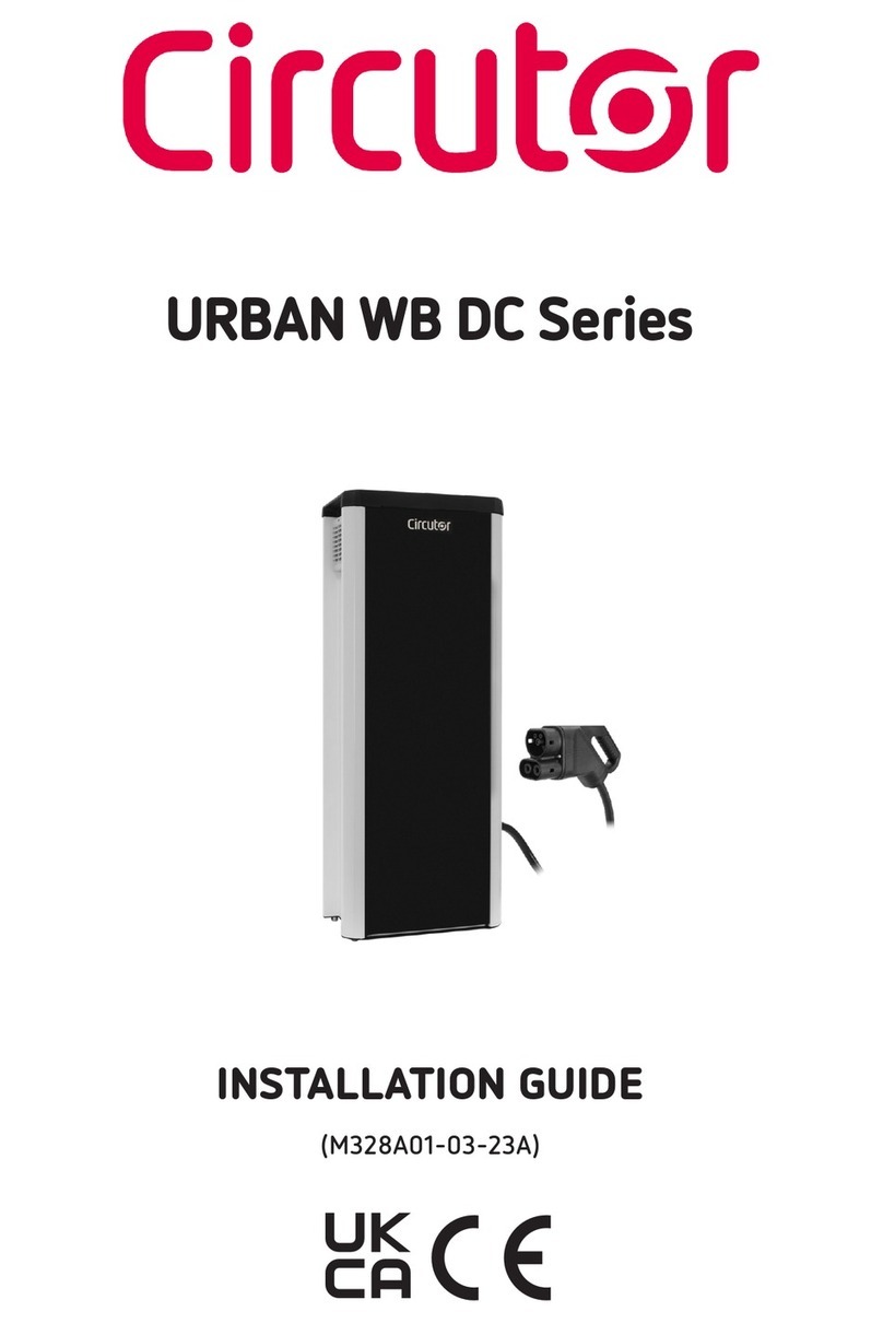
Circutor URBAN WB DC Series User manual

Circutor
Circutor Wallbox eNext Series User manual

Circutor
Circutor URBAN M11 User manual
Circutor
Circutor Raption 150C Series User manual

Circutor
Circutor ePARK M-S2 User manual

Circutor
Circutor Raption 50 HV User manual

Circutor
Circutor Wallbox ePark Series User manual
Circutor
Circutor Raption Series User manual
Circutor
Circutor URBAN Series User manual

