Cirs 715 User manual
Pediatric Anthropomorphic
Training Phantoms
USER GUIDE
Model 715
900 Asbury Ave • Norfolk, Virginia 23513 • USA • Tel: 757-855-2765 • WWW.CIRSINC.COM

OBJECTIVE
An ideal addition to any imaging department or Radiologic Technology training
program, the CIRS Model 715 Series can assist in the monitoring, training and
improvement of parameters and protocols common to most pediatric imaging
procedures.
SPoRTTM is designed to aid teaching and improvement of patient positioning, col-
limation and anatomical comprehension and it’s wide range of features facilitate
effective instruction of safe, high quality, pediatric imaging.
SPoRTTM can be used in film radiography, CR, DR and Computed Tomography.
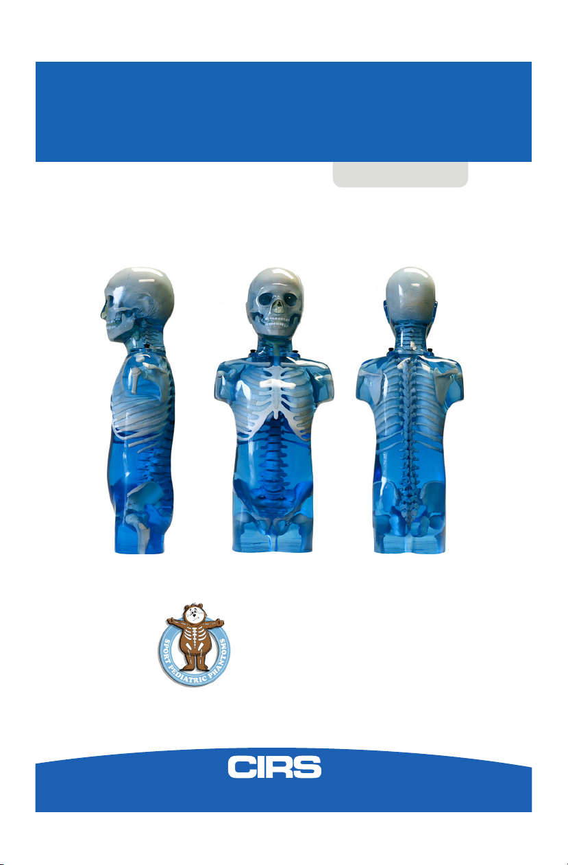
DESCRIPTION OF THE PHANTOM
The phantom represents a typical 5-year old in both size and structure, making it
portable and easy to position. The full body with head, arms and legs measures
110 cm (43 inches) tall and weighs 20 kg (44 lb).
Right extremeties are available in extended or flexed configurations. Left arm and
leg are available with or without embedded fractures. The fracture versions contain
the most common pediatric fracture types, including buckle fracture to tibia and
common fracture to fibula; fracture to first metatarsal; radius fracture with open
reduction and hardware and a common fracture to second intermediate phalange.
Components are made from propriety urethane and epoxy materials that mimic
X-ray attenuation properties of human tissues for both diagnostic and therapy
energy ranges (50keV-15MeV). The materials are durable, impact resistant and suit-
able for continuous handling.
The Model 715 series consists of six sectional phantoms available separately or as
a complete set. Complete set includes head, trunk, right and left arms with natural
and oblique hand positions and right and left legs with natural and plantar flexion
foot positions.

SPECIFICATIONS AND OPTIONAL ACCESSORIES
MODEL DESCRIPTION
9508 Optional custom carry case for entire 715 (not including optional large positioning stand).
715-S-1 Optional large positioning stand for head, torso and appendages. Includes positioning stand, "HEAD" and "TRUNK" base/ quick-release plates, (2)
long thumb screws, (2) short thumb screws, (4) unattached quick-release plates, and allen wrench.
038-20 SRS Frame Support Cups, Set of 4 (compatible with 715-HN)
PART NO. DESCRIPTION INCLUDES WEIGHT DIMENSIONS
715-HN
Head
Skull, Homogeneous Brain, Sinus, Cavities, Ear Canals, C1-C7 Spine, Spinal Disks, Deciduous
and Descending Teeth with enamel and dentin, Small positioning stand for use with head only
2.75 kg 21 cm H x 14 cm W
x 17 cm D
715-T
Trunk
Chest, Rib Cage, Spine, Spinal Disks, Lungs, Bronchial Tree to third bifurcation, Lung Vascula-
ture, Trachea, Scapula, Clavicles, Top Third of Humerus, Pelvis,
Top Third of
Femur
9.85 kg 44.5 cm H x 24 cm
W x 14 cm D
715-A-R
Right Arm
Elbow in natural position, Full bone structure, Oblique hand position 0.7 kg 37 cm L x 8 cm W x
7cm D
715-A-
R-90
Right Arm
Flexed 90
Degrees
Elbow flexed 90 degrees, Full bone structure, Oblique hand position 0.7 kg
32 cm L x 8 cm W
x 13 cm D
715-A-L
Left Arm
Elbow in natural position, Full bone structure, Natural hand position 0.7 kg 37 cm L x 9 cm W
x 5 cm D
715-A-
L-FX
Left Arm with
Fractures
Elbow in natural position, Full bone structure, Natural hand position, R
adius fracture with open
reduction and hardware, Common fracture to second intermediate phalange
0.7 kg 37 cm L x 9 cm W
x 5 cm D
715-L-R
Right Leg
Knee in natural position, Full bone structure, Relaxed foot position 2.50 kg 42.5 cm L x 9 cm W
x 18 cm D
715-L-R-
90
Right Leg
Flexed 90
Degrees
Knee flexed 90 degrees, Full bone structure, Relaxed foot position 2.50 kg
34 cm Lx 9 cm W x
19 cm D
715-L-L
Left Leg
Knee in natural position, Full bone structure, Plantar foot flexion 2.50 kg
51.5 cm L x 9 cm W x
18 cm D
715-L-
L-FX
Left Leg with
Fractures
Knee in natural position, Full bone structure, Plantar foot flexion
Buckle fracture to tibia and
common fracture to fibula; Fracture to first metatarsal
2.50 kg
51.5 cm L x 9 cm W x
18 cm D

SOFT TISSUE
ENERGY- MEV REF. MUSCLE CIRS RATIO, %
0.04 0.2804 0.2548 90.87
0.06 0.2146 0.2121 98.84
0.08 0.1913 0.1940 101.41
0.10 0.1777 0.1822 102.53
0.20 0.1426 0.1478 103.65
0.40 0.1104 0.1147 103.89
0.60 0.0932 0.0969 103.97
0.80 0.0818 0.0851 104.03
1.00 0.0736 0.0765 103.94
2.00 0.0514 0.0534 103.89
4.00 0.0354 0.0365 103.11
6.00 0.0288 0.0295 102.43
8.00 0.0252 0.0256 101.59
10.0 0.0230 0.0233 101.30
20.0 0.0188 0.0185 98.40
30.0 0.0177 0.0171 96.61
El. Density, x1023, cm-3 3.621 3.616 99.86
Density, gcm-3 1.10 1.103 -
USE OF THE PHANTOM
The phantom should be used as a training aid for positioning techniques, colloma-
tion, and anatomical comprehension. Simply scan phantom using the same x-ray
technical factors as would be used on a lean patient.
Each user of the phantom may find additional uses and CIRS urges one to share
findings with others when possible and appropriate.
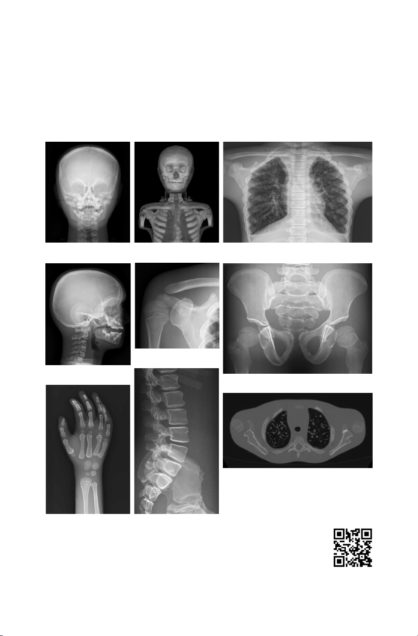
Lateral Skull
3D Reconstruction
Lateral Lumbar Spine
AP Skull AP Chest
AP Pelvis
AP Shoulder
Oblique Hand/Wrist
CT
To download the phantom DICOM data set (Resources) or view the
multimedia gallery, visit: www.cirsinc.com/products/all/36
SOFT TISSUE
POSITIONING STANDS
The Model 715 can be used with two positioning stands: a small positioning stand
included and only for use with the head phantom (Model 715-HN), and an optional
large stand (Model 715-S-1) which can be used with all of the components of the
Model 715. These stands are designed to allow users to practice alignment and
positioning for different x-ray views.
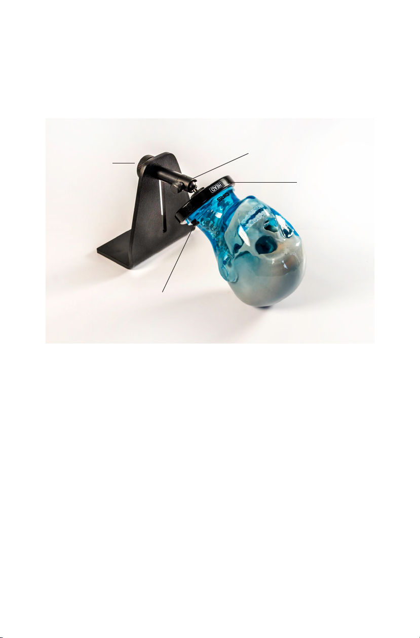
SMALL POSITIONING STAND
The Small Positioning Stand (Figure 1) should be fully assembled when you receive
your phantom. The only additional setup required will be to attach the phantom
head to the "HEAD" base plate for positioning.
1. Remove the thumb screws from the "HEAD" base plate.
2. Position the phantom face up and align raised cylinder on the phantom with
the matching cavity on the "HEAD" base plate.
3. Tighten the thumb screws to secure the phantom head to the small positioning
stand and base plate.
To adjust the height of the socket base, turn the large hand wheel on the frame
bracket 1/2 turn counter-clockwise, slide socket base to desired height and secure
position by turning large hand wheel 1/2 turn clockwise. Use the small hand wheel
on socket base to adjust the angle and rotation of the head and neck in relation to
the x-ray couch. For greater stability while using the phantom on stand, use a heavy
object as counterweight.
Figure 1
Thumb Screws
Large Hand Wheel
Small Hand Wheel
"HEAD" Base Plate
LARGE POSITIONING STAND (MODEL 715-S-1)
The optional Large Positioning Stand (Figure 2), can be used with any of SPoRT's
sections. The stand includes unattached quick-release plates for appendages and
combination base/quick-release plates for the head and trunk sections, along with
necessary tools and hardware to attach plates to all SPoRT sections. These plates
must be attached to the section before the section may be positioned using the
Large Positioning Stand.
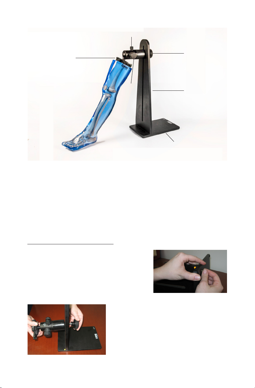
Assembling Large Positioning Stand
To assemble frame bracket, lay positioning
stand base along the long edge and align
with the upright so that orange stickers
face toward each other. Ensuring that
edges of base and upright are flush, insert
provided screws and tighten with screw
driver. Be sure not to over tighten.
To attach socket base to frame bracket,
unscrew the large hand wheel from socket
base. Slide large hand wheel through frame
bracket and reattach to socket base. This
completes large positioning assembly.
Figure 2 (Tension Knob on Socket Base not shown)
Figure 4
Figure 3
Large Hand Wheel
on Frame Bracket
Upright
Quick-Release Plate
Small Hand Wheel on Socket Base
Base
Locking
knob on
Socket
Base
WARNING: Phantom may fall off table causing injury to operator. Before securing
SPoRT sections on the Large Positioning Stand, place a heavy object on the base
of the stand as a counterweight.
Attaching Prepared SPoRT Section to Large Positioning Stand
All prepared sections attach to the Large Positioning Stand by locking the quick-
release plate to the pre-assembled positioning stand mount on the Large Position-
ing Stand socket base. To lock the quick-release plate into the positioning stand
mount:
1. Unlock the locking lever on the positioning stand mount. Lever will be in 12
o'clock position when unlocked as shown in Figure 6.
2. Orient the section so anterior surface is facing ceiling.
3. Tilt section so quick-release plate is angled to allow posterior edge to make
first contact with posterior edge on the mount.
4. Rotate section to allow entire surface of quick-release plate to make contact
with positioning stand mount. The locking lever will automatically flip to locked
position as shown in Figure 7.
Figure 6 Figure 7
Preparing SPoRT Sections for attachment to Large Positioning Stand
Head & Trunk sections attach to the
Large Positioning Stand using a
combination base/quick-release plate.
This plate must be secured on the
respective section using included thumb
screws. Longer thumb screws are used
on the trunk section. Shorter thumb
screws are used on the head section.
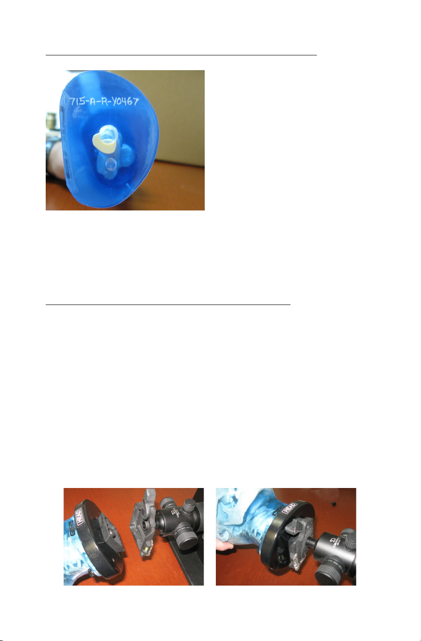
Arm & leg sections attach to the Large
Positioning Stand using a quick-release
plate. This plate must be secured on
the respective section using included
screws. Align the holes in the quick-
release plate with the pre-drilled holes
located on the superior end of each
section (Figure 5). Insert screws and
tighten with included allen wrench.
Figure 5

Using Large Positioning Stand to adjust SPoRT Section Positions
The Large Positioning Stand consists of a frame bracket and socket base. The
large hand wheel on the back of the frame bracket is used to secure the height of
the socket base on the frame bracket. To adjust the height of the socket base,
turn this large hand wheel 1/2 turn counter-clockwise, slide socket base to desired
height and secure position by turning large hand wheel 1/2 turn clockwise.
The angle and rotation of the attached SPoRT section is controlled by adjusting the
ball-joint within the socket base. The three hand wheels on the socket base control
this ball-joint.
• The small hand wheel locks the rotation of the entire socket base. Loosen 1/4
turn to adjust rotation.
• The tension knob is a tension knob used to add friction while adjusting the
phantom positioning. Keep this knob tight for well-controlled movement.
• The locking knob will lock/ loosen the ball in the socket. By loosening this
wheel, you will be able to adjust the rotation and the angle of the phantom in
the positioning stand.
CARE AND HANDLING
Solicit help when moving an assembled head and trunk phantom as it may be
heavy and become hazardous if dropped.
The phantom should be stored in a safe place when not in use. The phantom may
be cleaned with mild soap and water.
Technical questions should be referred to CIRS customer service at
(800) 617-1177.

WARRANTY
All standard CIRS products and accessories are warranted by CIRS against defects
in material and workmanship for a period as specified below. During the warranty
period, the manufacturer will repair or, at its option, replace, at no charge, a product
containing such defect provided it is returned, transportation prepaid, to the manu-
facturer. Products repaired in warranty will be returned transportation prepaid.
There are no warranties, expressed or implied, including without limitation any im-
plied warranty of merchantability or fitness, which extend beyond the description on
the face hereof. This expressed warranty excludes coverage of, and does not pro-
vide relief for, incidental or consequential damages of any kind or nature, including
but not limited to loss of use, loss of sales or inconvenience. The exclusive remedy
of the purchaser is limited to repair, recalibration, or replacement of the product at
manufacturer’s option.
This warranty does not apply if the product, as determined by the manufacturer,
is defective because of normal wear, accident, misuse, or modification.
NON-WARRANTY SERVICE
If repairs or replacement not covered by this warranty are required, a repair estimate
will be submitted for approval before proceeding with said repair or replacement.
RETURNS
If you are not satisfied with your purchase for any reason, please contact your local
distributor prior to returning the product. Visit https://www.cirsinc.com/distributors/
to find your local distributor. If you purchased your product direct through CIRS, call
Customer Service at 800-617-1177, email [email protected], or fax an RMA request
form to 757-857-0523. CIRS staff will attempt to remedy the issue via phone or
email as soon as possible. If unable to correct the problem, a return material
authorization (RMA) number will be issued. Non-standard or “customized” products
may not be returned for refund or exchange unless such product is deemed by
CIRS not to comply with documented order specifications. You must return the
product to CIRS within 30 calendar days of the issuance of the RMA. All returns
should be packed in the original cases and or packaging and must include any
accessories, manuals and documentation that shipped with the product. The RMA
number must be clearly indicated on the outside of each returned package. CIRS
recommends that you use a carrier that offers shipment tracking for all returns and
insure the full value of your package so that you are completely protected if the
shipment is lost or damaged in transit. If you choose not to use a carrier that offers
tracking or insure the product, you will be responsible for any loss or damage to the
product during shipping. CIRS will not be responsible for lost or damaged return
shipments. Return freight and insurance is to be pre-paid.
WITH RMA NUMBER, ITEMS MAY BE RETURNED TO:
CIRS
Receiving
900 Asbury Ave,
Norfolk, Virginia, 23513 USA
PRODUCT WARRANTY PERIOD
Model 715 Series - Sectional Pediatric Anthropomorphic
Training Phantom 60 Months


©
2013 Computerized Imaging Reference Systems, Inc. All rights reserved.
Specifications subject to change without notice.
Publication: 715 UG 072220
Computerized Imaging Reference Systems, Inc. has been
certified by UL DQS Inc. to (ISO) 13485:2016. Certificate
Registration No.10000905-MP2016.
COMPUTERIZED IMAGING
REFERENCE SYSTEMS, INC.
900 Asbury Ave
Norfolk, Virginia 23513 USA
Toll Free: 800.617.1177
Tel: 757.855.2765
Fax: 757.857.0523
Email [email protected]
www.cirsinc.com
Technical Assistance
1.800.617.1177
Table of contents
Other Cirs Medical Equipment manuals


