Cirs MRIdian Phantom User manual
Motion Phantom for MRI Automatic
Tracking and Gating
USER GUIDE

1
Table of Content
Overview…………………………………………………………………...2
Description of Phantom…………………………………….…………...2
Specifications …….……………………………………………………....3
Use of Phantom…………………………………………………………...4
A. Unpacking Instructions …………..…………………………4
B. Assembly Instructions ….…….…..…………………………8
C. Oscilloscope Connection….…….....………………………13
D. Repacking Instructions …………..………………...………17
Care and Handling………………………………………….................19
Warranty………..…………………………………………....................20

Overview
The phantom is to be used to validate the capability of Viewray®
system to track and deliver a gated treatment based on MRI real
time imaging. Dosimetry capabilities of the phantom enhance the
validation of the whole Viewray system from the planning phase
to the final stage of gated treatment delivery. This phantom was
designed in collaboration with Viewray and complies with
Viewray Requirements Specification document RQ-0034 Rev C.
Refer to Viewray protocol FTP-06 Rev B “Functional Test
Procedure” for detailed instructions regarding how to use this
phantom with the MRIdian system.
*Viewray® is a registered trademark (Oakwood Village, OH)
Description of the Phantom
The phantom consists of the following
subassemblies/components:
-Custom Linear actuator (modified CIRS model 008A Linear
actuator as required by input of project 796-01-00).
-Cross bars (front and back) for Actuator indexing to Viewray
system treatment couch.
-Custom Motion Controller box (modified CIRS model 008A
Motion Controller as required by input of project 796-01-00 –
modified firmware) –includes standard 008A communication
cables (USB over Ethernet communication Controller-PC).
-MRI signal generating Body with static non-deformable targets
and rigid organs at risk. Ion chamber (Exradin A28)**
dosimetry enabled for all targets and OARs. **Other ion chambers
are available. Refer to CIRS cavity codes at www.cirsinc.com/support for
corresponding CV number.
-MRI signal generating Moving Rod with one dosimetry non-
deformable target and non-dosimetry and non-deformable
targets.
-Supports (front and back) to index MRI Body to Viewray
system treatment couch. Supports allows Viewray Torso Coils
placement around the MRI Body.
-Connector shafts between Actuator –MRI Body
-Shipping cases 2

3
- Accessories
NOTE: The MRI signal generating Body does not include
any ferrous or metallic parts except for the ¼-20 – 1”
long Brass screws used to fasten the couch indexing pegs
to the MRI Body supports. These Brass screws were
selected accordingly with Viewray input for model 008V.
The closest ferrous or metallic parts to the MRI signal
generating Body are the ones from the Custom Linear
actuator.
MRI signal generating Body
Dimensions: Ø254mm x 236mm (Gel Volume ~Ø229.3mm x 220mm)
Weight: ≈30 lb.
Materials: Body Housing –Acrylic;
Body and Body targets –CIRS proprietary gels
MRI signal generating Moving Rod
Dimensions: Ø63mm x 290mm ((Gel Volume ~Ø57mm x 254mm)
Weight: ≈4 lb.
Materials: Rod Housing –Acrylic;
Rod and Rod target –CIRS proprietary gels
Specifications

4
Use of the Phantom
A. Unpacking Instructions
Before you open the case check the three Drop ‘N’ Tell
indicators on the right side of the case. (Drop ‘N’ Tell
shipping damage indicator shows when a case has been
dropped in transit and contains potential damaged goods.
The sensor displays a red arrow when applied before
shipping. If the container receives a shock exceeding 25 G
force, the sensor display arrows will change to blue. If the
sensor has been activated and is blue, a claim may need to
be filed with the carrier. If activated, take extra care in
inspecting the components as they are unpacked, assembled
and tested. Note: If there is any damage to the packaging
case, containers, foam, and components, or operation,
immediately contact the carrier and the phantom
supplier, and keep all packaging for carrier inspection.)
5
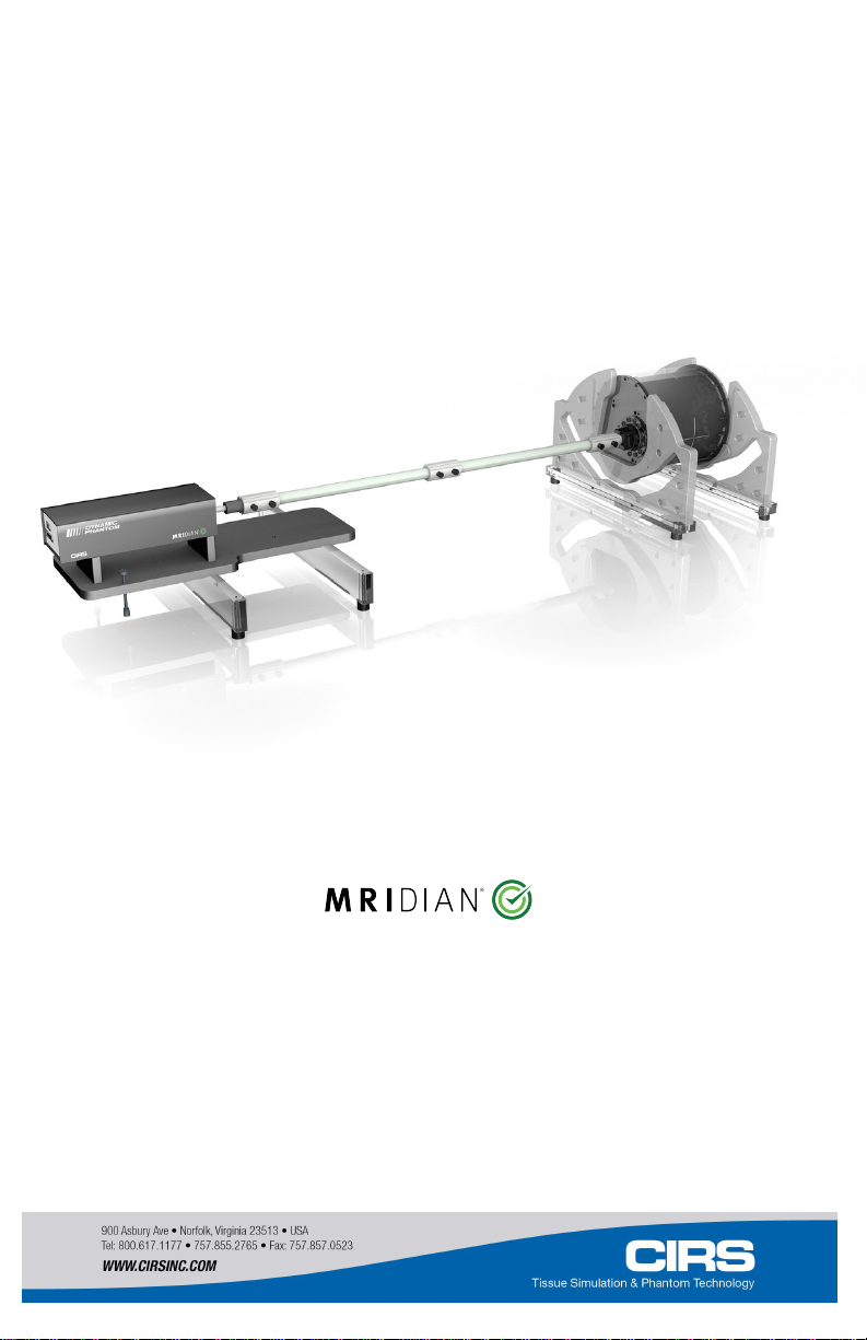
1. Remove MRI Body/Torso Coils supports and set them
aside. Pay attention to the foam trays that accommodate
these parts as they are fragile.
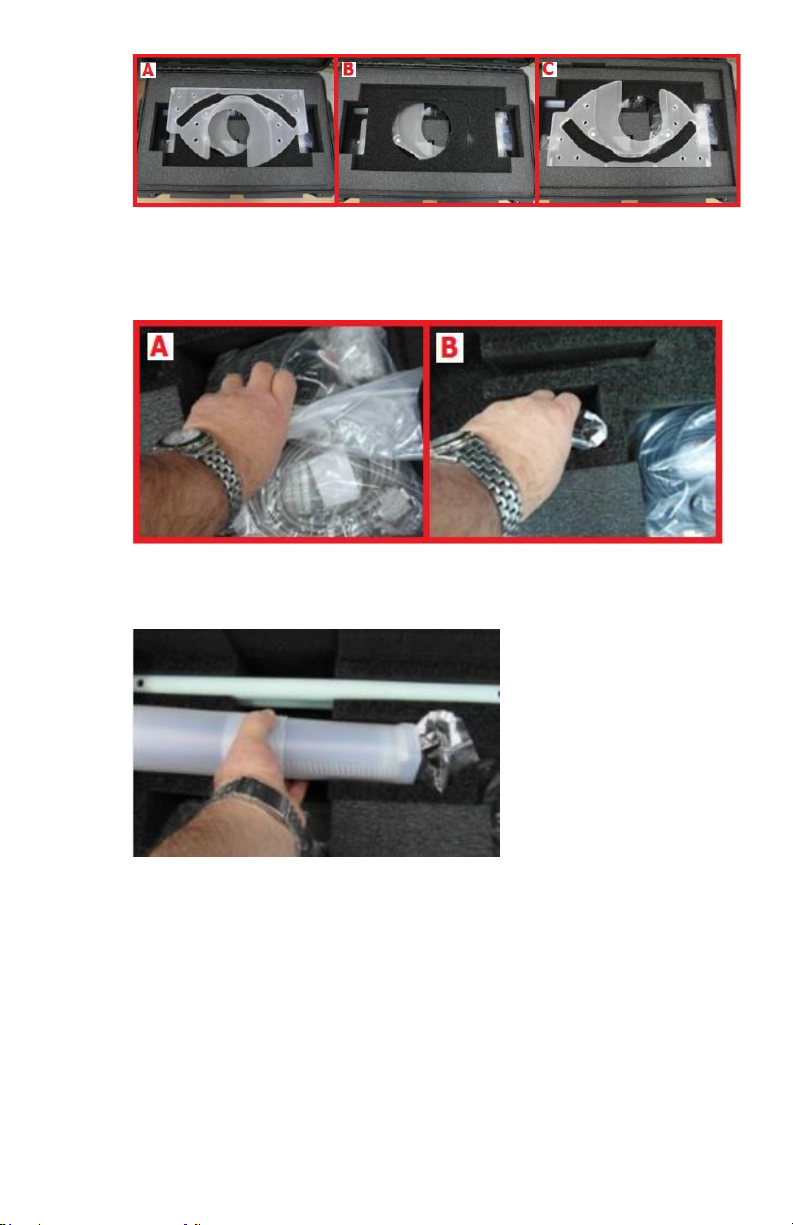
2. Remove cables and accessories bags from case and set
them aside.
3. Remove MRI Moving Rod and set it aside.
6
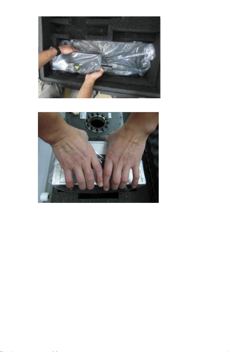
4.
Pull base and the actuator assembly from case and set it aside.
5.
Remove Motion Controller box from case and then MRI Body
Carrying Handle, which is shipped inside of one of the
removal cutout of the MRI Body.
7
6.
Carefully take the MRI Body out from the case and set it aside
in a horizontal position laying it on the straight edges of the
body’s ends.
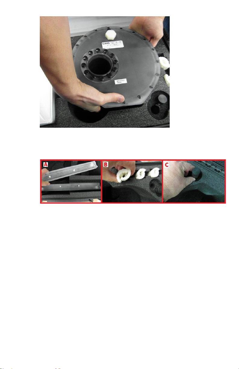
7.
Remove the remaining hardware from the case and set it
aside.

8
B. Assembly Instructions
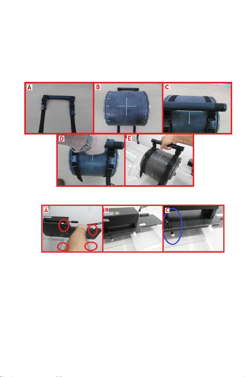
1.
Assemble the MRI Body/Viewray Torso Coils supports and
MRI Body crossbars using the alignment pins and
corresponding holes (circled in blue) and secure in place with
the black ½-13 hex nylon screws. Pair the MRI Body/Viewray
Torso Coils support with the corresponding MRI Body
crossbar, which can be identified by their labels (circled in
red).
Note: Throughout this user manual “Front” and “Back” (for
both MRI Body and actuator) are referring to such that
“Back” is the furthest from the observer when the phantom
is on the couch with the MRI Body toward the gantry and
the observer at the end of the couch. Also, to aid in correct
assembly of the phantom’s parts the
identification/matching labels are affixed only on
observer’s right side.
9
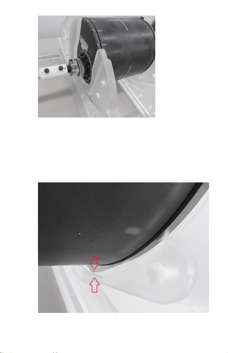
2.
After indexing the two MRI Body/Viewray Torso Coils
support - MRI Body crossbar subassemblies to the Viewray
couch ( following the naming convention explained before)
place the MRI Body between them as shown above.
Make sure the body slides inside the two supports and is
guided by the walls of the recess pockets so that it locks on
the flat faces of the MRI Body’s ends (see below).
10
To place the MRI Body on the support use the handle and the
straps like shown below (make sure the body do no slips from
the straps; carry the body as much as possible in a horizontal
position with the straps/handle position in a vertical
line/plane with the body’s top laser marks).
3. Position the Linear actuator on the other end of the couch.
The crossbars alignment pins and actuator base plate holes
facilitate a quick alignment between the Linear actuator and
MRI Body (see pictorial A). Secure the linear actuator against
tripping using the adjustable legs, which should push against
the couch (see circled in blue in pictorial C; screw the
adjustable legs through the actuator base plate and into the
toggle pads, which are found in the accessories bag).
11
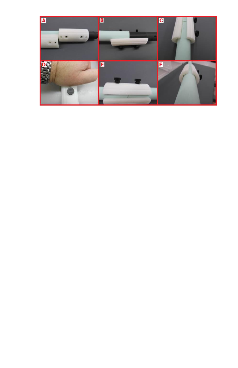
4.
Connect the shafts together and to the actuator push rod
following the sequence from the above pictorials.
The recommended procedure is:
-Identify the top connector bridge (white nylon pieces)
with un-threaded large holes (pictorial A) and align the
holes of shafts/Absylux connectors with the conical posts
of the said bridge (pictorial B).
-Pass two ¼-20 -1.5” long nylon thumb screws through the
holes of top connector bridge and shafts/Absylux
connectors then screw them in the bottom connector
bridge as shown in pictorial C.
-If it becomes hard to screw the thumb screws one can
press the whole assembly against a hard flat surface with
the bottom connector bridge down (pictorial D) until a
result like shown in pictorial E is obtained.
-Tight the thumb screws so that both the top and bottom
connector bridges touch the shafts/Absylux connectors.
Do not over tight.
12
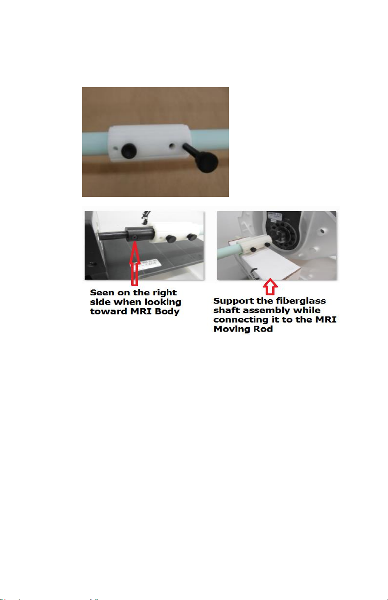
Note: If there is a need to remove the bridge connectors and
they seem to be locked on the shafts use the thumb screws to
push against (by screwing them in the outer treaded holes)
the shaft, which will un-lock them (see below).
5. For proper alignment of actuator with MRI Moving Rod
follow the assembly steps shown above.
13
C. Oscilloscope Connection
The phantom is equipped with a special feature that allows
the end user to check whether there is latency between the
position of the MRI moving target and the release of the beam
based on MRI imaging of the this target.
To accomplish this task the phantom is equipped with:
I. An assembly containing two optical switches, which is
housed inside of the main linear actuator of the phantom.
When the lead screw of the linear motor crosses the
optical switches it provides two electrical signals that can
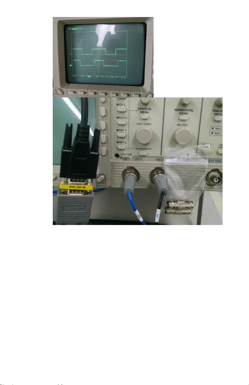
be analyzed on an oscilloscope. The signal from each
individual optical switch is a square wave as shown
below.
14
II. Cable that allows analyzing two signals at once, on
channel 1 and 2 of an oscilloscope respectively.
To do adjustments to the signal that is provided by the optical
switches and to analyze them on an oscilloscope follow the following
steps:
15
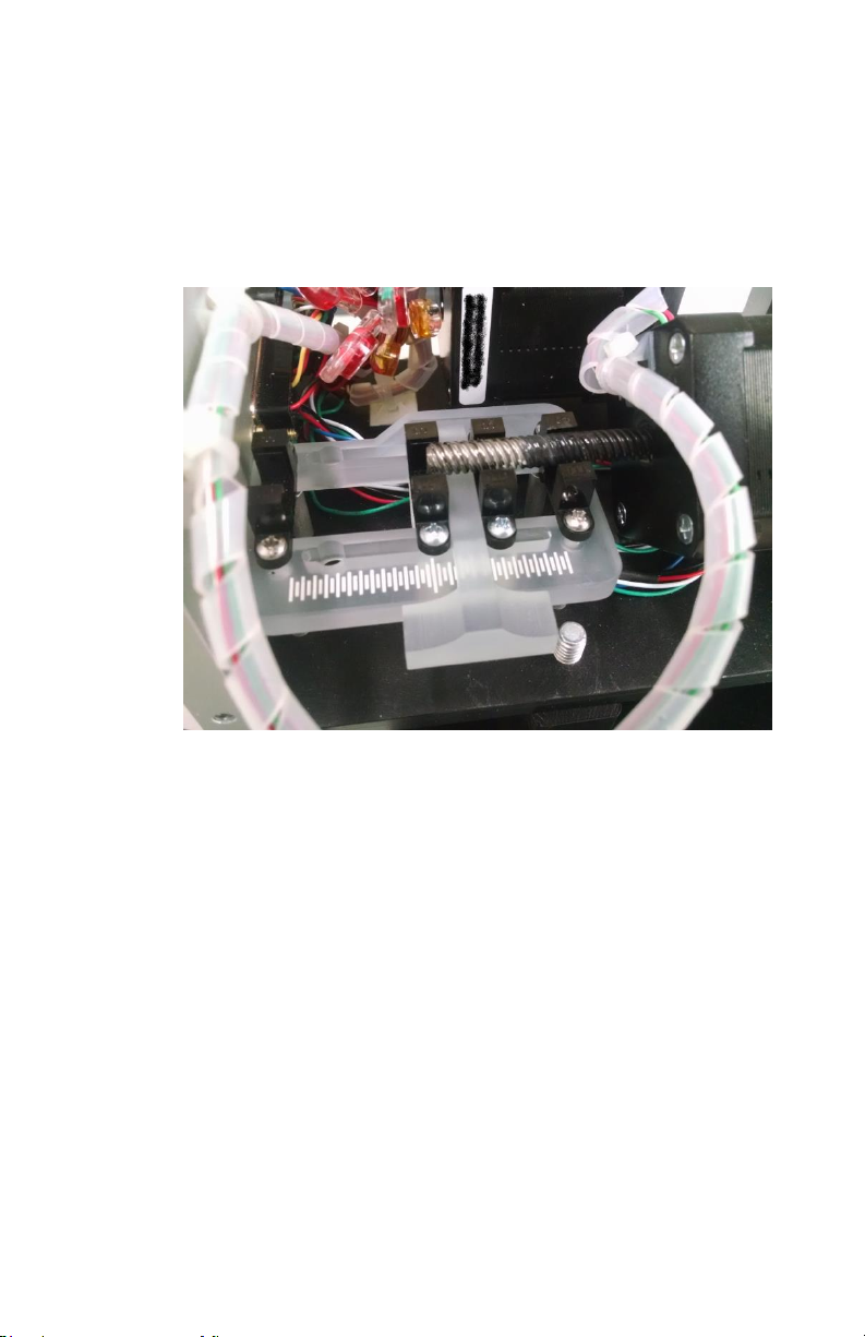
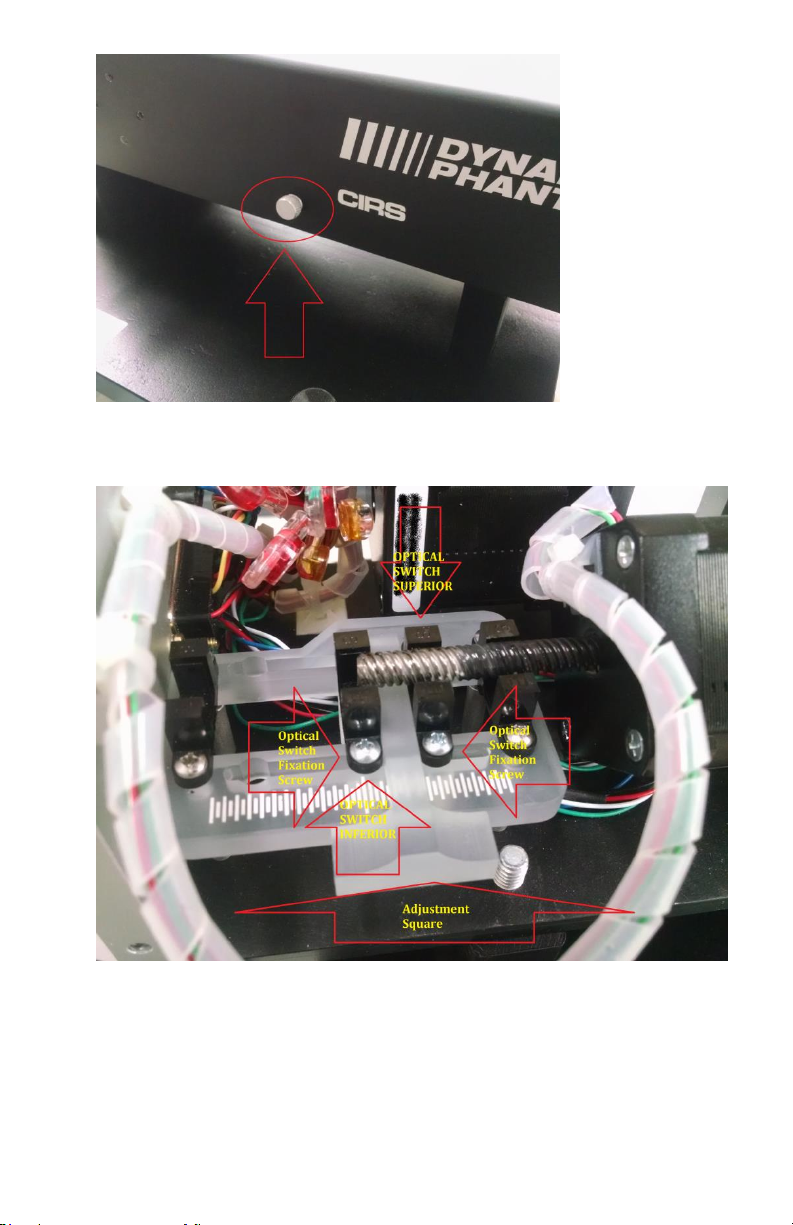
1. Open the cover of the actuator box by unscrewing the aluminum
thumb screws (see above) and remove it.
2. Unscrew the Optical switch fixation screw of the two inner
Optical Switches and adjust the distance between them according
to your research study. Use the Adjustment Square to align the
Optical Switches at 90ºwith respect the slots of the assembly
support.
16
Note: The position of the outer two Optical Switches is not
adjustable. Do not unscrew their fixation screws. These two
Optical Switches are used for safety limits of the travel of the
linear motion and for the homing sequence.
3. Close the cover of the actuator box by hand tightening the
aluminum thumb screws.
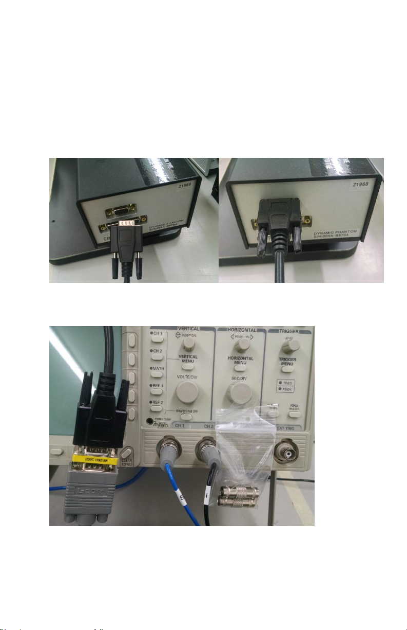
4. Connect one of the provided DB9 shielded cable to the DB9
Female connector at the back of the actuator.
5. Connect the short DB9 to Oscilloscope cable to the DB9 cable that
was connected to the actuator. A DB9 Female to DB9 Female and
extra connectors are provided for convenience.
17
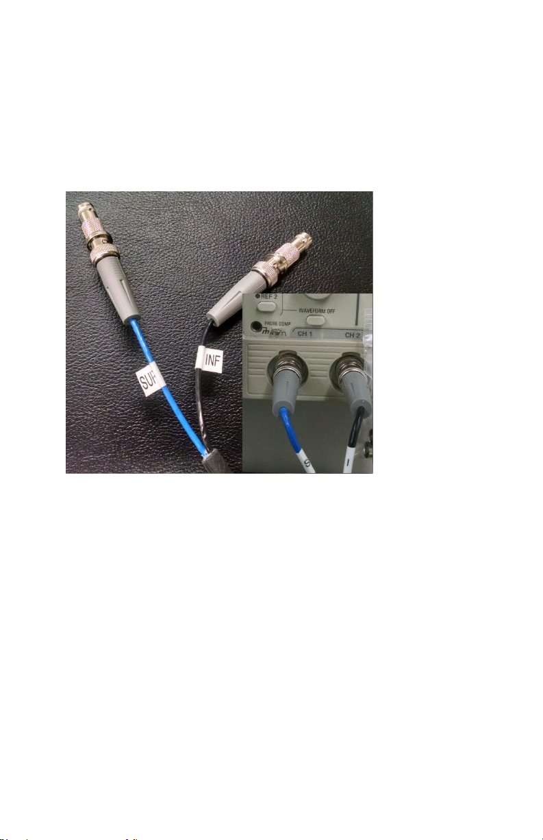
Note: The short DB9 to Oscilloscope cable has its oscilloscope
labeled as SUP for the Optical Switch that is toward the linear
motor and INF for that is toward the back of the actuator due
to the fact that the Phantom is designed for “Supine Head
First”. As shown below it is recommended that SUP signal is
analyzed on Chanel 1 and INF on Chanel 2 of the oscilloscope.
D.. Repacking Instructions
User should try to follow the unpacking steps in a reverse
order.

Included with Model 008V
18
-(1) Base Plate with Linear Actuator mounted (with 2
Adjustable Legs already mounted)
-(1) MRI Moving Rod
-(2) Motion Transmission Shaft
-(1) MRI Body/Torso Coils Front support
-(1) MRI Body/Torso Coils Back support
-_(1) Bag with mandatory fasteners: 4 x Nylon Socket Head
Cap Screw 1/2"-13 Thread, 1-1/2" Length, Black 6 x
1/4-20 1.5" long Nylon Thumb Screw, 1 x 1/4-20 1" long
Nylon Thumb Screw
-(1) CIRS Motion Control Software USB Drive
-(1) Motion Controller Power cord
-(1) Cable Kit, CAT5e - 75 feet with USB 3.0 Gigabit
Ethernet Adapter
-(1) Oscilloscope Cable [VGA to DB9/4BNC Breakout cable
Male
-(2) DB-25 male to male cable (EMI Shielded)
-(2) DB-9 male to male cable (EMI Shielded)
-(2) Gender Changer DSUB 9POS F-F
-(1) Gender Changer DSUB 25POS F-F
-(1) User’s Guide
- (1) Motion Controller Box
-(1) MRI Body
-(1) MRI Body Carrying handle (with 2 straps already
mounted)
-(1) Linear Actuator Crossbar Front
-(1) Linear Actuator Crossbar Back
-(2) MRI Body Crossbar
- (3 sets) Connection bridges for Motion transmission Shaft
(2 parts per set)
-(1) Connector Motion transmission Shaft-to-MRI Moving
Rod
- (1)Nonsparking (nonmagnetic) Hex L-Key 3/8" Hex Size,
4-1/2" Long
- 10-24x1” (5); Nylon Hex Screw 1/2-13x1.5” (2)
o

19
Care & Handling
Cleaning:
The phantom is manufactured from acrylic. It is recommended
that the phantom only be cleaned with mild soap and water.
Caution: DO NOT USE ANY ABRASIVES, ALCOHOL OR SOLVENTS
ON THE
PHANTOM. These will damage your phantom.
Carrying:
- Short Distances (between couch and plastic storage case) -
Use the provided handle and straps to lift MRI Body from Coils
Support and carry it (horizontal only - see below).
- Long Distances - Use as much as possible the plastic
storage/shipping case. Make sure the MRI Body is fully
secured inside the case by using the appropriate foam blocks
as seen below.
Included with Model 008V
-(2) 2 amp fuses
-(1) Extra fasteners pack (min quantity in brackets): Nylon
Thumb Screw ¼-20x1.5” (6); Nylon Thumb Screw
¼-20x1” (2); Nylon Pan Screw ¼-20x5/8” (2+2 with O-
rings); Nylon Pan Screw 10-24x3/4” (8); Nylon Pan Screw
10-24x1” (5); Nylon Hex Screw 1/2-13x1.5” (2)
Table of contents
Other Cirs Medical Equipment manuals


Popular Medical Equipment manuals by other brands


Otto Bock
Otto Bock Dyna Ankle 50S1 Instructions for use

Physiomed
Physiomed vocaSTIM-Master operating instructions

Bodypoint
Bodypoint BB101M-1 Installation and user instructions

Bunnell
Bunnell LifePulse 204 Quick reference guide

SeilerScope
SeilerScope 935 owner's manual

imtmedical
imtmedical bellavista Quick start manual