Cirs Dynamic Phantoms 008A User manual

IMAGE ACQUISITION • TREATMENT PLANNING • DOSE DELIVERY
USER GUIDE
Dynamic Phantoms
Model 008A, 008A-20,18023-A, 18043-A
900 Asbury Ave • Norfolk, Virginia 23513 • USA • Tel: 757-855-2765 • WWW.CIRSINC.COM

Overview . . . . . . . . . . . . . . . . . . . . . . . . . . . .3
Safety . . . . . . . . . . . . . . . . . . . . . . . . . . . . . 4
Unpacking Instructions . . . . . . . . . . . . . . . . . . . . . . 5
Model 008A, 18023-A & 18043-A Assembly Procedure . . . . . . . . . 6
Removal of Ball Cube. . . . . . . . . . . . . . . . . . . . . . . 7
Model 008A, 18023-A & 18043-A Cables and Connections . . . . . . . . 8
4D CT QA Insert Set Up . . . . . . . . . . . . . . . . . . . . . .9
Setup notes for Dynamic Phantoms with controller connecting to a PC using
an Ethernet connection . . . . . . . . . . . . . . . . . . . . . 10
CIRS Motion Control Software . . . . . . . . . . . . . . . . . . 12
Model 008A Specications . . . . . . . . . . . . . . . . . . . 13
Warranty . . . . . . . . . . . . . . . . . . . . . . . . . . . 14
Notes . . . . . . . . . . . . . . . . . . . . . . . . . . . . 15
Table of Contents

3
The CIRS Dynamic Phantoms are precision instruments for investigating and mini-
mizing the impact of tumor motion inside the lung (Model 008A Dynamic Thorax
and 008A-20). These phantoms provide known, accurate and repeatable three-
dimensional motion for guided radiation therapy.
The phantom bodies represent an average human thorax/pelvis in shape, propor-
tion and composition.
Model 008A works with a lung-equivalent rod containing a spherical target with
or without various detectors that is inserted into the lung-equivalent lobe of the
phantom. The body is connected to a motion actuator box that induces three-di-
mensional target motion through linear translation and rotation of the lung equiva-
lent rod. Motion of the rod itself is radiographically invisible due to its matching
density with the surrounding material. The target and its motion, given its density
difference, can be resolved. A programmable motion controller is used to drive
the motion actuator.
Model 008A-20 includes only the thorax body and third-axis actuator.
Model 18023-A shares some components with the CIRS Model 008A Dynamic
Thorax Phantom. As with the Model 008A, target and surrogate motion are inde-
pendently controlled with CIRS Motion Control Software. The graphical user in-
terface provides an unlimited variety of motions while the key differences between
the Model 18023-A and the CIRS Model 008A include the length of phantom
body, location of the moving rod within the lung, and the inclusion of ribs.
Model 18043-A contains a cylindrical spine insert. The spine insert is trabecular
bone-equivalent and accommodates a lm cube with cylindrical critical struc-
ture and dosimetric lm for assessment of spinal cord sparing. The insert can be
manually rotated within the phantom body.The 18043-A lung has higher density
than the 008A lung. The 18043-A lung equivalent insert also accommodates a
lm cube with a spherical soft tissue target and dosimetric lm.
Overview
Key Features
• Complex 3D tumor motion
within the lung
• Sub-millimeter accuracy and
reproducibility
• Motion software enables
different cycles, amplitudes and
wave forms
• Tissue equivalent from 50 keV
to 15 MeV
• TLD, MOSFET, micro-chamber
and film can be placed within
the tumor volume

4
GENERAL SAFETY NOTICE
Warnings and Cautions are identied throughout this user guide to alert users of dangerous conditions that are created when instructions are
not followed. Operation and maintenance personnel must observe all safety regulations. For the purposes of this manual, cautions are identied
as situations that can cause damage to the phantom and internal electronics. Warnings are dened as conditions that can cause injury to the
operator.
WARNING:
HIGH VOLTAGES CAPABLE OF CAUSING DEATH ARE USED IN THIS EQUIPMENT. USE EXTREME CAUTION
WHEN OPERATING AND SERVICING THE CONTROLLER. DEENERGIZING THE CONTROLLER BY USING THE
POWER SWITCH DOES NOT REMOVE THE 110-250 VAC POWER EXCITATION FROM THE CONTROLLER.
THESE VOLTAGES REMAIN PRESENT IN THE CONTROLLER POWER SWITCH AND POWER CONNECTOR UN-
LESS IT IS DISCONNECTED.
WARNING:
TO REDUCE THE RISK OF FIRE, ELECTRIC SHOCK, OR INJURY WHEN USING THE MOTION CONTROLLER, FOL-
LOW THESE BASIC PRECAUTIONS:
• There are no user-serviceable parts inside. Refer servicing to qualied service personnel.
• Use only a grounded 3 prong electrical outlet when connecting this product to a power source. If you do not know
whether the outlet is grounded, check with a qualied electrician.
• Do not remove ground prong.
• Do not install or use this product near water, or when you are wet.
• Operate the product securely on a stable surface.
• Set up the product in a protected location where no one can step on or trip over the power cord and the power cord can
not be damaged.
• It is recommended that the customer install an AC surge arrestor in the AC outlet to which the Controller is connected.
This is to avoid damaging the equipment by local lightning strikes and other electrical surges.
• To prevent overheating, do not block the fan on the rear panel or the ventilation holes located on the rear panel
and bottom of the Controller.
CLEANING
You can clean the phantom with a soft cloth dampened with water and mild detergent. Do not use disinfectants or solvent-based cleaners or
sprays.
Safety
SAFETY PRECAUTIONS
Below is a list of specic safety precautions detailed in this user guide. Please review these precautions carefully and use care while handling the
phantom.
CAUTION:
PHANTOM ASSEMBLY REQUIRES TWO PEOPLE. ONE PERSON FOR STABILIZING AND A SECOND FOR AS-
SEMBLING THE PHANTOM. FAILURE TO STABILIZE THE BASE PLATE CAN ALSO RESULT IN DAMAGE TO THE
PHANTOM.

5
1. Before you open the case check the
three Drop ‘N’ Tell indicators on the
right side of the case.
Unpacking Instructions
Model 008A, 18023-A and 18043-A
4. Remove motion controller from case
and set aside.
3. Pull phantom body from case.
6. Remove the actuator base plate
assembly from case. 7. Inspect the list of parts before assembly.
Refer to specications on page 13. Verify
all parts received. (Parts and packaging
may vary.)
5. Remove cables.
(Optional computer is available).
2. Remove wall partition from the case and
set aside.
Drop ‘N’ Tell shipping damage indicator
shows when a case has been dropped
in transit and contains potential dam-
aged goods. The sensor displays a red
arrow when applied before shipping. If
the container receives a shock exceeding
25 G force, the sensor display arrows will
change to blue. If the sensor has been
activated and is blue, a claim may need
to be led with the carrier. If activated,
take extra care in inspecting the compo-
nents as they are unpacked, assembled
and tested.
Note: If there is any damage to the
packaging case, containers, foam,
and components, or operation, Im-
mediately contact the carrier and the
phantom supplier, and keep all pack-
aging for carrier inspection.
6
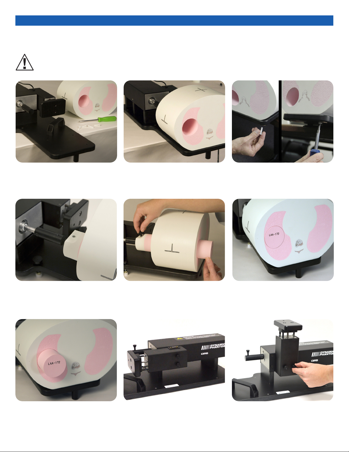
Model 008A, 18023-A & 18043-A Assembly Procedure
1. Place base plate with actuator assembly
on table. Carefully move base plate to
overhang table. This allows access to
holes for attaching phantom body.
2. Position phantom body on base plate as
shown. The rod hole must be on same
side and aligned with the rod holder.
3. Place one screw through bottom of base
plate and screw into phantom. Continue
until all screws are in place. Snug but do
not tighten screws to allow minor align-
ment adjustments in steps 6 and 7.
4. Insert lung rod thru hole in phantom
body. Ensure that screw hole on lung rod
is aligned with screw hole on actuator
rod.
5. Use thumb screw to secure lung rod to
actuator rod. 6. Push lung rod towards the motor box.
Visually check gap around the rod. It
should appear consistent. If not, adjust
body left and right until gap is consistent
around rod.
7. Repeat step 6 with rod extended out.
Check gap on the motor box side of
body as well. Adjust phantom body to
achieve best t. Finish tightening the
screws on underside of phantom.
8. 3rd axis actuator is shipped in the
horizontal position. 9. Move 3rd axis gating device to vertical
position by loosening screws and
repositioning as shown.
CAUTION:
PHANTOM ASSEMBLY REQUIRES 2 PEOPLE. ONE PERSON FOR STABILIZING AND A SECOND FOR ASSEMBLING THE PHANTOM.
FAILURE TO STABILIZE THE BASE PLATE CAN RESULT IN DAMAGE TO THE PHANTOM.
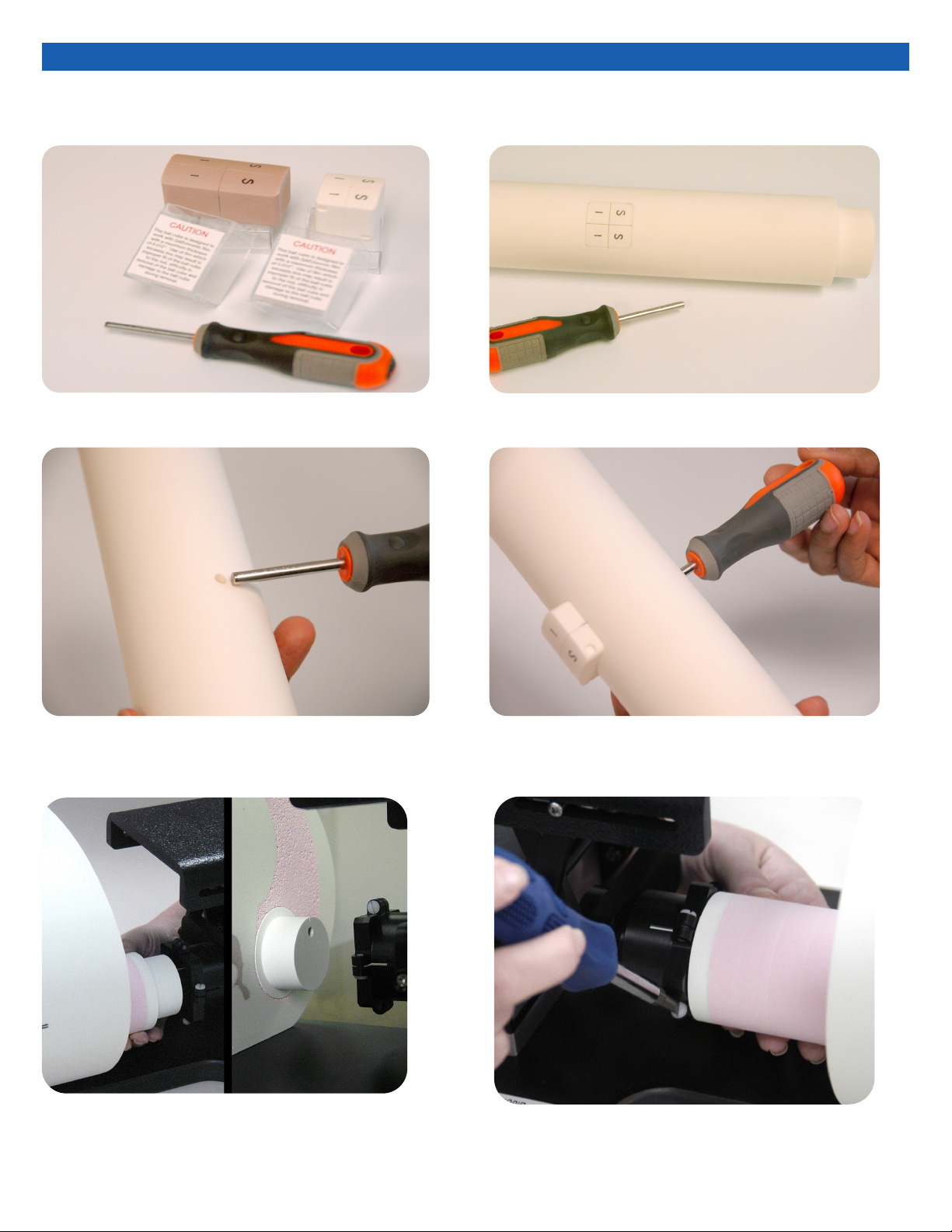
Removal of Ball Cube Insert (Optional)
1. CIRS has provided a Ball Cube Removal Tool. Please note
precautions on Ball Cube insert packaging.
2. Insert Ball Cube Removal Tool into back of Target Moving Rod
at insertion point as shown above. 3. Gently push forward until Ball Cube is removed. Do not use
other tools for this purpose as they may damage the surface of
the Ball Cube which is fragile.
5. Use a screw driver to tighten the 4 nylon screws on the
cup.
4. The Model 18023-A and 18043-A rods connect to the motion
actuator with cup holders. Insert the lung rod thru the hole of
the phantom body. If the body is properly aligned the rod will
slip into the cup. Ensure that the pin hole on the rod is aligned
with the pin inside the cup.
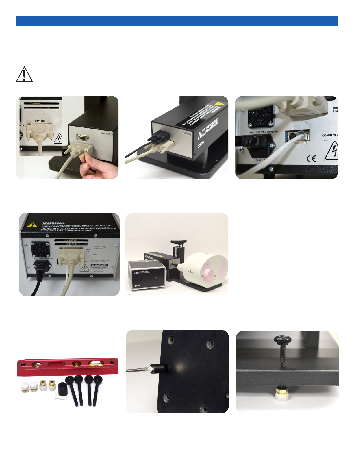
8
3. Attach ethernet cable to back of
controller.
4. Plug power cord into the back of
controller. Plug other end of
power cord into the wall outlet.
1. Plug the Cable DB25 m/m to back of
controller and to back of actuator.
5. The controller and actuator powered
and ready for use.
2. Plug the Cable DB9 m/m which
leads from gating device to back
of actuator.
Model 008A, 18023-A & 18043-A Cables and
Connections
A. Adjustable legs kit (See B and C for
mounting) B. Prior to attaching phantom body, care-
fully lay base plate with actuator in its
side. Attach solid black post to un-
derside of base plate as shown.
C. Secure remaining 4 adjustable feet to
base plate as shown.
WARNING:
FOLLOW THE CABLE CONNECTION STEPS AS THEY ARE PRESENTED IN THIS USER GUIDE.
CONNECTING THE CABLES WITH THE CONTROLLER “POWER ON” CAN SERIOUSLY DAMAGE THE PHANTOM’S ELECTRONICS.

9
1. Insert the 4D CT QA moving rod into the
rod holder and secure using nylon
screws.
Insert the 4D CT QA static cylinder into
the phantom’s horizontal hole and se-
cure using the rubber gasket.
Static position on a preliminary CT scan
4D CT QA Insert (Model 008A option)
3. Run phantom Homing (automatic when
powered on). Perform a preliminary CT
scan in “home” position without motion
in order to verify alignment of moving
ducial to static grid ducials. The 4D CT
QA Moving Rod position may need to be
adjusted to ensure proper alignment.
Adjustments can be made by changing
“Start Position” in the Advanced Motion
Parameters window.
2. For IS and AP tests, position static cylin-
der with square end mark at 9 o’clock
using level or machine square.
For IS and LR tests, position static cylin-
der with square end mark at 12 o’clock
using level or machine square.
4. Static grid ducials have an increment of
5 mm and provides maximum displace-
ment of +/- 15 mm in IS direction and
+/- 10 mm in LR or AP directions. Set
motion amplitudes within these limits
in increments of 5 mm:
• For IS: IS per your choice, LR and
AP= 0, start angle 0 or 90 degrees
• For LR: IS= 0, LR per your choice,
AP= 0, start angle 0 degree
• For AP: IS= 0, LR= 0, AP per your
choice, start angle 90 degree
5. Run phantom and perform 4D CT imag-
ing. Obtain test results from the 4D CT
sorted images. Report results as the
difference (in mm) between the moving
and static ducials when positioned at
0% and 50% phases.
6. If the moving ducial starting position is
aligned with the static ducial during pre-
liminary static CT scan, then the results
of 4D CT binning can be checked for the
maximum and minimum amplitudes,
respectively 0% and 50% phases. Since
both static and moving ducials measure
1 mm in diameter, misalignments as
small as 0.5 mm can be easily visualized.
The software measurement tool allows
precise evaluation of these misalign-
ments. If a discrepancy is discovered,
check equipment and/or adjust treat-
ment safety margins.
7. Due to its regular size and cylindrical
shape, the moving rod can be used for
motion artifact evaluation. The plunger
that carries the moving ducial is cylin-
drical in shape (45.7 mm diameter x
20.0 mm long) and can be used to
investigate artifacts, volumes, and
shapes during different breathing mo-
tions, including patient-specic motion
proles.
Left: Linear Phase 0% at 10 mm amplitude
Right: Rotation Phase 50% lateral 5 mm amplitude
Left: IS and AP Tests, Right: IS and LR Tests
CIRS Motion Software Advanced Motion Param-
Moving Rod and plunger with ducial

10
The following are the recommended steps to install the “USB to Network Adapter” that was shipped with this phantom. The new Net-
work Connection must be setup as a Static IP address in order for the PC to communicate with the motion controller of the phantom.
Setup notes for Dynamic Phantoms with controller
connecting to a PC using an Ethernet connection:
Note: The provided “USB to Network Adapter” can act as Plug and
Play device on some PC but CIRS recommends doing the installation
of the driver as outlined above.
1. To install the necessary driver, unzip the “USB-to-Network
Adapter” folder found on the provided USB drive or download
the zipped folder from the CIRS website. Archive to a known
location and select autorun.
3. Follow the on screen steps and acknowledge all the mes-
sages related to driver’s installation. Once the driver installa-
tion is nished, plug the “USB-to-Network Adapter” into
your PC’s USB port and acknowledge the Windows installa-
tion message. Exit the “USB-to-Network Adapter Software”
menu by clicking Exit.
4. From the Control Panel, open the Network and Sharing Cen-
ter and then select “Change adapter settings”.
2. Let your Windows OS select the most appropriate driver by
selecting “Install Driver”.
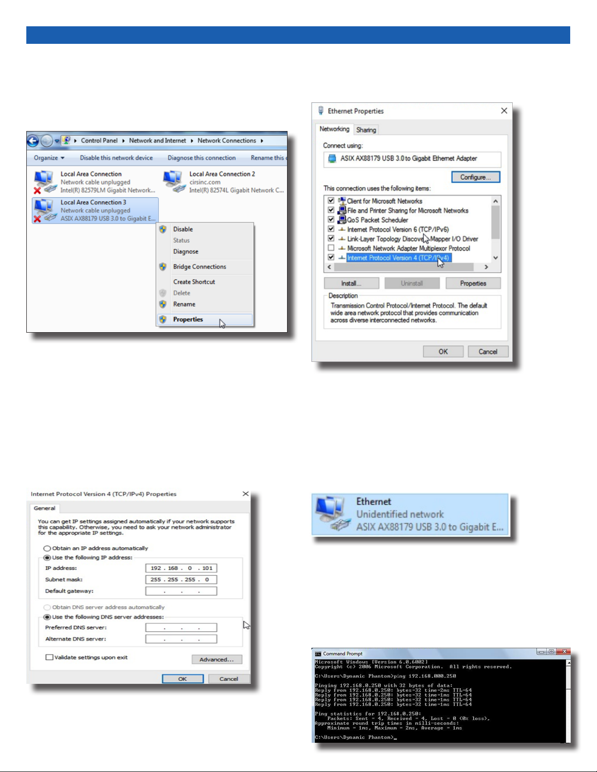
11
6. Select Internet Protocol Version 4 (TCP/IPv4) and click on prop-
erties
5. Providing that the installation of the “USB-to-Network Card”
was successful, the newly installed Network Adapter should
show as “ASIX AX88179 USB 3.0 to Gigabit Ethernet Adapter”.
Select it’s Properties using the right mouse click menu as
shown below.
7. In the internet Protocol Version 4 (TCP/IPv4) properties window,
change from default “Obtain an IP address automatically” to
“Use the following IP address:” Enter “192.168.0.101” as the
IP address and “255.255.255.000” as the Subnet mask.
Note: If an IP address conict occurs because IP address
192.168.0.101 is already assigned to another Net
work Adapter, the user can try any other IP address between
192.168.0.102 and 192.168.0.249.
8. Once the IP address is entered, click OK. Connect the PC to
the Controller using the provided Ethernet cable by inserting
one end of the cable in the controller’s Ethernet port and the
other one in the “USB-to-Network Adapter”. Power on the
controller. To check that the PC to controller connection was
successful, ensure the icon of the “ASIX AX88179 USB 3.0 to
Gigabit Ethernet Adapter” in the Control Panel matches the
image below. Network Connection can be renamed using the
right mouse click menu.
9. A more in depth check of the PC-to-controller communication
connection can be done by running a “ping command” in Com-
mand Prompt as seen in the image below. To ping the controller,
type “ping 192.168.0.250” and press enter. Ping certies
IP-level connectivity to another TCP/IP device. If you receive
Ping statistics for IP address 192.168.0.250 (controller IP ad-
dress) the communication connection between the PC and
controller was successful.
12
CIRS MOTION CONTROL SOFTWARE SYSTEM
REQUIREMENTS
Windows XP® / Vista / Windows 7/ Windows 8/ Windows 10
(32 and 64 Bit)
Pentium 3® or equivalent
512 MB RAM, 2 MB of available disk space
INTRODUCTION
CIRS Motion Control is an application which allows you to control
the movement of the CIRS Model 008A Dynamic Thorax Phantom
and model 008PL Dynamic Platform. With CIRS Motion Control, you
can quickly set up a movement based on a library of pre-dened
motions, including Sin, Cos4, Cos6, Sawtooth, Sharkn, Hyster-
esis ( Model 008A only) and Continuous Drift, Transient Excursion,
Persistent Excursion, High-Frequency Excursion, or you can import
custom motion data from any tab-delimited or comma- separated
text le. CIRS Motion Control also allows you to save any motion
to easily access the same parameters for repeated calibration and
testing.
INSTALLATION
The CIRS Motion Control application requires the Trio PC Motion
library, which allows the computer to recognize the Trio controller
board in the Dynamic Phantom or Platform. To install the Trio PC
Motion library, double-click Trio_PC_Motion_ActiveX_2_6_15_Setup
and follow the steps in the InstallShield Wizard.
To install CIRS Motion Control, double-click MotionControl-
Setup or Setup and follow the steps in the Setup Wizard. The
Microsoft.NET Framework Version 3.5 is required for the ap-
plication to run.
GENERAL USE
The CIRS Motion Control Software is preinstalled on the optional
computer. Help can be launched from Help Menu. A copy of the
software is included on a USB drive.
CIRS does not support 3rd party equipment. Please refer to the
included documents for warranty and service information for the
ACER brand computer (computer optional).
The software automatically creates a log le where data about wave-
form parameters are saved. The log le is usually located under the
current user in the Application Data folder. A Windows OS search
function can be used to nd the log le. Searching hidden les and
folders should be enabled.
The log le provides a record of the motion history of the device and
can be used as objective evidence that proper QA was performed.
CIRS Motion Control Software
SOFTWARE USER MANUAL & SOFTWARE UPGRADES
CIRS Motion Control software has an online user manual. After
software installation, a copy may be viewed and downloaded using
either the “Check for Updates” button from Help Menu and selecting
“Motion Control User Manual.pdf” or by pointing a web browser to
the CIRS Software Updates webpage: http://www.cirsinc.com/Mo-
tionControlUpdates/Motion_Control_User_Manual.pdf
If the end-user is ofine during use of the phantom, it is recom-
mended that a copy of the CIRS Motion Control User Manual is
downloaded and saved. Once a copy of the manual is saved in a
known location, the PDF document can be opened and viewed in a
window separate from the CIRS Motion Control software window to
aid in phantom set up and use.
The user manual is regularly updated to incorporate new information
based on the addition and/or modication of features as well as end-
user feedback.
CIRS recommends that the end-user routinely check the CIRS Soft-
ware Update webpage using the “Check for Updates” button from
Help Menu. This page indicates the current software version. The
latest free software upgrade is posted as soon as it becomes avail-
able. Instructions for updating the software are also posted. Please
note, when updating WIndows operating system, the controller may
need to be updated as well, requiring return to CIRS. See https://
www.cirsinc.com/software/motion-control/ for more information.

13
OVERALL DIMENSIONS: 67 cm x 32 cm x 28 cm (26’ x 13’ 11’)
OVERALL WEIGHT: 17.2 kg (37.9 lb)
POWER: 110-250 VAC, 50/60 Hz
AMPLITUDE, IS: ± 25 mm
AMPLITUDE, AP/LR: ± 5 mm
AMPLITUDE, SURROGATE: ± 25 mm
MAX. SURROGATE PLATFORM LOAD 5.4 kg (12 lb)
MOTION ACCURACY: ± 0.1 mm
CYCLE TIME: 1 - ∞ (adjusted based on amplitude)
Model 008A Specications
Part No. Qty Component Description
008A 1 Dynamic Thorax Phantom Body with 3D spine
(Dosimeter & QA rods not included )
1 Dynamic Motion Controller with rmware installed
(110 - 220V, 50 - 60Hz)
1 Actuator base plate assembly
1 3rd axis gating device (mounted to actuator base
plate assembly)
1 CIRS Motion Control Software USB
1 Cable kit: USB 3.0 Gigabit Ethernet Adapter, Net-
work cable CAT5e, 75’, DB 25 male to male cable,
DB 9 male to male cable, Power cord
1 Accessories Kit: 4 in 1 screwdriver, push rod,
fasteners pack, 2 spare fuses
1 Adjustable legs kit: level, 4 adjustable legs with feet,
post with screw
1 User’s guide (PDF user guide and catalog included
on provided USB)
1 Carry Case
OPTIONAL ACCESSORIESINCLUDED WITH MODEL 008A
Note: Customers must complete their order with the purchase of at least one
(1) interchangeable insert option. *Refer to separate CIRS cavity and plug
code list for available chamber cavities.
Part No. Description
008A-05 MOSFET congured lung equivalent rod with set of 3 target
inserts
008A-
06-CV*
MICRO CHAMBER congured lung equivalent rod with set of
3 target inserts
008A-08 Radiochromic lm congured lung equivalent rod
008A-11 GEL DOSIMETRY congured lung equivalent rod with CIRS
Model B-9, Dose Gel Container
008A-12 4D CT QA Device
008A-14 Lung equivalent Imaging Rod with set of 3 target inserts
008A-15 PET/CT congured lung equivalent rod with set of 3 target
inserts
008A-17 Adjustable legs kit
008A-19 Ball Cube congured lung equivalent rod for lm dosimetry
008A-22 SBRT Rod with set of 3 target inserts
008A-24 OSL Dosimetry Rod with 3 cm Target insert
008A-153 Replacement Push Rod
008A-125 Chest plate with reective 11.5 mm tracker balls
008-18 Model 008 upgrade to 008A
008A-253 Cable CAT5E 150 Feet for Dynamic Phantom (008A, 008M,)

14
All standard CIRS products and accessories are warranted by CIRS
against defects in material and workmanship for a period as speci-
ed below. During the warranty period, the manufacturer will repair
or, at its option, replace, at no charge, a product containing such
defect provided it is returned, transportation prepaid, to the manu-
facturer. Products repaired in warranty will be returned transportation
prepaid.
There are no warranties, expressed or implied, including without
limitation any implied warranty of merchantability or tness, which
extend beyond the description on the face hereof. This expressed
warranty excludes coverage of, and does not provide relief for,
incidental or consequential damages of any kind or nature, includ-
ing but not limited to loss of use, loss of sales or inconvenience. The
exclusive remedy of the purchaser is limited to repair, recalibration,
or replacement of the product at manufacturer’s option.
This warranty does not apply if the product, as determined by the
manufacturer, is defective because of normal wear, accident, mis-
use, or modication.
NON-WARRANTY SERVICE
If repairs or replacement not covered by this warranty are required, a
repair estimate will be submitted for approval before proceeding with
said repair or replacement.
PRODUCT WARRANTY PERIOD
Model 008A- Dynamic Thorax
Phantom and accessories 24 Months
Warranty
RETURNS
If you are not satisfied with your purchase for any reason, please
contact your local distributor prior to returning the product. Visit
https://www.cirsinc.com/distributors/ to find your local distributor. If
you purchased your product direct through CIRS, call Customer
Service at 800-617-1177, email [email protected], or fax an RMA
request form to 757-857-0523. CIRS staff will attempt to remedy
the issue via phone or email as soon as possible. If unable to correct
the problem, a return material authorization (RMA) number will be
issued. Non-standard or “customized” products may not be
returned for refund or exchange unless such product is deemed by
CIRS not to comply with documented order specifications. You
must return the product to CIRS within 30 calendar days of the issu-
ance of the RMA. All returns should be packed in the original cases
and or packaging and must include any accessories, manuals and
documentation that shipped with the product. The RMA number
must be clearly indicated on the outside of each returned package.
CIRS recommends that you use a carrier that offers shipment
tracking for all returns and insure the full value of your package so
that you are completely protected if the shipment is lost or damaged
in transit. If you choose not to use a carrier that offers tracking or
insure the product, you will be responsible for any loss or damage to
the product during shipping. CIRS will not be responsible for lost or
damaged return shipments. Return freight and insurance is to be
pre-paid.
With RMA number, items may be returned to:
CIRS
Receiving
900 Asbury Ave,
Norfolk, Virginia, 23513 USA

15
NOTES:

©2013 Computerized Imaging Reference Systems, Inc. All rights
reserved.
All brand names, product names or trademarks belong to
their respective holders.
Specifications subject to change without notice.
Publication: DYNAMIC UG 110320
Computerized Imaging Reference Systems, Inc. has
been certied by UL DQS Inc. to (ISO) 13485:2016.
Certicate Registration No.10000905-MP2016.
COMPUTERIZED IMAGING
REFERENCE SYSTEMS, INC.
900 Asbury Ave
Norfolk, Virginia 23513 USA
Toll Free: 800.617.1177
Tel: 757.855.2765
Fax: 757.857.0523
Email [email protected]
www.cirsinc.com
Technical Assistance
1.800.617.1177
This manual suits for next models
7
Table of contents
Other Cirs Medical Equipment manuals

Cirs
Cirs MRIdian Phantom User manual

Cirs
Cirs ATS 523A User manual

Cirs
Cirs 015DM User manual

Cirs
Cirs Brachytherapy QA Phantom User manual

Cirs
Cirs SHANE 13650001 User manual

Cirs
Cirs ATS539 User manual

Cirs
Cirs 604-GS User manual

Cirs
Cirs 715 User manual

Cirs
Cirs 053S User manual

Cirs
Cirs 008PL User manual


Popular Medical Equipment manuals by other brands


Bolder Surgical
Bolder Surgical CoolSeal GENERATOR user guide

Drive DeVilbiss Healthcare
Drive DeVilbiss Healthcare Samsoft 175 user manual

Adept Medical
Adept Medical AM1000 instructions

ConMed
ConMed 7-796-18BX Instructions for use

OEC
OEC MINI6600 Periodic Maintenance Procedure

Dräger
Dräger DrugTest 5000 STK Instructions for use