Cirs 008C User manual

USER GUIDE
Dynamic Cardiac Phantom
Model 008C
900 Asbury Ave • Norfolk, Virginia 23513 • USA • Tel: 757-855-2765 • WWW.CIRSINC.COM


Overview . . . . . . . . . . . . . . . . . . . . . . . . . . . .4
Safety . . . . . . . . . . . . . . . . . . . . . . . . . . . . . 5
Unpacking Instructions . . . . . . . . . . . . . . . . . . . . . . 6
Assembly Procedure . . . . . . . . . . . . . . . . . . . . . . . 7
Cables and Connections. . . . . . . . . . . . . . . . . . . . . . 8
ECG Output . . . . . . . . . . . . . . . . . . . . . . . . . . . 9
Model 008C-01 Target Detection Rod Assembly Procedure . . . . . . . 9
Setup notes for Dynamic Phantoms with controller connecting to a PC using
an Ethernet connection . . . . . . . . . . . . . . . . . . . . . 10
CIRS Motion Control Software . . . . . . . . . . . . . . . . . . 12
Model 008C Specifications & Ordering Information . . . . . . . . . 14
Warranty . . . . . . . . . . . . . . . . . . . . . . . . . . . 15
Table of Contents

4
The CIRS Dynamic Cardiac Phantom is a precision instrument that simulates the realistic
motion of an average human heart. It provides known, accurate and repeatable 3D motion
of a solid heart model inside the tissue-equivalent thorax phantom. This phantom is de-
signed as a comprehensive image analysis tool for calcification detection, iodine contrast
resolution and ECG signal gating.
The cardiac phantom is constructed from the tissue equivalent thorax body, moving rod
with the solid tissue equivalent heart inside, motion actuator, motion controller and CIRS
Motion Control software.
Overview
Model 008C Advanced
Features
• Anthropomorphic heart inside
a thorax body
• Tissue equivalent materials
• Iodine contrast and
calcification detection
capabilities
• Contrast target
interchangeability
• Complex heart motion
combined with respiratory
motion
• Sub-millimeter accuracy and
reproducibility
• Motion software enables
different cycles, amplitudes,
and wave forms
• Correlated ECG signal with
readable output

5
GENERAL SAFETY NOTICE
Warnings and Cautions are identified throughout this user guide to alert users of dangerous conditions that are created when instructions are
not followed. Operation and maintenance personnel must observe all safety regulations. For the purposes of this manual, cautions are identified
as situations that can cause damage to the phantom and internal electronics. Warnings are defined as conditions that can cause injury to the
operator.
WARNING:
HIGH VOLTAGES CAPABLE OF CAUSING DEATH ARE USED IN THIS EQUIPMENT. USE EXTREME CAUTION
WHEN OPERATING AND SERVICING THE CONTROLLER. DEENERGIZING THE CONTROLLER BY USING THE
POWER SWITCH DOES NOT REMOVE THE 110-250 VAC POWER EXCITATION FROM THE CONTROLLER.
THESE VOLTAGES REMAIN PRESENT IN THE CONTROLLER POWER SWITCH AND POWER CONNECTOR UN-
LESS IT IS DISCONNECTED.
WARNING:
TO REDUCE THE RISK OF FIRE, ELECTRIC SHOCK, OR INJURY WHEN USING THE MOTION CONTROLLER, FOL-
LOW THESE BASIC PRECAUTIONS:
• There are no user-serviceable parts inside. Refer servicing to qualified service personnel.
• Use only a grounded 3 prong electrical outlet when connecting this product to a power source. If you do not know
whether the outlet is grounded, check with a qualified electrician.
• Do not remove ground prong.
• Do not install or use this product near water, or when you are wet.
• Operate the product securely on a stable surface.
• Set up the product in a protected location where no one can step on or trip over the power cord and the power cord can
not be damaged.
• It is recommended that the customer install an AC surge arrestor in the AC outlet to which the Controller is connected.
This is to avoid damaging the equipment by local lightning strikes and other electrical surges.
• To prevent overheating, do not block the fan on the rear panel or the ventilation holes located on the rear panel
and bottom of the Controller.
CLEANING
You can clean the phantom with a soft cloth dampened with water and mild detergent. Do not use disinfectants or solvent-based cleaners or
sprays. Lithium grease is used to coat the cardiac rod. You can clean the rod with a soft cloth with dampened water and mild detergent and
then reapply the lithium grease with the supplied container of extra grease.
Safety
SAFETY PRECAUTIONS
Below is a list of specific safety precautions detailed in this user guide. Please review these precautions carefully and use care while handling the
phantom.
CAUTION:
PHANTOM ASSEMBLY REQUIRES TWO PEOPLE. ONE PERSON FOR STABILIZING AND A SECOND FOR AS-
SEMBLING THE PHANTOM. FAILURE TO STABILIZE THE BASE PLATE CAN ALSO RESULT IN DAMAGE TO THE
PHANTOM.

6
1. Before you open the case check the
three Drop ‘N’ Tell indicators on the
right side of the case.
Unpacking Instructions for All Dynamic Phantoms
4. Remove controller unit from case
and set aside.
6. Remove any rods from case.
3. Pull phantom body from case.
7. Pull base and the actuator assembly
from case. 8. Inspect the list of parts before assembly.
Refer to pack list in case. Verify all parts
received.
5. Remove computer and cables.
(Optional computer is available).
2. Remove wall partition from the case and
set aside.
Drop ‘N’ Tell shipping damage indicator
shows when a case has been dropped
in transit and contains potential dam-
aged goods. The sensor displays a red
arrow when applied before shipping. If
the container receives a shock exceeding
25 G force, the sensor display arrows will
change to blue. If the sensor has been
activated and is blue, a claim may need
to be filed with the carrier. If activated,
take extra care in inspecting the compo-
nents as they are unpacked, assembled
and tested.
Note: If there is any damage to the
packaging case, containers, foam,
and components, or operation, Im-
mediately contact the carrier and the
phantom supplier, and keep all pack-
aging for carrier inspection.
7
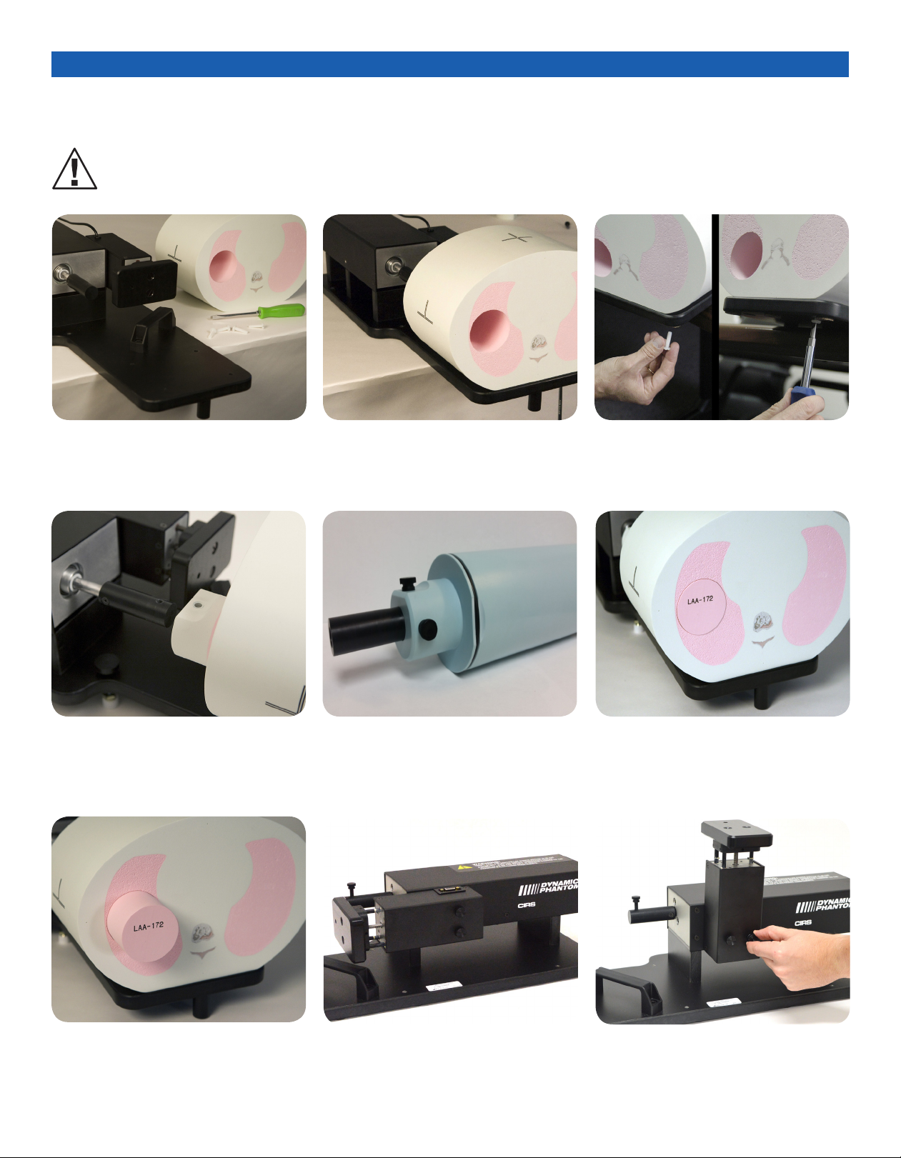
Assembly Procedure for All Dynamic Phantoms
1. Place base plate with actuator assembly
on table. Carefully move base plate to
overhang table. This allows access to
holes for attaching phantom body.
2. Position phantom body on base plate as
shown. To ensure proper alignment for
model 008C, the phantom face with the
CIRS label should be facing away from
the actuator.
3. Place one screw through bottom of base
plate and screw into phantom. Continue
until all screws are in place. Snug but do
not tighten screws to allow minor align-
ment adjustments in steps 6 and 7.
4. Insert rod thru hole in phantom body.
Ensure that screw hole on rod is aligned
with screw hole on actuator
rod.
5. Use thumb screw to secure rod to
actuator rod. For Model 008C, use two
thumb screws to secure rod to the
actuator rod. Use the ¾” screw in the flat
top hole, and the 1” screw in the perpen-
dicular hole
6. Push rod towards the motor box.
Visually check gap around the rod. It
should appear consistent. If not, adjust
body left and right until gap is consistent
around rod.
7. Repeat step 6 with rod extended out.
Check gap on the motor box side of
body as well. Adjust phantom body to
achieve best fit. Finish tightening the
screws on underside of phantom.
8. 3rd axis actuator is shipped in the hori-
zontal position. 9. Move 3rd axis device to vertical position
by loosening screws and repositioning
as shown.
CAUTION:
PHANTOM ASSEMBLY REQUIRES 2 PEOPLE. ONE PERSON FOR STABILIZING AND A SECOND FOR ASSEMBLING THE PHANTOM.
FAILURE TO STABILIZE THE BASE PLATE CAN RESULT IN DAMAGE TO THE PHANTOM.

8
Cables and Connections
3. Attach ethernet cable to back of
controller.
4. Plug power cord into the back of
controller. Plug other end of
power cord into the wall outlet.
1. Plug the Cable DB25 m/m to back of
controller and to back of actuator.
5. The controller and actuator powered
and ready for use.
2. Plug the Cable DB9 m/m which
leads from gating device to back
of actuator.
A. Adjustable legs kit (See B and C for
mounting) B. Prior to attaching phantom body, care-
fully lay base plate with actuator in its
side. Attach solid black post to un-
derside of base plate as shown.
C. Secure remaining 4 adjustable feet to
base plate as shown.
WARNING:
FOLLOW THE CABLE CONNECTION STEPS AS THEY ARE PRESENTED IN THIS USER GUIDE.
CONNECTING THE CABLES WITH THE CONTROLLER “POWER ON” CAN SERIOUSLY DAMAGE THE PHANTOM’S ELECTRONICS.

9
The movement of the phantom is controlled by CIRS motion control software. The movement profiles
are correlated with the heart rate of the phantom, which can also be controlled and set through the
software interface. The back of the motion controller has a 3 lead ECG output from which the heart
rate of the phantom can be read by any basic heart rate monitoring system, just as a physician would
for a real patient. Simply connect three snap on leads to the corresponding labels, LL, RA, LA on the
back of the controller and connect to your bpm monitoring device in order to read the signal.
Model 008C-01 Target Detection Rod Assembly
Procedure
1. The dynamic cardiac phantom target detection rod is split at a
13 degree angle along the left coronary artery of the embedded
heart. The rod is held together via two O-rings at either end of the
rod and 4 alignment pins between the two halves. Inner pockets
are milled along the edge of the heart to mimic the coronary
arteries.
2. To access these pockets remove both
O-rings and carefully pull the two halves
apart
3. The Dynamic Cardiac Phantom Target
Detection Rod 008C-01 is supplied with
replaceable targets that simulate different
iodine and calcification concentrations in
the arteries.
Radiochromic Film
Replaceable Targets
Plastic Water
LR Rod
Alignment Pins
Anthropomorphic
Solid Heart
4. These targets can be moved to desired
locations for optimal placement and
simulation of coronary arteries.
ECG Output
The replaceable targets listed in the table above are provided with
model 008C-01 Target detection rod. They are used to resemble dif-
ferent concentrations and sizes of calcifications and iodine contrast
in the arteries. The target diameters listed refer to the core of the
target, each target will be encapsulated in a blood equivalent tissue
to bring the final dimensions of all rods to 5mm diameter by 7mm in
length.
CALCIFICATION DETECTION
TARGETS
IODINE CONTRAST
TARGETS
TARGET
DIAMETERS
1.2mm
3mm
5mm
DENSITIES 50 mg/cc
100 mg/cc
250 mg/cc
400 mg/cc
TARGET
DIAMETERS
1.2mm
3mm
5mm
DENSITIES 0.5 mg/cc
1.0 mg/cc
5.0 mg/cc
10 mg/cc
The colors of the iodine core of the targets correspond to the dif-
ferent concentrations.
Purple 10mg/cc iodine
Yellow 5.0 mg/cc iodine
Blue 1.0 mg/cc iodine
Hydroxyapatite all concentrations are pale yellow

10
The following are the recommended steps to install the “USB to Network Adapter” that was shipped with this phantom. The new Net-
work Connection must be setup as a Static IP address in order for the PC to communicate with the motion controller of the phantom.
Setup notes for Dynamic Phantoms with controller
connecting to a PC using an Ethernet connection:
Note: The provided “USB to Network Adapter” can act as Plug and
Play device on some PC but CIRS recommends doing the installation
of the driver as outlined above.
1. To install the necessary driver, unzip the “USB-to-Newtwork
Adapter” folder found on the provided USB drive or download
the zipped folder from the CIRS website. Archive to a known
location and select autorun.
3. Follow the on screen steps and acknowledge all the mes-
sages related to driver’s installation. Once the driver installa-
tion is finished, plug the “USB-to-Network Adapter” into
your PC’s USB port and acknowledge the Windows installa-
tion message. Exit the “USB-to-Network Adapter Software”
menu by clicking Exit.
4. From the Control Panel, open the Network and Sharing Cen-
ter and then select “Change adapter settings”.
2. Let your Windows OS select the most appropriate driver by
selecting “Install Driver”.

11
6. Select Internet Protocol Version 4 (TCP/IPv4) and click on prop-
erties
5. Providing that the installation of the “USB-to-Network Card”
was successful, the newly installed Network Adapter should
show as “ASIX AX88179 USB 3.0 to Gigabit Ethernet Adapter”.
Select it’s Properties using the right mouse click menu as
shown below.
7. In the internet Protocol Version 4 (TCP/IPv4) properties window,
change from default “Obtain an IP address automatically” to
“Use the following IP address:” Enter “192.168.0.101” as the
IP address and “255.255.255.000” as the Subnet mask.
Note: If an IP address conflict occurs because IP address
192.168.0.101 is already assigned to another Net
work Adapter, the user can try any other IP address between
192.168.0.102 and 192.168.0.249.
8. Once the IP address is entered, click OK. Connect the PC to
the Controller using the provided Ethernet cable by inserting
one end of the cable in the controller’s Ethernet port and the
other one in the “USB-to-Network Card”. Power on the control-
ler. To check that the PC to controller connection was suc-
cessful, ensure the icon of the “ASIX AX88179 USB 3.0 to
Gigabit Ethernet Adapter” in the Control Panel matches the
image below. Network Connection can be renamed using the
right mouse click menu.
9. A more in depth check of the PC-to-controller communication
connection can be done by running a “ping command” in Com-
mand Prompt as seen in the image below. To ping the controller,
type “ping 192.168.0.250” and press enter. Ping certifies
IP-level connectivity to another TCP/IP device. If you receive
Ping statistics for IP address 192.168.0.250 (controller IP ad-
dress) the communication connection between the PC and
controller was successful.

12
CIRS MOTION CONTROL SOFTWARE SYSTEM
REQUIREMENTS
Windows XP® / Vista / Windows 7/ Windows 8/ Windows 10
(32 and 64 Bit)
Pentium 3®or equivalent
512 MB RAM, 2 MB of available disk space
INTRODUCTION
CIRS Motion Control is an application which allows you to control
the movement of the CIRS Model 008C Dynamic Cardiac Phantom.
With CIRS Motion Control, you can quickly set up a movement
based on a library of pre-defined motions or you can import custom
motion data from any tab-delimited or comma-separated text file.
CIRS Motion Control also allows you to save any motion to easily
access the same parameters for repeated calibration and testing.
CARDIAC MOTION
The cardiac phantom motion control software comes loaded with
three basic motion profiles that are specific to different anatomical
parts of the heart (apex, heart center, and aorta) and one correlated
ECG profile. Through the intuitive user interface, users can adjust
motion amplitudes and heart rate. Other loaded motions include Sin,
Cos4, Cos6, Sawtooth and Sharkfin.
The scale on the left side of the display is calibrated in millimeters
and is used to evaluate the physical motion of the heart. The scale
on the right side of the display is calibrated to match the ECG
signal equivalent with a typical ECG printed on graph paper (1mm
= 0.1mV). If the mouse is placed on the ECG signal on the main
display the user is presented with information about that point of the
ECG with respect to time and amplitude (mm/mV).
CIRS Motion Control Software
RESPIRATORY MOTION
The software can overlay respiratory motion with cardiac motion to
account for total displacement of the heart. The respiratory motion
can mimic either breath hold or continuous breathing of a patient.
The software allows the user to import patient-specific cardiac and
breathing profiles or build their own ECG signals in a comma sepa-
rated value to simulate abnormal heart beats.
INSTALLATION
The CIRS Motion Control application requires the Trio PC Motion
library, which allows the computer to recognize the Trio controller
board in the Dynamic Phantom or Platform. To install the Trio PC
Motion library, double-click Trio_PC_Motion_ActiveX_2_6_15_Setup
and follow the steps in the Install Shield Wizard.
To install CIRS Motion Control, double-click Motion Control
Setup or Setup and follow the steps in the Setup Wizard. The
Microsoft.NET Framework Version 3.5 is required for the ap-
plication to run.
Real time display of
ECG parameters
Calibrated scale for
ECG signal
(1mm=0.1mV)
Instant start, stop,
pause or loop motion
Real time display of
target parameters
Calibrated scale for
heart motion (mm)
Real time ECG signal
correlated with heart
motion
Control panel for
adjusting amplitude,
profiles, and beats per
minute

13
CIRS Motion Control Software
GENERAL USE
The CIRS Motion Control Software is preinstalled on the optional
computer. Help can be launched from Help Menu. A copy of the
software is included on a CD or USB drive.
CIRS does not support 3rd party equipment. Please refer to the
included documents for warranty and service information for the ACER
brand computer (computer optional).
The software automatically creates a log file where data about wave-
form parameters are saved. The log file is usually located under the
current user in the Application Data folder. A Windows OS search func-
tion can be used to find the log file. Searching hidden files and folders
should be enabled.
The log file provides a record of the motion history of the device and
can be used as objective evidence that proper QA was performed.
SOFTWARE USER MANUAL & SOFTWARE UPGRADES
CIRS Motion Control software has an online user manual. After soft-
ware installation, a copy may be viewed and downloaded using either
the “Check for Updates” button from Help Menu and selecting “Motion
Control User Manual.pdf” or by pointing a web browser to the CIRS
Software Updates webpage: http://www.cirsinc.com/MotionControlUp-
dates/Motion_Control_User_Manual.pdf
If the end-user is offline during use of the phantom, it is recommended
that a copy of the CIRS Motion Control User Manual is downloaded
and saved. Once a copy of the manual is saved in a known location,
the PDF document can be opened and viewed in a window separate
from the CIRS Motion Control software window to aid in phantom set
up and use.
The user manual is regularly updated to incorporate new information
based on the addition and/or modification of features as well as end-
user feedback.
CIRS recommends that the end-user routinely check the CIRS Soft-
ware Update webpage using the “Check for Updates” button from Help
Menu. This page indicates the current software version. The latest free
software upgrade is posted as soon as it becomes available. Instruc-
tions for updating the software are also posted.

14
Model 008C Specifications
Ordering Information
INCLUDED WITH MODEL 008C
Part No. Qty Component Description
008C 1 Dynamic Cardiac Phantom Body with 3D spine
008C-01 1 Dynamic Cardiac Target Detection Rod
1 Control unit with firmware installed (110 - 220V, 50 - 60Hz)
1 Motion actuator box
1 Gating actuator box
1 Base plate
1 CIRS Motion Control Software CD-Rom
1 Four in one screwdriver
1 1/8 hex key wrench
1 Network cable CAT5e, 75’
1 DB 25 male to male cable
1 USB cable 1’ A/B male
2 USB extender terminals
1 Bag of miscellaneous replacement fasteners
2 2 Amp fast acting fuses
1 Power cord
1 User’s manual
1 Carry Case
OVERALL DIMENSIONS:71 cm x 32 cm x 28 cm (28” x 13” x 11”)
OVERALL WEIGHT: 18.6 kg (41 lb)
POWER: 110-250 VAC, 50/60 Hz
AMPLITUDE, IS: ± 5 mm Heart Beating; ± 25 mm Breathing
AMPLITUDE, AP/LR: ± 8 mm AP; ± 6 mm LR
AMPLITUDE, SURROGATE: ± 25 mm
MAX. SURROGATE PLATFORM LOAD 5.4 kg (12 lb)
MOTION ACCURACY: ± 0.2 mm
CYCLE TIME: 1 - ∞(adjusted based on amplitude)
WAVEFORMS: sin (t), 1-2cos^4(t), 1-2cos^6(t), sawtooth, sharkfin,
heart beat, heart beat + breathing
Type
Specification
Concentration Options Internal Rod Diameter
Options
Iodine 0.5mg/cc, 1.0mg/cc,
5.0mg/cc, 10mg/cc 1.2mm, 3.0mm, 5.0mm
Calcification 50mg/cc, 100mg/cc,
250mg/cc, 400mg/cc 1.2mm, 3.0mm, 5.0mm
INTERCHANGEABLE INSERT TARGET OPTIONS

15
All standard CIRS products and accessories are warranted by CIRS
against defects in material and workmanship for a period as speci-
fied below. During the warranty period, the manufacturer will repair
or, at its option, replace, at no charge, a product containing such
defect provided it is returned, transportation prepaid, to the manu-
facturer. Products repaired in warranty will be returned transportation
prepaid.
There are no warranties, expressed or implied, including without
limitation any implied warranty of merchantability or fitness, which
extend beyond the description on the face hereof. This expressed
warranty excludes coverage of, and does not provide relief for,
incidental or consequential damages of any kind or nature, includ-
ing but not limited to loss of use, loss of sales or inconvenience. The
exclusive remedy of the purchaser is limited to repair, recalibration,
or replacement of the product at manufacturer’s option.
This warranty does not apply if the product, as determined by the
manufacturer, is defective because of normal wear, accident, mis-
use, or modification.
NON-WARRANTY SERVICE
If repairs or replacement not covered by this warranty are required, a
repair estimate will be submitted for approval before proceeding with
said repair or replacement.
PRODUCT WARRANTY PERIOD
Model 008C- Dynamic Cadiac
Phantom and accessories 24 Months
Warranty
RETURNS
If you are not satisfied with your purchase for any reason, please
contact your local distributor prior to returning the product. Visit
https://www.cirsinc.com/distributors/ to find your local distributor. If
you purchased your product direct through CIRS, call Customer
Service at 800-617-1177, email [email protected], or fax an RMA
request form to 757-857-0523. CIRS staff will attempt to remedy
the issue via phone or email as soon as possible. If unable to correct
the problem, a return material authorization (RMA) number will be
issued. Non-standard or “customized” products may not be
returned for refund or exchange unless such product is deemed by
CIRS not to comply with documented order specifications. You
must return the product to CIRS within 30 calendar days of the issu-
ance of the RMA. All returns should be packed in the original cases
and or packaging and must include any accessories, manuals and
documentation that shipped with the product. The RMA number
must be clearly indicated on the outside of each returned package.
CIRS recommends that you use a carrier that offers shipment
tracking for all returns and insure the full value of your package so
that you are completely protected if the shipment is lost or damaged
in transit. If you choose not to use a carrier that offers tracking or
insure the product, you will be responsible for any loss or damage to
the product during shipping. CIRS will not be responsible for lost or
damaged return shipments. Return freight and insurance is to be
pre-paid.
With RMA number, items may be returned to:
CIRS
Receiving
900 Asbury Ave,
Norfolk, Virginia, 23513 USA

©2013 Computerized Imaging Reference Systems, Inc. All rights
reserved.
All brand names, product names or trademarks belong to
their respective holders.
Specifications subject to change without notice.
Publication: DYNAMIC UG 110320
Computerized Imaging Reference Systems, Inc. has
been Certified by UL DQS Inc. to (ISO) 13485:2016.
Certificate Registration No. 10000905-MP2016
COMPUTERIZED IMAGING
REFERENCE SYSTEMS, INC.
900 Asbury Ave
Norfolk, Virginia 23513 USA
Toll Free: 800.617.1177
Tel: 757.855.2765
Fax: 757.857.0523
Email [email protected]
www.cirsinc.com
Technical Assistance
1.800.617.1177
This manual suits for next models
1
Table of contents
Other Cirs Medical Equipment manuals

Cirs
Cirs 057A User manual

Cirs
Cirs MRIdian Phantom User manual

Cirs
Cirs Dynamic Phantoms 008A User manual

Cirs
Cirs 008PL User manual

Cirs
Cirs 059 User manual

Cirs
Cirs 071B User manual

Cirs
Cirs Brachytherapy QA Phantom User manual

Cirs
Cirs 073 User manual

Cirs
Cirs 604-GS User manual

Cirs
Cirs ATS570 User manual


Popular Medical Equipment manuals by other brands


Trumpf
Trumpf TruSystem 7000 Service manual

Artus
Artus 703S user manual

Wallach Surgical Devices
Wallach Surgical Devices Summit Doppler Vista AVS L500VAC user manual

nCounters
nCounters Portable Angle Monitor Operation manual

LINET
LINET Image 3 B User manual and technical description

EchoNous
EchoNous Uscan Setup guide