CISA PRESTIGE 59301 Series User manual

1
I
FE
NL D
GB
FIG. 1
INSTRUCTION SHEET FOR THE PANIC EXIT DEVICES SERIES
59301 and 59351
WARNING: The characteristics of this product are essentially important for people’s
safety. No product changes different from those described in these instructions should
be introduced. This product should be installed on hinged doors with a maximum mass
of 200 kg, a maximum height of 2500 mm and a maximum width of 1300 mm.
Thisitemisnon-handed(Fig.1)andmaythereforebefittedonbothleft-andright-handed
doors. The figures in these instruction sheet refer to a panic exit device installed on a left-
hand inward opening door, type “2”. This panic exit device (1 point closing) is to be
installed together with the bar item 07007-13/14/15/60/61/62
INSTRUCTIONS DE MONTAGE DE LA POIGNEE ANTI-PANIQUE
série 59301 et 59351
ATTENTION: Le respect des caractéristiques de ce produit est extrêmement important
pour la sécurité des personnes. Il n’est pas permis d’apporter au produit d’autres
modifications que celles qui sont décrites dans ces instructions. Installer ce produit sur
desportes à gonds ouà charnières ne dépassantpas 200 kg, 2500mm de hauteur et1300
mm de largeur. L’article est ambidextre (fig. 1) et donc applicable sur des portes à main
droite et gauche. La représentation graphique de ces instructions correspond à une
poignée pour portes à main gauche interne “2”. Monter cette poignée associée à la barre
art. 07007-13/14/15/60/61/62
INSTRUCCIONES PARA EL MONTAJE DE LA BARRA SERIE
59301 Y 59351
ADVERTENCIAS: Las características de estos productos tienen la máxima importancia
para la seguridad de las personas. No está permitido realizar modificaciones diferentes
a las descritas en estas instrucciones. Este producto debe ser instalado en puertas con
goznes o bisagras que no superen 200 kg de masa, 2500 mm de altura y 1300 mm de
ancho.Elartículoesreversible(Fig.1)y,enconsecuencia,puedeserinstaladoenpuertas
demanoderechaoizquierda.La representacióngráficadela presentehojadeinstrucciones
corresponde a una barra en configuración para puertas de mano izquierda interna “2”.
Esta barra se debe instalar en combinación con la barra Art. 07007-13/14/15/60/61/62.
ISTRUZIONI PER IL MONTAGGIO DEL MANIGLIONE SERIE
59301 e 59351
AVVERTENZE: Le caratteristiche di questi prodotto rivestono la massima importanza per
la sicurezza delle persone e non è consentito apportare al prodotto modifiche diverse da
quelle descritte in queste istruzioni. Questo prodotto va installato su porte a cardine o
cerniera che non superino i 200 kg di massa, 2500 mm di altezza e 1300 mm di larghezza.
L’articolo è ambidestro (fig. 1) quindi applicabile su porte di mano destra e su porte di
mano sinistra. La rappresentazione grafica del presente foglio istruzione è relativa ad un
maniglione in configurazione per porte di mano sinistra interna “2”. Questo maniglione
va montato in abbinamento alla barra art. 07007-13/14/15/60/61/62
1 = Piastra fissaggio maniglione
Panic exit device fixing plate
Plaque de fixation poignée
Placa fijación cerradura
Bevestigingsplaat anti-paniekslot
Türdrücker-Befestigungsplatte
2 = Bocchetta
Striker
Gâche
Batiente
Schootplaat
Beschlag
3 = Barra (07007-13/14/15/60/61/62)
Bar (07007-13/14/15/60/61/62)
Barre (07007-13/14/15/60/61/62)
Barra (07007-13/14/15/60/61/62)
Duwstang(07007-13/14/15/60/61/62)
Stange (07007-13/14/15/60/61/62)
1
3
2
MONTAGEANLEITUNG FÜR DIE TÜRDRÜCKER SERIE 59301
UND 59351
HINWEIS: Die Eigenschaften dieses Produktes sind für die Personen-Sicherheit von
höchsterWichtigkeit,deshalbistesstreng untersagt, Änderungen vorzunehmen, die von
den in diesen Anleitungen angeführten abweichen. Das vorliegende Produkt wird auf
Türen mit Angeln oder Scharnieren angebracht, geeignet für Türen mit einem Gewicht
von max.200 kg, einer Höhe von max. 2500 mm und einer Breite von max. 1300 mm.
DerArtikelistbeidseitigverwendbar(Abb.1),d.h.er kann für links- oder rechtsgerichtete
Öffnung verwendet werden. Die Abbildungen auf dem vorliegenden Blatt beziehen sich
auf einen Türdrücker, der für nach links und nach innen öffnende Türen “2” konfiguriert
ist. Dieser Türdrücker muss in Kombination mit der Stange Art. 07007-13/14/15/60/61/
62 montiert werden.
MONTAGEHANDLEIDINGVOORANTI-PANIEKSLOTSERIE59301
en 59351
WAARSCHUWINGEN: de eigenschappen van dit product zijn buitengewoon belangrijk
voor de veiligheid van de mens en het is daarom niet toegestaan andere wijzigingen aan
het product aan te brengen dan in deze handleiding aangegeven. Dit product is bestemd
voor gescharnierde deuren met een niet grotere massa dan 200 kg, een hoogte tot 2500
mm en een breedte tot 1300 mm. Het artikel is dubbelzijdig (afb. 1), daarom zowel op
linkse als rechtse deuren van toepassing. In de tekening op de handleiding wordt een
bijzetslot voor installatie aan de binnenkant op een linkse deur “2” afgebeeld. Dit product
moet in combinatie met de anti-paniek duwstang art. 07007-13/14/15/60/61/62
gemonteerd worden

2
I
GB
F
E
NL
D
FIG.2
OUTSIDE OPERATION DEVICES
(to be ordered separately)
(Fig. 2):
Item 07077-47-0: Plate with panic exit device
Item 07077-48-0: Plate with panic exit device and shaped cylinder item OG304-02 complete
with 3 keys; in closed position, the panic exit device is idle.
Item 07077-49-0: Plate with panic exit device and shaped cylinder item OG304-09 complete
with 3 keys.
Item 07077-46-0: Plate with low panic exit device and shaped cylinder, item OG304-02
complete with 3 keys; in closed position, the panic exit device is idle.
Note: For the assembly instructions of the items 07077-46/47/48/49, see the instruction
sheet supplied with the outside operation devices.
OPTIONS (Fig. 2):
Item 07065-52-0: Hold open device.
Item 06195-07-0: Microswitch kit
COMMANDES EXTERIEURES APPLICABLES
(disponibles sur demande)
(fig. 2):
art. 07077-47-0: Plaque avec poignée.
art. 07077-48-0: Plaque avec poignée et cylindre profilé art. 0G304-02 équipé de trois clefs.
En position fermée, la poignée est au point mort.
art. 07077-49-0: Plaque avec cylindre profilé 0G304-09 équipé de trois clefs.
art. 07077-46-0: Plaque avec poignée rabattue et cylindre profilé art. 0G304-02 équipé de
trois clefs: En position fermée, la poignée est au point mort. Remarque: pour les modalités
d’installation des art. 07077-46/47/48/49 consulter les instructions fournies avec les
commandes extérieures.
ACCESSOIRES APPLICABLES (fig. 2):
art. 07065-52-0: Dispositif de blocage.
art. 06195-07-0: Kit micro-interrupteur.
MANDOS EXTERNOS APLICABLES
(se deben solicitar a parte)
(Fig. 2):
Art. 07077-47-0: Placa con manilla.
Art. 07077-48-0: Placa con manilla y cilindro perfilado Art. 0G304-02 dotado de tres llaves:
en posición cerrada, la manilla está en punto muerto.
Art. 07077-49-0: Placa con cilindro perfilado 0G304-09 dotado de tres llaves.
Art. 07077-46-0: Placa con manilla rebajada y cilindro perfilado Art. 0G304-02 dotado de
tres llaves: en posición cerrada, la manilla está en punto muerto. Nota: para conocer las
modalidadesdeinstalación de los Art. 07077-46/47/48/49, consulte la hoja deinstrucciones
suministrada con los mandos externos.
ACCESORIOS APLICABLES (Fig. 2):
Art. 07065-52-0: Dispositivo de cierre de día.
Art. 06195-07-0: Kit microinterruptor.
COMANDI ESTERNI APPLICABILI
(da richiedere a parte)
(fig. 2):
art. 07077-47-0: Placca con maniglia.
art. 07077-48-0: Placca con maniglia e cilindro sagomato art. 0G304-02 corredato di tre
chiavi: in posizione di chiuso la maniglia è in folle.
art. 07077-49-0: Placca con cilindro sagomato 0G304-09 corredato di tre chiavi.
art.07077-46-0:Placcaconmaniglia ribassata e cilindro sagomato art. 0G304-02 corredato
di tre chiavi: in posizione di chiuso la maniglia è in folle. Nota: per modalità di installazione
degli art. 07077-46/47/48/49 vedere foglio istruzioni in dotazione ai comandi esterni.
ACCESSORI APPLICABILI (fig. 2):
art. 07065-52-0: Dispositivo per fermagiorno.
art. 06195-07-0: Kit microinterruttore.
07077
07077
- 47
47
07077
07077
- 48
48
07077
07077
- 46
46
07077
07077
- 49
49
06195
06195
- 07
07
07065
07065
- 52
52
ANWENDBARE AUSSENSCHILDER MIT GRIFFEN
(müssen separat bestellt werden)
(Abb.2):
Art. 07077-47-0: Schild mit Türgriff
Art. 07077-48-0: Schild mit Türgriff und Formzylinder Art. 0G304-02 mit drei Schlüsseln;
in geschlossenem Zustand ist der Türgriff im Leerlauf.
Art. 07077-49-0: Schild mit Formzylinder Art. 0G304-09 mit 3 Schlüsseln
Art. 07077-46-0: Schild mit gesenktem Türgriff und Formzylinder Art. 0G304-02 mit 3
Schlüsseln, in geschlossenem Zustand ist der Türgriff im Leerlauf.
HINWEIS:Fürdie Montagemodalitäten der Art. 07077-46/47/48/49 siehe Anleitungsblätter,
die den jeweiligen Aussen-Türgriffen beiliegen.
ZUSÄTZLICHES ZUBEHÖR (Abb. 2):
Art. 07065-52-0: Tages-Feststellvorrichtung.
Art. 06195-07-0: Satz mit Mikroschalter.
TOEPASBARE EXTERNE BEDIENINGEN
(apart te bestellen)
(afb. 2):
art. 07077-47-0: Plaat met kruk.
art. 07077-48-0: Plaat met kruk en geprofileerd cilinder art. 0G304-02 met drie sleutels in
gesloten positie is de kruk werkloos.
art. 07077-49-0: Plaat met geprofileerd cilinder art. 0G304-02 met drie sleutels.
art. 07077-46-0: Plaat met verlaagde kruk en geprofileerd cilinder art. 0G304-02 met drie
sleutels: in gesloten positie is de kruk werkloos. OPMERKING: voor de montage van de art.
07077-46/47/48/49 naar de betreffende handleidingen verwijzen.
TOEPASBARE ACCESSOIRES (afb. 2):
Art. 07065-52-0: Dagschoot blokkering.
Art. 06195-07-0: Kit microschakelaar.

3
I
GB
F
E
NL
D
FIG.3
FIG.4A
FIG.4B
PREPARATION:
1) Check that the door is in good conditions and perfectly flat. With the door closed, draw
a horizontal line G-D at 1117 mm from the finished floor (Fig. 3).
2) Choose the striker suitable for the type of installation to be carried out (Figs. 4A and 4B)
and fix the templates to the door with adhesives (Fig. 3).
TEMPLATE A: main casing side.
CAUTION: TEMPLATE A to be positioned on the opening side according to the type of
doorstop (Fig. 4A and Fig. 4B).
TEMPLATE B: secondary casing side. To be positioned on the hinge side.
PRÉPARATION:
1) Contrôler le bon état et la bonne planéité de la porte. Avec la porte fermée, tracer un axe
horizontal G-D à une distance de 1117 mm du sol (fig. 3).
2) Choisir la gâche appropriée selon le type d’installation à réaliser (fig. 4A et fig. 4B) et
fixer les gabarits sur la porte avec de l’adhésif (fig. 3)
GABARIT A: pour le coffre principal.
ATTENTION: à positionner côté ouverture en tenant compte du type de butée de la porte
(fig. 4A et fig. 4B).
GABARIT B: pour le coffre secondaire. A positionner côté charnière.
PREPARACIÓN:
1) Verifique el buen estado de la puerta y su planeidad. Con la puerta cerrada, trace un eje
horizontal G-D a una distancia de 1117 mm del piso (Fig. 3).
2) Seleccione el batiente adecuado al tipo de instalación a efectuar (Fig. 4A y 4B) y fije con
adhesivo las plantillas sobre la puerta (Fig. 3)
PLANTILLA A: para el cofre principal.
ATENCIÓN:sedebecolocarenellado de apertura, tomando en cuenta el tipo de batiente
de la puerta (Fig. 4A y 4B).
PLANTILLA B: para el cofre secundario. Se debe colocar en el lado de la bisagra.
PREPARAZIONE:
1) Verificare il buono stato della porta e la sua planarità. Tracciare a porta chiusa un asse
orizzontale G-D alla distanza di 1117 mm dal pavimento (fig. 3).
2) Scegliere la bocchetta adatta al tipo di installazione da effettuare (fig. 4A e fig. 4B) e
fissare con adesivo le dime sulla porta (fig. 3)
DIMA A: per scatola principale.
ATTENZIONE: va posizionata dal lato di apertura tenendo conto del tipo di battuta della
porta (fig. 4A e fig. 4B).
DIMA B: per scatola secondaria. Da posizionare dal lato cerniera.
1 = DIMA A
TEMPLATE A
GABARIT A
PLANTILLA A
MAL A
SCHABLONE A
2 = DIMA B
TEMPLATE B
GABARIT B
PLANTILLA B
MAL B
SCHABLONE B
3 = Pavimento finito
Finished floor
Sol fini
Suelo
(pavimento acabado)
Afgewerkte vloer
Fertiger Fussboden
Battuta lineare (in dotazione)
Linear doorstop (supplied as standard)
Butée linéaire (fournie)
Batiente plano (en dotación)
Lineaire aanslag (standaard geleverd)
Gerader Anschlag (im Lieferumfang enthalten)
Battuta ad angolo (non in dotazione, articolo 07072.21.0 da ordinare a parte)
Corner doorstop (not supplied as standard, item 07072.21.0 to be ordered
separately)
Butée à angle (pas fourni, article 07072.21.0 à commander à part)
Batiente angular (no suministrado, artículo 07072.21.0 para ordenar a parte)
Hoekaanslag (niet bijgeleverd, artikel 07072.21.0 apart te bestellend)
Winkeliger Anschlag (nicht im Lieferumfag enthalten, Artikel 07072.21.0 separat zu
bestellen)
1117
1117
D
G
1 2
3
735
35
28
VORBEREITUNG:
1) Sicherstellen, dass die Tür in einwandfreiem Zustand und sehr gerade ist. Bei
geschlossener Tür eine Horizontalachse G-D mit einem Abstand von 1117 mm vom
fertigen Fussboden (Abb. 3) anzeichnen.
2) Den für die durchzuführende Installationsart passenden Beschlag wählen (Abb. 4A und
Abb. 4B) und die Schablonen mit einem Klebeband auf der Tür befestigen (Abb. 3).
SCHABLONE A: Für den Hauptkasten
ACHTUNG: DieSchablone A muss auf der Öffnungsseite positioniert werden, wobei der
Anschlagtyp der Tür (Abb. 4A und 4B) berücksichtigt werden muss.
SCHABLONEB:Für den Nebenkasten.Mussauf der Scharnierseitepositioniert werden.
VOORBEREIDING:
1) De goede staat en vlakheid van de deur nagaan. De horizontale as G-D, op een afstand
van 1117 mm van de vloer trekken (afb. 3).
2) De geschikte schootplaat voor het type deuraanslag (afb. 4A e fig. 4B), kiezen en de
mallen met tape op de deur plakken (Afb. 3).
MAL A: voor hoofdkast.
LET OP: moet aan de kant van de opening geplaatst worden, afhankelijk van het type
deuraanslag (afb. 4A en afb. 4B).
MAL B: voor secundaire slotkast. Aan de kant van het scharnier te plaatsen.

4
I
GB
F
E
NL
D
FIG.5
INSTALLATION:
3) Use an awl to mark the position of the holes to be drilled (refer to the templates on the
door). Drill the holes (approximate diameters for the aluminium profiles given below):
H1 = 3.5 mm (8 holes: 4 for main casing plate-spacer + 4 for secondary casing plate-
spacer) (Fig. 5).
IN THE CASE OF PANIC EXIT DEVICE WITH OUTSIDE OPERATION DEVICE items
07077-46/47/48/49 in addition to the above drill holes H2 and H4 as described in the
specific instruction sheets.
4) Remove the templates.
Fit the main and secondary plate-spacers.
INSTALLATION:
3) Marquer avec un poinçon la position des trous nécessaires (se reporter aux gabarits
positionnés sur la porte). Réaliser les trous (les diamètres indiqués ci-après sont
fournis à titre indicatif pour les profils en aluminium):
H1 = 3,5 mm (8 trous: 4 pour la plaque épaisseur du coffre principal, 4 pour la plaque
épaisseur du coffre secondaire) (fig 5).
EN CAS DE MONTAGE AVEC DES COMMANDES EXTERIEURES art. 07077-46/47/48/
49, réaliser également les trous H2 et H4 d’après les modes d’emploi spécifiques.
4) Enlever les gabarits.
Retirer les carters du coffre principal et secondaire.
INSTALACIÓN:
3) Marque con un punzón la posición de los orificios necesarios (véanse las plantillas
colocadassobre lapuerta).Practiquelos orificios(losdiámetrosindicadosa continuación
son indicativos para los perfiles de aluminio):
H1 = 3,5 mm (8 orificios: 4 para el cofre principal y 4 para el cofre secundario) (Fig. 5).
EN CASO DE MONTAJE CON MANDOS EXTERNOS Art. 07077-46/47/48/49, además
de los antedichos, practique los orificios H2 y H4, tal como se describe en las hojas
de instrucciones correspondientes.
4) Quite las plantillas.
Quite los cárteres del cofre principal y secundario.
INSTALLAZIONE:
3) Segnare con un punteruolo la posizione dei fori necessari (vedi dime posizionate sulla
porta). Eseguire i fori (i diametri di seguito indicati sono indicativi per i profili di
alluminio):
H1 = 3.5 mm (n° 8 fori di cui 4 per scatola principale e 4 per scatola secondaria) (fig 5).
NEL CASO DI MONTAGGIO CON COMANDI ESTERNI art. 07077-46/47/48/49 in
aggiunta a quanto sopra eseguire i fori H2 e H4 come descritto negli specifici fogli
istruzioni.
4) Togliere le dime.
Sfilare i carter dalla scatola principale e secondaria.
H4
H4
H2
H2
H2
H2
H1
H1
H1
H1
H1
H1
H1
H1
H1
H1
H1
H1
H1
H1
H1
H1
MONTAGE:
3) Mit einem Senkstift die Positionen der notwendigen Bohrungen anzeichnen (siehe die
auf der Tür positionierten Schablonen). Bohrungen vornehmen (die nachstehend
angeführten Durchmesser beziehen sich auf Aluminiumprofile):
H1 = 3,5 mm (8 Bohrungen: 4 für den Hauptkasten + 4 für den Nebenkasten) (Abb. 5).
WENN AUSSENGRIFFE Art. 07077-46/47/48/49 montiert werden, müssen zu den
oben genannten Bohrungen zusätzlich die Bohrungen H2 und H4 wie auf den
spezifischen Anleitungsblättern beschrieben, durchgeführt werden.
4) Die Schablonen abnehmen.
Die Hauben des Haupt- und Nebenkastens entfernen.
INSTALLATIE:
3) De positie van de nodige gaten markeren (zie op de deur geplakte mallen). De gaten
boren(hierworden de doorsneden voor installatie op aluminium profielen aangegeven):
H1 = 3,5 mm (nr. 8 gaten: 4 voor hoofdkast, 4 voor secundaire slotkast) (afb. 5).
VOORMONTAGEMET EXTERNE BEDIENINGEN art. 07077-46/47/48/49moetennaast
de aangegeven gaten ook de gaten H2 en H4 geboord worden, overeenkomstig de
betreffende handleidingen.
4) De mallen verwijderen.
De carters van de hoofdkast en de secundaire slotkast verwijderen.

5
I
GB
F
E
NL
D
FIG.6
FIG.7A
FIG.7B
5) DETERMINING THE DIRECTION OF THE PANIC EXIT DEVICE: the article comes
supplied as SX left-handed (Fig. 1), to change this carry out the following operations
on the
MAIN CASING:
(Fig. 6) Unscrew the rod stirrup bracket, pull out the two rods.
Rotatethestirrupbracket180degrees,pulloutthe8mmpinfromitspositionandinsert
it in the opposite part (Fig. 6) (in the event that the passageway is obstructed by the
latch-bolt arrest pin, push it forward until the way is free and insert the pin). Rescrew
the stirrup bracket.
IN THE CASE OF PANIC EXIT DEVICE WITH OUTSIDE OPERATION DEVICE
insert the
bit on the main casing of the panic exit device TAKING CARE WITH THE DIRECTION OF
THE APPENDICES OF THE BIT GRIP as shown in Fig. 7A for left-handed SX panic exit
devices and Fig. 7B for right-handed DX ones. Fix the plate to the casing using the two
M3 x 6 screws provided.
5) DÉTERMINATION DE LA MAIN DE LA POIGNEE ANTI-PANIQUE: L’article est fourni de
main GAUCHE (fig. 1), pour changer de main, effectuer les opérations suivantes sur le
COFFRE PRINCIPAL:
(fig. 6). Dévisser l’axe de la bride, retirer les deux axes. Tourner
la bride de 180°, retirer la goupille de 8 mm par rapport à sa position et l’introduire du
côté opposé (fig. 6) (si le passage est empêché par l’axe d’arrêt du pêne, le pousser vers
l’avant pour libérer le passage et introduire la goupille). Revisser l’axe de la bride.
EN CAS DE MONTAGE AVEC LES COMMANDES EXTERIEURES
introduire le panneton
sur le coffre principal de la poignée anti-panique EN FAISANT ATTENTION A
L’ORIENTATION DE L’APPENDICE DE PRISE DU PANNETON d’après la fig. 7A en cas
de poignées anti-panique de main GAUCHE et la fig. 7B en cas de poignées anti-panique
de main DROITE. Fixer la plaquette sur le coffre au moyen des deux vis M3 x 6 fournies.
5) DETERMINACIÓN DE LA MANO DE LA BARRA: El artículo es suministrado en posición
de mano izquierda (Fig. 1). Para cambiar de mano, realice las siguientes operaciones
en el
COFRE PRINCIPAL:
(Fig. 6). Desenrosque el perno de la abrazadera, extraiga los
dos pernos. Gire la abrazadera 180°, extraiga la clavija de 8 mm de su posición e
introdúzcala por la parte opuesta (Fig. 6). (Si el pasaje es impedido por el perno de
parada del pestillo, empújelo hacia delante hasta liberar el pasaje e inserte la clavija).
Enrosque nuevamente el perno de la abrazadera.
EN CASO DE MONTAJE CON MANDOS EXTERNOS,
inserte la leva en el cofre principal
dela barra, PRESTANDO ATENCIÓNA LA ORIENTACIÓN DELSALIENTE DE SUJECIÓN
DE LA LEVA, tal como se muestra en la Fig. 7A para las barras de mano izquierda, y Fig.
7B para las barras de mano derecha. Fije la plaqueta al cofre utilizando los dos tornillos
M3 x 6 suministrados.
5) DETERMINAZIONE MANO DEL MANIGLIONE: L’articolo viene fornito di mano SX (fig.
1), per cambiare mano eseguire le seguenti operazioni sulla
SCATOLA PRINCIPALE:
(fig. 6). Svitare il perno staffa, sfilare i due perni. Ruotare la staffa di 180°, sfilare la
spina da 8 mm dalla sua posizione ed inserirla dalla parte opposta (fig. 6) (nel caso il
passaggiofosseimpedito dal perno di arrestoscrocco,spingerloin avanti fino a liberare
il passaggio ed inserire la spina). Riavvitare il perno staffa.
NEL CASO DI MONTAGGIO CON COMANDI ESTERNI
inserire l’ingegno sulla scatola
principale del maniglione FACENDO ATTENZIONE ALL’ORIENTAMENTO
DELL’APPENDICE DI PRESA DELL’INGEGNO come evidenziato in fig. 7A nel caso di
maniglioni di mano SX e fig. 7B nel caso di maniglioni di mano DX. Fissare il piastrino
alla scatola utilizzando le due viti da M3 x 6 in dotazione.
1 = Perno staffa
Rod stirrup bracket
Axe de la bride
Perno abrazadera
Beugelpin
Bügelstift
2 = Spina
Pin
Goupille
Clavija
Pin
Dorn
1
2
5) BESTIMMUNG DER TÜRDRÜCKER-ÖFFNUNGSRICHTUNG: Der Artikel wird mit nach links
gerichteter Öffnung (Abb. 1) geliefert. Um die Öffnungsrichtung zu ändern, geht man
folgendermaßenvor:
AUFDEMHAUPTKASTEN
(Abb.6)schraubtman den Bügelstift ab und
zieht dann die beiden Stifte heraus. Dann dreht man den Bügel um 180°, zieht den 8-mm-
Dorn aus seiner Position und setzt ihn auf der gegenüberliegenden Seite wieder ein (Abb.
6). (sollte der Durchgang aufgrund des Fallensperrstiftes behindert sein, schiebt man ihn
einfach nach vorne, so dass der Durchgang frei wird und setzt den Dorn ein). Jetzt schraubt
man den Bügelstift wieder an.
WENNAUSSENGRIFFEMONTIERTWERDEN
wirdder Zylindernocken auf dem Hauptkasten
desTürdrückers eingesetzt,dabeiAUFDIERICHTUNG DESZYLINDERNOCKEN-ENDSTÜCKS
ACHT GEBEN, siehe Abb. 7A - für Türdrücker mit linker Öffnungsrichtung und Abb. 7B für
Türdrückermit rechterÖffnungsrichtung.Dannbefestigtman diePlatteaufdem Hauptkasten,
dazu verwendet man die beiden im Lieferumfang enthaltenen Schrauben M3 x 6.
5) BEPALINGVANDE RICHTING VAN HET ANTI-PANIEKSLOT:Hetartikelwordtstandaard
voor linksdraaiende deuren geleverd (afb. 1), om de draairichting te veranderen, de
volgende handelingen op de
HOOFDKAST
uitvoeren: (afb. 6). De beugelpin losdraaien
en de twee pinnen uittrekken. De beugel 180° draaien, de 8 mm pin uittrekken en in de
juiste positie aan de tegenover gestelde zijde insteken (afb. 6) (mocht de stoppin van
de schoot het inschuiven verhinderen, de schoot naar voren duwen. De beugelpin weer
vastdraaien.
VOOR MONTAGE MET EXTERNE BEDIENINGEN
het slotsysteem op de hoofdkast van
hetanti-paniekslotaanbrengendoorOPHETGRIJPUITEINDEVANHETSLOTSYSTEEM
TE LETTEN, overeenkomstig afb. 7A voor linkse sloten en afb. 7B voor rechtse sloten.
De plaat met de twee meegeleverde schroeven M3 x 6 op de kast bevestigen.

6
I
GB
F
E
NL
D
FIG.8
FIG.9
FIG.10
FIG.11
FIG.12
6) Secure the main and secondary casing to the door, install the outside operation device
when present according to the instructions in the instruction sheets.
7) Position the plastic escutcheon plates on the stirrup brackets (Fig. 8).
8) Mount the housings fixing them to the casing using the four M3 x 6 screws supplied
taking care to insert, in the upper and lower parts of the housing, the connecting collars
(Fig. 9).
9) Measure the exact distance between the stirrup brackets of the panic exit device (Fig.
10) L=........................ and cut the bar to the length L - 8mm = .........+0.5 mm / -1.5 mm
10) Put the connection plugs and the expanding sleeve collars with the threaded bushes on
the two ends of the bar using minimal force (Fig. 11).
11) Mount the bar between the two levers, check that the two connection plugs are fitting
snugly with their respective casings, screw in well the M5 x 70 screws into the holes of
the casings with a 5 mm Allen key to block the bar (Fig. 12).
6) Fixer le coffre principal et le coffre secondaire sur la porte, installer la commande extérieure
si elle est présente d’après les instructions figurant dans les modes d’emploi spécifiques.
7) Positionner les caches en plastique sur les brides (fig. 8).
8) Monterlescartersenlesfixantsurlecoffreaumoyendesquatre vis M3 x 6 fournies en veillant
à y introduire, en haut et en bas sur les carters, les colliers fermés de raccord (fig. 9).
9) Mesurer la distance exacte entre les brides de la poignée anti-panique (fig. 10) L =........... et
couper la barre à la longueur de L - 8mm =...............+ 0,5 mm / - 1,5 mm
10) Introduire aux deux extrémités de la barre les bouchons de raccord et les manchons à
expansion avec les douilles filetées correspondantes introduites en forçant légèrement (fig.
11).
11) Monter la barre entre les deux leviers, vérifier que les deux bouchons de raccord sont bien
au contact des brides respectives, visser à fond les vis M5 x 70 sur les trous des brides avec
une clé hexagonale de 5 mm pour bloquer la barre (fig. 12).
6) Fije los cofres principal y secundario a la puerta, e instale el mando externo -si está presente-
según las instrucciones descritas en las correspondientes hojas de instrucciones.
7) Coloque los tachones plásticos en las abrazaderas (Fig. 8).
8) Coloque los cárteres fijándolos al cofre con los cuatro tornillos M3 x 6 suministrados, colocando,
en la parte superior e inferior de los cárteres, las abrazaderas cerradas de unión (Fig. 9).
9) Determine la distancia exacta entre las abrazaderas de la barra (Fig. 10) L =........... y corte la barra
a una longitud de L - 8mm =...............+ 0,5 mm / - 1,5 mm
10) Introduzca en las dos extremidades de la barra las tapas de unión y los manguitos de expansión
con los correspondientes casquillos roscados, que se deben insertar con un leve forzamiento
(Fig. 11).
11) Coloque la barra entre las dos palancas; verifique que las dos tapas de unión estén en contacto
correctamente con las respectivas abrazaderas. Enrosque con fuerza los tornillos M5 x 70 en los
orificios de las abrazaderas, con una llave hexagonal de 5 mm, para bloquear la barra (Fig. 12).
6) Fissare la scatola principale e quella secondaria alla porta, installare il comando esterno
quando presente secondo le istruzioni riportate negli specifici fogli istruzione.
7) Posizionare le borchie plastiche sulle staffe (fig. 8).
8) Montare i carter fissandole alla scatola utilizzando le quattro viti da M3 x 6 in dotazione
con l’avvertenza di inserirvi, in alto ed in basso sui carter, i collari chiusi di raccordo (fig.
9).
9) Rilevarel’esattadistanzatra le staffe del maniglione (fig. 10)L=...........etagliarela barra
alla lunghezza di L - 8mm =...............+ 0,5 mm / - 1,5 mm
10) Introdurre alle due estremità della barra i tappi di raccordo ed i manicotti ad espansione
con le relative bussole filettate inserite con una leggera forzatura (fig. 11).
11) Montare la barra fra le due leve, verificare che i due tappi di raccordo siano bene a
contatto con le rispettive staffe avvitare con forza le viti da M5 x 70 sui fori delle staffe
con una chiave esagonale da 5 mm per bloccare la barra (fig. 12).
L
6) HauptkastenundNebenkastenanderTürbefestigen, und wenn vorhanden den Außengriff gemäß
den in den spezifischen Anleitungsblättern angeführten Anweisungen montieren.
7) Die Kunststoff-Rosetten auf den Bügeln (Abb. 8) positionieren.
8) Hauben montieren, sie werden mit Hilfe der mitgelieferten, vier Schrauben M3x6 auf dem Kasten
befestigt, dabei Acht geben, dass die Verbindungsringe (Abb. 9) auf den Hauben oben und unten
eingesetzt werden.
9) Jetzt mißt man den genauen Abstand zwischen den Türdrücker-Bügeln (Abb. 10) L = ...............
und schneidet die Stange auf eine Länge von L - 8mm = ..................+0,5mm/-1,5mm zu.
10) An den beiden Stangen-Enden die Verbindungsdeckel und die Spannhülsen mit entsprechenden
Gewindehülsen mit leichtem Druck einsetzen (Abb. 11).
11) Die Stange zwischen den beiden Hebeln einsetzen, dabei kontrollieren, ob die beiden
Verbindungsdeckel einwandfrei in den entsprechenden Bügeln sitzen, dann die Schrauben
M5x70 mit einem 5-mm-Sechskantschlüssel auf den Bohrungen der Bügel fest anziehen, um die
Stange zu blockieren (Abb. 12).
6) De hoofdkast en de secundaire kast op de deur monteren en de externe bediening,
indien van toepassing, overeenkomstig de betreffende handleiding, installeren.
7) De kunststof doppen op de beugels aanbrengen (afb. 8)
8) Detwee carters, met devier meegeleverde schroeven M3x6, op de kastmonteren, door
de twee gesloten aansluitringen (afb. 9) boven en onder de carters aan te brengen.
9) De exacte afstand tussen de twee beugels van het anti-paniekslot (afb. 10) L = ..........
bepalen en de duwstang op de lengte L - 8mm =...............+ 0,5 mm / - 1,5 mm afkorten.
10) De twee aansluitdoppen aan de uiteinden van de duwstang en de expansiemoeren met
de betreffende schroefbussen aanbrengen (afb. 11), door ze volledig in te schuiven.
11) Deduwstangtussen de twee beugels monteren, controleren dat de twee aansluitdoppen
goed op de beugels aansluiten, en de stang bevestigen door de schroeven M5 x 70, met
een 5 mm bussleutel, volledig in de gaten van de beugels te schroeven.

7
I
GB
F
E
NL
D
FIG.13
FIG.14A
FIG.14B
FIG.15
ASSEMBLING THE STRIKER:
Latch-bolt main casing (1 side point or anyway whenever present).
12) Position the doorstop strikers on the latch-bolt using the necessary number of spacers
to respect the distance indicated in Figs. 14A and 14B; mark with an awl the two side
holes(slots)anddrillthe two holes H3 = 2.6 mm(indicativeforaluminiumprofiles)(Fig.
13). ATTENTION: adjust the position of the striker so that the anti-picking device lever,
with the door closed, is completely pressed down and flush with the latch-bolt. If this
is not the case the dead-locking device of the latch-bolt will not be active (Fig. 13).
13) Press down the bar, open the door and check that the casing/striker passageway is free
of any kind of obstacles.
14) Drill the third hole H5 = 2.6 mm and fix the striker permanently (Fig. 15).
MONTAGE DE LA GÂCHE:
12) Positionner les gâches contre le pêne en utilisant le nombre d’épaisseurs nécessaires
pour respecter la distance indiquée dans les fig. 14A et fig. 14B; Marquer avec un
poinçon les deux trous latéraux (rainures) et réaliser les deux trous H3 = 2,6 mm
(indicatif pour les profils en aluminium) (fig. 13).
ATTENTION: régler la position de la gâche de manière à ce que le doigt anti-effraction,
quand la porte est fermée, soit complètement enfoncé et au niveau du pêne. Dans le cas
contraire, le dispositif de blocage du pêne ne sera pas actif (fig. 13).
13) Appuyer sur la barre pour ouvrir la porte et vérifier que le passage carter/gâche est libre
de tout talonnage ou forçage.
14) Réaliser le troisième trou H5 = 2.6 mm et fixer définitivement la gâche (fig. 15).
MONTAJE DEL BATIENTE:
12) Coloque los batientes en correspondencia con el pestillo, utilizando el número de
espesores necesarios para respetar la distancia indicada en las figuras 14A y 4B;
marque con un punzón los dos orificios laterales (ojales) y practique los dos orificios
de 2,6 mm (indicativo para los perfiles de aluminio) (Fig. 13).
ATENCIÓN: regule la posición del batiente de tal modo que la palanca anti-picking, con
lapuerta cerrada, quede completamente apretaday al ras del pestillo.En caso contrario,
el dispositivo de bloqueo del pestillo no estará activo (Fig. 13).
13) Apriete la barra, abra la puerta y verifique que el pasaje entre el cárter y el batiente no
presente atascamientos ni forzamientos.
14) Practique el tercer orificio de 2,6 mm y fije definitivamente el batiente (Fig. 15).
MONTAGGIO BOCCHETTA:
12) Posizionare le bocchette a battuta sullo scrocco utilizzando il numero di spessori
necessari per rispettare la distanza indicata nelle fig. 14A e fig. 14B; Segnare con un
punteruolo i due fori laterali (asole) ed eseguire i due fori H3 = 2,6 mm (indicativo per
profili di alluminio) (fig. 13).
ATTENZIONE: regolare la posizione della bocchetta in modo che la levetta antiscasso,
aporta chiusa, risulti completamente premutaeda filo con lo scrocco.In caso contrario
il dispositivo di bloccaggio dello scrocco non sarà attivo (fig. 13).
13) Premere la barra aprire la porta e verificare che il passaggio carter/bocchetta sia libero
da impuntamenti o forzature.
14) Eseguire il terzo foro H5 = 2.6 mm e fissare definitivamente la bocchetta (fig. 15).
Battuta lineare (in dotazione)
Linear doorstop (supplied as standard)
Butée linéaire (fournie)
Batiente plano (en dotación)
Lineaire aanslag (standaard geleverd)
Gerader Anschlag (im Lieferumfang enthalten)
Battuta ad angolo (non in dotazione, articolo 07072.21.0 da ordinare a parte)
Corner doorstop (not supplied as standard, item 07072.21.0 to be ordered
separately)
Butée à angle (pas fourni, article 07072.21.0 à commander à part)
Batiente angular (no suministrado, artículo 07072.21.0 para ordenar a parte)
Hoekaanslag (niet bijgeleverd, artikel 07072.21.0 apart te bestellend)
Winkeliger Anschlag (nicht im Lieferumfag enthalten, Artikel 07072.21.0 separat zu
bestellen)
6
6
-9
9
6 - 9
6 - 9
MONTAGE DER BESCHLÄGE:
12) Die Bechläge in Überinstimmung mit der Falle positionieren, dazu verwendet man die
notwendige Anzahl an Ausgleichscheiben, um den auf den Abb. 14A und Abb. 14B
angeführten Abstand einzuhalten. Mit einem Senkstift die beiden seitlichen Bohrungen
(Schlitze) anzeichnen und die beiden Bohrungen H3=2.6 mm durchführen (die angeführten
Durchmesserbeziehen sich aufAluminiumprofile) (13). ACHTUNG: Positiondes Beschlags
soregulieren, dass der EinbruchsicherungshebelbeigeschlossenerTürvollständig gedrückt
ist und mit der Falle in einer Linie steht. Wenn diese Voraussetzungen nicht vorhanden sind,
ist die Sperrvorrichtung der Falle nicht aktiv. (Abb. 13).
13) Stange drücken, Tür öffnen und sicherstellen, dass die Passage von Haube/Beschlag frei
von Behinderungen und Druckbewegungen ist.
14) Die dritte Bohrung H5=2.6 mm durchführen und den Beschlag endgültig befestigen (Abb.
15).
MONTAGE VAN DE SCHOOTPLAAT:
12) De schootplaat op de schoot plaatsen, en de nodige tussenstukken aan brengen om de
in afb. 14A en 14B aangegeven afstanden in acht te nemen. De twee zijgaten markeren
en de gaten H3 = 2,6 mm boren (voor aluminiumprofielen) (afb. 13).
LET OP: de positie van de schootplaat zodanig regelen dat de inbraakbeveiliging, met
geslotendeur, volledigingedruktinlijnmetdeschoot is. Zonietzalhet vergrendelsysteem
van de schoot niet werken (afb. 13).
13) Op de anti-paniek duwstang duwen om de deur te openen en controleren dat de ruimte
carter/schootplaat vrij van opstoppingen is en niet forceert.
14) Een derde gat H5 = 2,6 mm boren en de schootplaat definitief bevestigen (afb. 15).

8
I
GB
F
E
NL
D
0.653.00.91.0/3
NL
D
Die angeführten Produkte beinhalten allesamt die in der technischen Beschreibung der CISA
S.p.A. Kataloge genannten Eigenschaften und sind ausschließlich für den darin angegebenen
Bestimmungszweck zu verwenden. CISA S.p.A. garantiert nur die ausdrücklich bezeichneten
Leistungenund Eigenschaften.Bei besonderenSicherheitsanforderungen wirddem Anwender
empfohlen, sich zur Beratung über das jeweils geeignete Modell an den Händler bzw.
Installateur oder direkt an CISA S.p.A. zu wenden.
De hier aangeduide produkten zijn voorzien van alle eigenschappen aangegeven in de tech-
nische beschrijving van de CISA-SPA catalogi. De produkten worden alleen aanbevolen voor
de doeleinden hiervoor gespecificeerd. Het bedrijf CISA garandeert geen enkelewerking of
technische eigenschap die niet expliciet wordt aangegeven. Voor speciale veiligheidseisen
wordt de gebruiker verzocht te informeren bij de verkoper of installateur van deze produkten
of direkt bij bedrijf CISA. Zij kunnen het model adviseren dat het meest past bij de specifieke
wensen van de klant.
E
Los productos aquí mencionados están dotados de todas las características indicadas en la
descripción técnica de los catálogos de CISA S.p.A., y son recomendados exclusivamente
para las aplicaciones allí señaladas. La sociedad CISA no garantiza ninguna prestación ni
característica técnica que no esté expresamente indicada. Por particulares exigencias de
seguridad, se invita al usuario a dirigirse al revendedor o instalador de dichos productos, o
directamente a CISA, quienes podrán aconsejarle el modelo más apropiado para sus exigen-
cias.
F
Les produits décrits ci-dessus présentent toutes les caractéristiques qui sont mentionnées
dans la description technique des catalogues de CISA S.p.A.. Ils sont prévus uniquement pour
les applications mentionnées dans les documents en question. La société CISA se déclare
responsableuniquementdesperformanceset descaractéristiques mentionnéesexpressément.
Pour toute situation de sécurité particulière, s’adresser au revendeur des produits en
question, à l’installateur ou bien directement à la société CISA, lesquels sont en mesure de
conseiller le modèle le plus approprié aux besoins spécifiques du client.
GB
The products illustrated in this instruction sheet, have all the technical characteristics which
are described in CISA S.p.A. catalogues and are to be used exclusively for the purposes
therein indicated. CISA will not guarantee any performance or technical feature which is not
expressly illustrated. For any specific security requirements, apply directly to CISA or its
authorised dealers for the most suitable product to install.
I
I prodotti qui evidenziati sono dotati di tutte le caratteristiche indicate nella descrizione tecnica
dei cataloghi CISA S.p.A. e sono consigliati solamente per gli scopi ivi precisati. La società
CISA non garantisce nessuna prestazione o caratteristica tecnica che non sia espressamente
indicata. Per particolari esigenze di sicurezza si invita l'utente a rivolgersi al rivenditore o
installatore di questi prodotti o direttamente alla CISA, i quali potranno meglio consigliare il
modello più appropriato alle specifiche esigenze del Cliente.
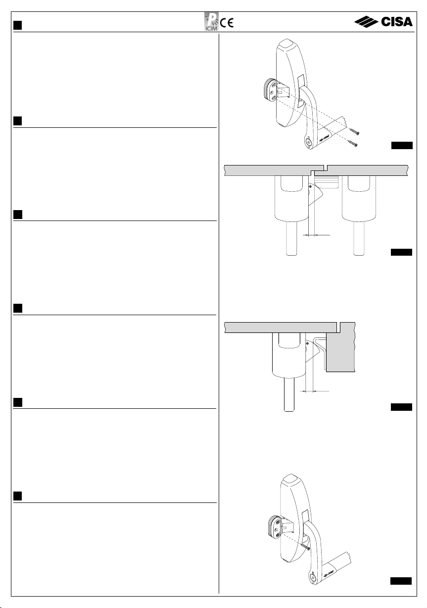
FINAL ASSEMBLY CHECK:
Check the correct operation of the panic exit device:
a) Bar:
after being pressed, it should automatically return to its initial position. When
pressed from the secondary casing side (door hinge side), the latch-bolt should
withdraw all the way in - just as if it were pushed from the main casing side (door leaf
side).
b) Anti-picking device:
with the door closed, the latch-bolts must be firmly engaged (if
manually actuated they should not withdraw), they should only move back if the bar or
the outside operation device - if any - are actuated.
c)
Grease the matching area in the panic exit device locking points between the latch-bolt
and the striker with mineral grease having a working temperature suitable for the
current conditions of use.
MAINTENANCE: See the maintenance instructions in the literature to be delivered to the
end user.
VERIFICATION DU MONTAGE FINAL:
Vérifier le fonctionnement de la poignée anti-panique:
a) Barre:
en fin depoussée, elle doitrevenir librement et de façon nette dans sa position initiale.
En la pressant du côtédu boîtier secondaire (côtéde la charnière de la porte), le pêne doit
revenir jusqu’à bout de la course, comme lorsqu’on le presse du côtédu coffre principal
(côtéde la butée de la porte).
b) Anti-effraction:
quand la porte est fermée, le pêne doit toujours être bloqué, il ne doit pas
reculer sous la pression des mains mais uniquement sous la pression de la barre et de la
commande extérieure (si elle est prévue).
c)
Lubrifier la zone de contact au niveau des points de fermeture de la poignée entre le pêne
et la gâche avec de la graisse minérale ayant une température d’utilisation appropriée aux
conditions de travail.
ENTRETIEN: Voir les instructions pour l’entretien àremettre àl’utilisateur.
VERIFICACIÓN DEL MONTAJE FINAL:
Verifique el funcionamiento de la barra:
a) Barra:
luego de ser apretada, debe regresar libremente y con fuerza a la posición inicial.
Apretándola en el lado del cofre secundario (lado de la bisagra de la puerta), el pestillo
debe retornar completamente, al igual que si se la aprieta en el lado del cofre principal
(lado del batiente de la puerta).
b) Anti-picking:
con la puerta cerrada, el pestillo debe estar bloqueado (no deve retroceder
cuandose lo empujacon las manos);debe retroceder sólo accionando la barra y-si está
previsto- el mando externo.
c)
Lubrique la zona de contacto en los puntos de cierre de la barra -entre el pestillo y el
batiente-con grasa mineralcon una temperaturade empleo adecuadaa las condiciones
de uso.
MANTENIMIENTO:Consulte las recomendacionesparaelmantenimiento, suministradas
al usuario.
VERIFICA MONTAGGIO FINALE:
Verificare il funzionamento del maniglione:
a) Barra:
dopo essere stata premuta deve tornare liberamente e con decisione nella posizione
iniziale. Premendola dal lato scatola secondaria (lato cerniera porta) lo scrocco deve rientrare
completamente come premendola dal lato scatola principale (lato battuta porta).
b) Antiscasso:
aportachiusa lo scrocco deve risultare bloccato(nondevearretrare se spinto con
le mani), deve arretrare solo azionando la barra e (se previsto) il comando esterno.
c)
Lubrificarela zona di contattoneipunti di chiusura delmaniglione tra lo scroccoe la bocchetta
congrasso minerale che abbiaunatemperatura di impiego adeguataalle condizioni di utilizzo.
MANUTENZIONE:
Vedi foglio di raccomandazioni per la manutenzione da consegnare all’utilizzatore.
MONTAGE-ABSCHLUSSPRÜFUNG:
Einwandfreies Funktionieren des Türdrückers folgendermaßen prüfen:
a) Stange:
- Nachdem sie gedrückt wird, muss sie sofort wieder in die Anfangsposition
zurückkehren. - Wenn sie auf der Nebenkasten-Seite (Türscharnier-Seite) gedrückt
wird, muss die Falle vollständig eingetreten sein, gleich wie wenn sie auf der Seite des
Hauptkastens (Türanschlagseite) gedrückt wird.
b) Einbruchsicherung:
die Falle muss bei geschlossener Tür gesperrt sein (sie darf auch
nicht zurücktreten, wenn sie mit den Händen gedrückt wird), sie darf nur zurücktreten,
wenn die Stange und (wenn vorgesehen) der Griff auf dem Aussenschild betätigt wird.
c)
Den Kontaktbereich der Schliessungsstellen des Türdrückers zwischen Falle und
Beschlagmit Mineralfett, dasdiedemEinsatzentsprechenden Temperatureigenschaften
aufweist, schmieren.
WARTUNG: Siehe Wartungshinweise, die dem Benutzer ausgehändigt werden.
CONTROLE VAN DE EINDMONTAGE:
De goede werking van het anti-paniekslot nagaan:
a) Duwstang:
moet na het induwen weer vrij en snel in de beginpositie gaan. De schoot
moet, zowel door het duwen van de duwstang aan de kant van de secundaire slotkast
(zijde scharnier), als aan de kant van de hoofdkast (zijde deuraanslag), volledig
ingetrokken worden.
b) Inbraakbeveiliging:
met gesloten deur moet de schoot geblokkeerd blijven (moet niet
met de handen naar binnen geduwd kunnen worden), en moet alleen door het duwen
op de duwstang, en (indien van toepassing) door het werken op de externe bediening,
ingetrokken worden.
c)
De contactvlakken van het anti-paniekslot, tussen de schoot en de schootplaat met een
geschikt mineraalvet insmeren.
ONDERHOUD: Zie onderhoudsinstructies voor de eindgebruiker.
This manual suits for next models
1
Table of contents
Other CISA Door Lock manuals
Popular Door Lock manuals by other brands

Hydro
Hydro WICONA WICLINE evo Hardware installation

Extel
Extel WECA 109059 SER.R1 Installation and user guide

hager
hager 3400 Series Electrical Specifications & Supplemental Instructions

Kwikset
Kwikset Combo 690 CP installation instructions

Interflex
Interflex IF-80x manual

eku
eku CLIPO 35 GPK quick start guide

ZKTeco
ZKTeco AL10B Installation instruction

Assa Abloy
Assa Abloy Lockwood Standalone User manual and instructions

Extel
Extel WECA 109058 Installation and operation manual

Mercury
Mercury BR20 Installation and Maintenance

Iseo
Iseo Push Sirena Assembling and maintenance instructions

miseno
miseno Elkton MLK1012-MLK1238-SB instructions