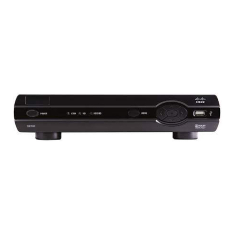
Cisco ISB7000 User manual

Cisco ISB7000 Series
High-Denition
IP Set-Tops
Energy Star V3
Installation Manual

2

3
Contents
Notice for Installers ..........................................................................................................4
IMPORTANT SAFETY INSTRUCTIONS..............................................................................4
Change the Way You Watch TV .......................................................................................6
Identify Your Set-Top .......................................................................................................6
Safety First.......................................................................................................................7
Serial Number..................................................................................................................7
In This Manual..................................................................................................................7
Open Source GNU GPL Statement..................................................................................7
Front Panel.......................................................................................................................8
Back Panel .......................................................................................................................9
Connecting the Set-Top.................................................................................................10
ISB7005 Wireless Network Connection.........................................................................11
Connection for ISB7005 Wireless Set-Top ....................................................................12
Connecting the Wireless Access Point to the Wireless Gateway...................................13
Pairing the Wireless Access Point and Set-Top .............................................................13
Connecting to the In-Home Network.............................................................................14
Connections for a High-Denition TV (HDTV)................................................................15
Connections for a Standard-Denition TV (SDTV) .........................................................16
Connections for a VCR or DVD Recorder.......................................................................17
Connecting to an HDTV with an HDMI Connector..........................................................18
Connecting to an HDTV with a DVI Connector ...............................................................19
Connecting to an HDTV with Component (YPbPr) Connectors......................................20
Connecting to an SDTV with Component (YPbPr) Connectors......................................21
Connecting to an SDTV with an S-Video Connector......................................................22
Connecting to an SDTV with an RCA-Type Connector ..................................................23
Connecting to an SDTV with a Coaxial Cable.................................................................24
Connecting to a Home Theater System with Component (YPbPr) Connectors .............25
Connecting to a Stereo VCR or DVD Recorder (optional) ..............................................26
Troubleshooting .............................................................................................................27
Avoid Screen Burn-In.....................................................................................................28
Frequently Asked Questions ..........................................................................................29
Picture Formats..............................................................................................................30
Index..............................................................................................................................31
Compliance Information .................................................................................................33

4
Power Source Warning
A label on this product indicates the correct power source for this
product. Operate this product only from an electrical outlet with
the voltage and frequency indicated on the product label. If you are
uncertain of the type of power supply to your home or business,
consult your service provider or your local power company.
The AC inlet on the unit must remain accessible and operable at
all times.
Ground the Product
WARNING: Avoid electric shock and re hazard! If this
product connects to cable wiring, be sure the cable system
is grounded (earthed). Grounding provides some protection
against voltage surges and built-up static charges.
Protect the Product from Lightning
In addition to disconnecting the AC power from the wall outlet,
disconnect the signal inputs.
Verify the Power Source from the
On/O Power Light
When the on/o power light is not illuminated, the apparatus may
still be connected to the power source. The light may go out when
the apparatus is turned o, regardless of whether it is still plugged
into an AC power source.
Eliminate AC Power/Mains Overloads
WARNING: Avoid electric shock and re hazard! Do
not overload AC power/mains, outlets, extension cords, or
integral convenience receptacles. For products that require
battery power or other power sources to operate them,
refer to the operating instructions for those products.
1) Read these instructions.
2) Keep these instructions.
3) Heed all warnings.
4) Follow all instructions.
5) Do not use this apparatus near water.
6) Clean only with dry cloth.
7) Do not block any ventilation openings. Install in accordance
with the manufacturer’s instructions.
8) Do not install near any heat sources such as radiators, heat
registers, stoves, or other apparatus (including ampliers)
that produce heat.
9) Do not defeat the safety purpose of the polarized or
grounding-type plug. A polarized plug has two blades with
one wider than the other. A grounding-type plug has two
blades and a third grounding prong. The wide blade or the
third prong are provided for your safety. If the provided plug
does not fit into your outlet, consult an electrician for
replacement of the obsolete outlet.
10) Protect the power cord from being walked on or pinched
particularly at plugs, convenience receptacles, and the point
where they exit from the apparatus.
11) Only use attachments/accessories specified by the
manufacturer.
12) Use onlywiththecart,stand,tripod,bracket, ortable
specified by the manufacturer, or sold with the
apparatus. When a cart is used, use caution when
moving the cart/apparatus combination to avoid injury from
tip-over.
13) Unplugthisapparatusduringlightningstorms orwhenunused
for long periods of time.
14) Refer all servicing to qualied service personnel. Servicing
is required when the apparatus has been damaged in any
way, such as a power-supply cord or plug is damaged, liquid
has beenspilledorobjectshave fallenintotheapparatus,the
apparatus has been exposed to rain or moisture, does not
operate normally, or has been dropped.
IMPORTANT SAFETY INSTRUCTIONS
Notice for Installers
The servicing instructions in this notice are for use by qualied service personnel only. To reduce the risk of electric shock, do not perform
any servicing other than that contained in the operating instructions, unless you are qualied to do so.
20080814_Installer800
Note to System Installer
For this apparatus, the cable shield/screen shall be grounded as close as practical to the
point of entry of the cable into the building. For products sold in the US and Canada, this
reminder is provided to call the system installer's attention to Article 800-93 and Article
800-100 of the NEC (or Canadian Electrical Code Part 1), which provides guidelines for
proper grounding of the cable shield.
This symbol is intended to alert you that uninsulated voltage within
this product may have sufficient magnitude to cause electric
shock.Therefore, it is dangerous to make any kind of contact with any
inside part of this product.
Ce symbole a pour but d’alerter toute personne qu’un contact avec
une pièce interne de ce produit, sous tension et non isolée, pourrait
être suffisant pour provoquer un choc électrique. Il est donc
dangereux d’être en contact avec toute pièce interne de ce produit.
CAUTION: To reduce the risk of electric shock, do not remove cover (or
back). No user-serviceable parts inside. Refer servicing to qualified service
personnel.
WARNING
T
O PREVENT FIRE OR ELECTRIC SHOCK, DO NOT EXPOSE THIS UNIT
TO RAIN OR MOISTURE.
This symbol is intended to alert you of the presence of important
operating and maintenance (servicing) instructions in the literature
accompanying this product.
Ce symbole a pour but de vous avertir qu’une documentation
importante sur le fonctionnement et l’entretien accompagne ce
produit.
5
Protect from Exposure to Moisture
and Foreign Objects
WARNING: Avoid electric shock and re hazard! Do
not expose this product to dripping or splashing liquids,
rain, or moisture. Objects lled with liquids, such as vases,
should not be placed on this apparatus.
WARNING: Avoid electric shock and fire hazard!
Unplug this product before cleaning. Do not use a liquid
cleaner or an aerosol cleaner. Do not use a magnetic/static
cleaning device (dust remover) to clean this product.
WARNING: Avoid electric shock and re hazard! Never
push objects through the openings in this product. Foreign
objects cancauseelectrical shortsthatcanresultinelectric
shock or re.
Service Warnings
WARNING: Avoid electric shock! Do not open
the cover of this product. Opening or removing the cover
may expose you to dangerous voltages. If you open the
cover, your warranty will be void. This product contains
no user-serviceable parts.
Check Product Safety
Upon completion of any service or repairs to this product, the service
technician must perform safety checks to determine that this product
is in proper operating condition.
Protect the Product When Moving It
Always disconnect the power source when moving the apparatus
or connecting or disconnecting cables.
20110316_IP_NoTuner_Safety
Handling Disposable Batteries
This product may contain disposable batteries. Heed the following
warning and follow the Battery Safety and Battery Disposal
instructions below.
WARNING: There is danger of explosion if the battery
is mishandled or incorrectly replaced. Replace only with
the same type of battery. Do not disassemble it or attempt
to recharge it outside the system. Do not crush, puncture,
dispose of in re, short the external contacts, or expose to
water or other liquids. Dispose of the battery in accordance
with local regulations and instructions from your service
provider.
Battery Safety
• Insert batteries correctly. There may be a risk of explosion if
the batteries are incorrectly inserted.
• Do not attempt to recharge ‘disposable’ or ‘non-reusable’
batteries.
• Please follow instructions provided for charging
‘rechargeable’ batteries.
• Replace batteries with the same or equivalent type that we
recommend.
• Do not expose batteries to excessive heat (such as sunlight
or re).
• Do not expose batteries to temperatures above 100°C
(212°F).
Battery Disposal
• The batteries may contain substances that could be harmful
to the environment.
• Recycle or dispose of batteries in accordance with the battery
manufacturer’s instructions and local/national disposal and
recycling regulations.
• The batteries may contain perchlorate, a known hazardous
substance, so special handling and disposal of this product
might be necessary. For more information about perchlorate
and best management practices for perchlorate-containing
substance, see www.dtsc.ca.gov/hazardouswaste/
perchlorate
Provide Ventilation and
Select a Location
•Remove all packaging material before applying power to the
product.
•Do not place this apparatus on a bed, sofa, rug, or similar
surface.
•Do not place this apparatus on an unstable surface.
•Do not install this apparatus in an enclosure, such as a
bookcase or rack, unless the installation provides proper
ventilation.
•Do not place entertainment devices (such as VCRs or DVDs),
lamps, books, vases with liquids, or other objects on top of
this product.
•Do not block ventilation openings.
Operating Environment
The set-top is designed for operation indoors with a temperature
range from 32° to 104° F (0° to 40°C). Each set-top should have
adequate spacing on all sides so that the cooling air vents on the
chassis are not blocked.
IMPORTANT SAFETY INSTRUCTIONS,continued

6
Change the Way You Watch TV
Welcome to Internet Protocol Television (IPTV). The Cisco®ISB7000 Series High-Denition IP Set-Tops
bring a rich, new set of interactive services directly to you through your TV and your in-home IP network.
The set-top uses the existing in-home coaxial cable wiring and connects to most entertainment devices.
Available services may include some or all of the following features:
• Digital Video Recorder (DVR) – Allows you to record your favorite programs so that you can still
go to your friend’s house for dinner and not miss your favorite TV show
• Pause Live TV – Allows you to pay for the pizza and come back to the show where you left it.
(Applies to DVR models only)
• High-Denition (HD) – Provides crystal-clear pictures and sound when compared to standard-
denition – you won’t want to watch television any other way once you’ve experienced HD
• Video-On-Demand (VOD) – Gives you access to a robust library of movies and programs that
you can watch – when you want to watch them
Note: Contact your service provider to nd out if the DVR, HD, or VOD services are available and to
activate the services.
Identify Your Set-Top
Your installation manual covers the following models of set-tops. Use the following information to
identify your model.
• ISB7000 set-top – TV set-top that supports high-denition (HD) and standard-denition (SD)
video decoding. Supports 480i, 720p, and 1080i content. Uses Ethernet over CAT-5 or HPNAv3
in-home networking over coaxial or twisted-pair
• ISB7005 set-top – The ISB7005 is the same as the ISB7000 but with a wireless feature and no
RF to wall connector
• ISB7030 set-top – The ISB7030 is the same as the ISB7000 but with a 320 GB hard disk drive
• ISB7031 set-top – The ISB7031 is the same as the ISB7030 but without HPNA and without RF
to TV connector
• ISB7050 set-top – The ISB7050 is the same as the ISB7000 but with a 500 GB hard disk drive
• ISB7080 set-top – The ISB7080 is the same as the ISB7000 but with a 1 TB hard disk drive
• ISB7100 set-top – The ISB7100 is the same as the ISB7000 but without optional connectors
• ISB7150 set-top – The ISB7150 is the same as the ISB7050 but without optional connectors
POWER LINK HD RECORD MENU
OK
OK
OK
ISB
7000
ISB7000 / ISB7100
ISB7005
POWER LINK HD RECORD MENU
OK
OK
OK
ISB
7005
ISB7030 / ISB7031 / ISB7050 / ISB7080 / ISB7150
OK
OK
OK
ISB
7031
T15239

7
Safety First
Before using the set-top, read the Important Safety Instructions section of this manual.
Serial Number
At times your service provider may ask for the serial number. To nd the serial number for your set-
top, look on the bottom of the set-top for the label. The serial number is a 9-digit numeric code to
the right of the letters “S/N” on the label.
Use the space provided here to record the serial number: _______________________________
In This Manual
This manual covers the information you need to connect your set-top to both your in-home IP
network and your entertainment system. The manual also outlines certain safeguards and installation
information. The safety information contained in this manual was developed and provided solely by
the set-top manufacturer, Cisco Systems, Inc.
Open Source GNU GPL Statement
Cisco ISB7000 set-tops contain(s), in part, certain free/open source software (“Free Software”) under
licenses which generally make the source code available for free copy, modication, and redistribution.
Examples of such licenses include all the licenses sponsored by the Free Software Foundation (e.g. GNU
General Public License (GPL), GNU Lesser General Public License (LGPL), Berkeley Software Distribution
(BSD), the MIT licenses and dierent versions of the Mozilla and Apache licenses). To nd additional
information regarding the Free Software, including a copy of the applicable license and related
information, please go to: (i) for North America http://www.cisco.com/web/consumer/support/
open_source.html, or (ii) for outside North America http://www.cisco.com/web/consumer/support/
open_source.html#~international. Once at the site, search for the product listing and click on the
related items identied. If you have any questions or problems accessing any of the links, please contact:
spvtg-external-opensource-r[email protected].

8
Front Panel
1 Power Turns the set-top on or places it in standby. To restart the set-top,
press and hold the POWER button for 10 seconds. The LED is green
2 Model Number Identies the model number of your set-top as ISB7000, ISB7005,
ISB7030, ISB7031, ISB7050, ISB7080, ISB7100, or ISB7150
3 Link Indicates network link status. The LED is green
4 HD Indicates the set-top is set to a resolution of 720p or 1080i. The LED is
blue
5 Record Indicates that a recording is in progress. The LED is red
6 IR Sensor Receives the infrared signal from the remote control. The sensor is
behind the front panel
7 Menu Accesses the on-screen menu
8 Arrow Keys Accesses on-screen services (such as the on-screen guide, video-on-
demand, or pay-per-view) and navigates menus
9 OK Selects the current item
10 USB Port USB connector (optional)
Note: This illustration may vary from the actual product.
OK
OK
OK
ISB7030
T142553 4 5 76 108921
CAUTION:
Your set-top may be equipped with a hard disk drive to store programs that
you record and to allow you to rewind and pause live TV. Any time the set-
top is powered on (power LED is illuminated) or a recording is in progress
(the record LED is illuminated), the hard disk drive is in use.
If you need to move the set-top, complete the following steps to allow the
hard disk drive to shut down properly. First, make sure that no recording is
in progress (record LED is o). Then, turn o power by pressing the Power
key. Finally, unplug the unit and wait 10 seconds for the hard disk drive to
spin down (stop). At this point, the unit can be moved safely.
You should handle this product with the same level of care you would use
when handling other electronics containing a hard disk drive, such as a
laptop computer or other hard disk drive-equipped devices.

9
Back Panel
1 To Wall (Video In) Connect the set-top to in-house coaxial wiring, if applicable. (optional)
2 To TV (Video Out) Connect to TV. You must set the channel on your TV to the channel
designated by your service provider (usually channel 3). Contact your
service provider for the channel information (optional)
3 Network Connect to the Ethernet (CAT-5) network at your home, if applicable
4 eSATA Port Connect external SATA equipment approved by your service provider
to this port (optional)
5 YPbPr Connect the set-top to the component video input (YPbPr) on your
HDTV or SDTV. See pages 15 and 16 for more information
6 S-Video Connect an S-Video cable to send an S-Video signal to your TV, VCR, or
DVD recorder. This signal is standard-denition but higher quality than
other standard-denition TV connections. See page 17 for more
information (optional)
7 Video Out Connect to composite input on your HDTV or SDTV
Note: Two video output connectors are provided. Typically, one output
is connected to the TV, and the other output is used to connect to a
home theater system, DVD recorder, or VCR
8 Audio Out (L/R) Connect RCA-type cables to Audio Out to send analog audio signals
(left and right) to a TV with stereo inputs or to a stereo amplier.
Note: Two sets of audio out connectors are provided. Typically, one set
of outputs is connected to the TV, and the other set is used to connect
to a home theater system, DVD recorder, VCR, or wireless headphones
9 Optical Connect an optical cable to send a digital audio signal to a surround-
sound system or other digital audio device
10 HDMI Connect an HDTV HDMI™(High-Denition Multimedia Interface) cable
from the HDTV to the HDMI port. HDMI supports both digital audio and
video. See page 15 for more information
11 USB Port Connects to external USB equipment approved by your service
provider (optional)
12 Power Connect the DC output of the AC power adapter (provided) to deliver
power to the set-top. Use only the AC power adapter provided with
the set-top
Note: This illustration may vary from the actual product.
T14256
Pb Y
Pr VIDEO
OUT
AUDIO
OUT
TO TV
(VIDEO OUT)
TO WALL
(VIDEO IN)
LR
NETWORK eSATA OPTICAL POWERUSBS-VIDEO
21 3 4 6 9 11
10 125 87

10
Because the connections
for a high-denition (HD)
or standard-denition (SD)
TV are dierent, you must
determine if your TV is HD
or SD. Your TV must
receive HD signals for
you to enjoy the benets
of HDTV. Refer to the manual that came with your TV for more information.
See page 30 for more information on picture formats.
Make one of the following connections for your home network:
• If your home network uses coaxial cable, use the TO WALL connector on the
set-top. See page 14.
• If your home network uses twisted pair cable (phoneline wiring), use the TO
WALL connector on the set-top and an adapter that converts twisted pair to
coaxial. See page 14.
• If your home network uses Ethernet (CAT-5) cable, use the NETWORK
connector on the set-top. See page 14.
Connecting the Set-Top
To connect your set-top to your network and home entertainment devices, complete these steps.
Identify the additional consumer
electronic devices you will
connect to the set-top and TV.
See pages 18 through 26 and
refer to the owner’s manual for
the device.
Plug the set-top and the TV into an AC power source that is not controlled by a
switch.
Make the connections for your TV, VCR, and DVD recorder as follows:
• If you are using an HDTV, see page 15 and the connection diagrams in this
manual.
• If you are using a standard-denition TV, see page 16 and the connection
diagrams in this manual.
• If you want to record some programs on VCR tape or DVD, see page 17
and the connection diagrams in this manual.
1
2
3
5
4
Home Theater
OtherDVDVCR
9
16 4
3
or

11
ISB7005 Wireless Network
Connection
The ISB7005 set-top allows for easy and secure setup of
a wireless home network. The signal strength indicator on
the front panel of the set-top indicates the strength of
the wireless connection.
The set-top must be paired with the wireless access
point for the wireless connection to be established.
See page 13 for more information.
Wireless
LEDs Set-top Operational Status
Five green bars indicate the wireless signal is excellent. The video quality is good.
Four green bars indicate the wireless signal is very good. The video quality is good.
Three green bars indicate the wireless signal is good. The video quality is good.
You must obtain three or more green bars at initial installation.
Two green bars indicate the wireless signal is fair. The video quality is good.
Two red bars indicate the wireless signal is weak. The video quality may be poor.
The STB should be re-oriented to achieve a better wireless signal.
One red bar indicates the wireless signal is very weak. No video can be displayed.
The receiver must be re-oriented to achieve a better wireless signal.
This indicates no wireless connectivity.
T14822
POWER LINK HD
ISB
7005
Signal Strength Indicator

12
Connection for ISB7005 Wireless Set-Top
The ISB7005 set-top allows for easy and secure establishment of a wireless home network. The
signal strength indicator on the front panel of the set-top allows you to identify the strength of your
wireless connection.
ISB7005
POWER LINK HD RECORD MENU
OK
OK
OK
ISB
7005
T14706
Signal Strength
Indicator
1. Plug the set-top power supply into an AC power supply that is not controlled by a switch.
2. Plug the power adapter into the set-top.
3. Press the power button on the remote control or the set-top.
Note: The signal indicator lights may ash for a few minutes when power is rst applied. Do not
unplug the set-top.

13
1Wireless LED
2Wi-Fi Protected Setup (WPS) button
3Wi-Fi Protected Setup (WPS) LED
4Ethernet LED
5Power LED
Connecting the Wireless Access Point to the Wireless
Gateway
1.Connect the 12 VDC Power Supply
plug on the access point to the wall
power outlet. Use only the power
adapter provided with the product.
2. Connect the power plug to the power
receptacle on the wireless access point.
3. Connect one end of the RJ-45
Ethernet cable to the Ethernet port on
the wireless access point.
4. Connect the other end of the RJ-45
Ethernet cable to an available Ethernet
port on your wireless gateway.
T14853
1
2
4
3
5
T14854
12VDC
Reset
Ethernet
1
2
3
Note: This illustration may vary from the actual product.
1Ethernet Port Connects the Wireless Access Point to a
wireless gateway
2Reset Restores factory default settings when held
for more than 5 seconds
3Power Connects device to the external 12 VDC
power supply
Note: This illustration may vary from the actual product.
T14961
Power Receptacle
12VDC
Reset
12VDC
Reset
Ethernet
RJ-45
Cable
To Wall Power Outlet
Wireless
Gateway
Ethernet Port
Pairing the Wireless Access Point and Set-Top
1. Press the OK button on the set-top.
2. Press the WPS button on the wireless access point.

14
Connecting to the In-Home Network
The following diagrams illustrate examples of the connections you can use to connect your set-
top to your in-home network. Contact your service provider for the recommended connection
method for your home. (This section does not apply to the ISB7005; see Connection for ISB7005
Wireless Set-Top on page 12.)
Notes:
• The in-home coaxial and phoneline wiring networks use HomePNA 3.1 technology.
• The illustrations below may vary from the actual product.
P
P
TO WALL
(VIDEO IN)
TO TV
(VIDEO OUT)
NETWORK eSATA
TO WALL
(VIDEO IN)
TO TV
(VIDEO OUT)
NETWOR
K
TO WALL
(VIDEO IN)
TO TV
(VIDEO OUT)
NETWOR
K
T14257
Coaxial
In-Home
Coaxial
Network
Wall
Phoneline
OR
Wall
Adapter
CAT-5
OR
In-Home
Phoneline
Network
In-Home
CAT-5
Network
Wall

15
Connections for a High-Denition TV (HDTV)
To use the set-top with an HDTV, you must make one of the following connections to view the HD
content. Refer to the owner’s manual for your TV and the cabling diagrams in this manual for more
detailed connection information.
Although all connections provide you with quality service, we list the connections in our
recommended order.
Notes:
• The labeling on your set-top or HDTV may vary slightly from the illustrations shown below.
• Some cables shown in the connection diagrams may not be included with this set-top.
• Set the HD mode and select the output video format (480i, 720p, 1080i) on the set-top.
See page 30 for more information on picture formats.
Some HDTVs have a High-Denition Multimedia
Interface (HDMI) connector. The HDMI connector
provides both a digital video and audio connection.
See the connection diagram on page 18 for an
example.
Note: The HDMI port on the TV must support
high-bandwidth digital content protection (HDCP).
HDTV
Connections
The HDMI connector can provide the connection
to an HDTV with a DVI input. If your HDTV has a
Digital Visual Interface (DVI) connector, you need
an HDMI-to-DVI adapter, and a separate audio
connection (either L/R or optical audio).
Note: The DVI port on the TV must support
high-bandwidth digital content protection (HDCP).
See the connection diagram on page 19 for an
example.
Use One of These Required
Connections to an HDTV
DVI
Set-Top
Connections
The YPbPr (red, blue, and green) connectors
provide high-denition component video signals
to an HDTV, and a separate audio connection
(either L/R or optical audio).
See the connection diagram on page 20 for an
example.
Pr
Pb
Y
Audio/VideoVideoVideo
DVI HDMIYPbPr
Pr
Pb Y
Some HDTVs have only RGB or RGB-HV
connectors. If you have one of these HDTVs,
you need a Component-to-RGB adapter, and
you need a separate audio connection. B
G
V
H
R
Pr
Pb Y
Adapter Needed
Adapter Needed
Video
RGB
Audio
LR
AUDIO
OUT
LR
AUDIO
OUT
LR
OPTICAL
OPTICAL
INPUT
LR
Audio
AUDIO
OUT
LR
OPTICAL
OPTICAL
INPUT
LR
Audio

16
Connections for a Standard-Denition TV (SDTV)
When using the set-top with an SDTV, you must make one of the following connections to view
content. Some SDTVs may not have all these connections. Refer to the owner’s manual for your TV
and the cabling diagrams in this manual for more detailed information.
Although all connections provide you with quality service, we list the connections in our
recommended order.
Notes:
• The labeling on your set-top or SDTV may vary slightly from the illustrations shown below.
• Some cables shown in the connection diagrams may not be included with this set-top.
The YPbPr (red, blue, and green) connectors
can provide standard-denition component
video signals to an SDTV. A separate audio
connection is also needed.
Note: To connect YPbPr to an SDTV, you
must select the output video format. See
page 30 for more information on picture formats.
See the connection diagram on page 21 for
an example.
SDTV
Connections
Use One of These Required
Connections to an SDTV Set-Top
Connections
The S-Video connection provides an optimal
video connection to SDTVs. A separate audio
connection is also needed.
See the connection diagram on page 22 for
an example.
Audio/Video
The Video Out connector provides a video
connection to an SDTV. A separate audio
connection is also needed.
See the connection diagram on page 23 for
an example.
S-VideoTo TV (Video Out) Video Out
TO TV
(VIDEO OUT)
CABLE IN/
ANT IN
S-VIDEO
IN
VIDEO
OUT
VIDEO
IN
LR
LR
Pr
Pb
Y
LR
YPbPr
Audio VideoAudio Video
The To TV (Video Out) connector provides both
a video and audio connection to an SDTV.
See the connection diagram on page 24 for
an example.
Audio Video
Pr
Pb Y
AUDIO
OUT
LR
AUDIO
OUT
LR
AUDIO
OUT
LR
S-VIDEO
IN

17
Connections for a VCR or DVD Recorder
When using the set-top with a VCR or DVD recorder, you must make one of the following
connections to view content.
Although all connections provide you with quality service, we list the connections in our
recommended order.
Notes:
• The labeling on your set-top, VCR, or DVD recorder may vary slightly from the illustrations shown
below.
• Some cables shown in the connection diagrams may not be included with this set-top.
For VCRs or DVD recorders with Video In and
Left and Right audio connectors, use the Video
Out and the Audio Out connectors (Left and
Right) on the set-top.
See the connection diagram on page 26 for an
example.
VCR/DVD Recorder
Connections
Use One of These Optional
Connections to a VCR or DVD Recorder Set-Top
Connections
VCR/DVD Recorder
Audio Video
For VCRs or DVD recorders with S-Video In
and Left and Right audio connectors, use the
S-Video and the Audio Out Left and Right
connectors on the set-top.
Audio Video
S-VIDEO
IN
VIDEO
OUT
VIDEO
IN
LR
LR
AUDIO
OUT
LR
AUDIO
OUT
LR
S-VIDEO
IN

18
Connecting to an HDTV with an HDMI Connector
Cable Used in this Conguration
• 1 HDMI Cable
Notes:
• The HDMI port on the TV must support high-bandwidth digital content protection (HDCP).
• The HDMI interface supports Dolby™Digital 5.1 audio.
WARNING:
Electric shock hazard! Unplug all electronic devices before connecting or
disconnecting any device cables to the set-top.
Set-Top
T14738
Pb
Y
P
r
V
IDEO
OU
T
AUDIO
OU
T
T
O WALL
(
VIDEO IN
)
T
O TV
(
VIDEO OUT
)
L
R
NETWORK
e
SAT
A
OPTICAL
P
OWER
U
SBS-VIDEO
Back of HDTV
HDMI
AUDIO
CENTER
CHANNEL IN
AUDIO IN
DVI/HDCP
ANT (75 )
INOUT
LR
ANT-1
HD 2
Y
OUT
ANT-2
PB
PR
L
R
VIDEO
L/
MONO
R
L/
MONO
R
AUDIO
IN
ON OFF
IN
HD 1
S-VIDEO
VIDEO Y
PB
PR
L
R
AUDIOAUDIO

19
Connecting to an HDTV with a DVI Connector
Cables Used in this Conguration
• 1 HDMI-to-DVI Cable or 1 HDMI Cable and 1 HDMI-to-DVI Adapter
• 1 Audio Left/Right Cable (You can also use an optical cable [indicated by the dotted line] instead
of the Audio Left/Right Cable as shown in the diagram, dependent upon your TV’s capabilities.)
Notes:
• The DVI port on the TV must support high-bandwidth digital content protection (HDCP).
• When you connect the HDMI connector to the DVI connector on your HDTV, you need an
HDMI-to-DVI adapter and a separate audio connection.
WARNING:
Electric shock hazard! Unplug all electronic devices before connecting or
disconnecting any device cables to the set-top.
Set-Top
Pb
Y
P
r
V
IDEO
OU
T
AUDIO
OU
T
T
O WALL
(
VIDEO IN
)
T
O TV
(
VIDEO OUT
)
L
R
NETWORK
e
SAT
A
OPTICAL
P
OWER
U
SBS-VIDEO
T14739
AUDIO
OUT
Back of HDTV
AUDIO
CENTER
CHANNEL IN
ANT (75 )
INOUT
ANT-1
HD 2
Y
OUT
ANT-2
PB
PR
L
R
VIDEO
L/
MONO
R
L/
MONO
R
AUDIO
IN
ON OFF
IN
HD 1
S-VIDEO
VIDEO Y
PB
PR
L
R
AUDIOAUDIO
DVI/HDCP
IN
AUDIO IN
DVI/HDCP
LR
OPTICAL
INPUT
OR

20
Connecting to an HDTV with Component (YPbPr)
Connectors
Cables Used in this Conguration
• 1 Component Video Cable (YPbPr)
• 1 Audio Left/Right Cable (You can also use an optical cable [indicated by the dotted line] instead
of the Audio Left/Right Cable as shown in the diagram, dependent upon your TV’s capabilities.)
WARNING:
Electric shock hazard! Unplug all electronic devices before connecting or
disconnecting any device cables to the set-top.
Set-Top
T14740
Pb
Y
P
r
V
IDEO
OU
T
AUDIO
OU
T
T
O WALL
(
VIDEO IN
)
T
O TV
(
VIDEO OUT
)
L
R
NETWORK
e
SAT
A
OPTICAL
P
OWER
U
SBS-VIDEO
Pb Y
Pr AUDIO
OUT
Back of
HDTV
HDMI
AUDIO
CENTER
CHANNEL IN
AUDIO IN
DVI/HDCP
ANT (75 )
INOUT
LR
ANT-1
HD 2
Y
OUT
ANT-2
PB
PR
L
R
VIDEO
L/
MONO
R
L/
MONO
R
AUDIO
IN
ON OFF
S-VIDEO
VIDEO
AUDIO
IN
HD 1
Y
PB
PR
L
R
AUDIO
OPTICAL
INPUT
OR
Other manuals for ISB7000
1
Table of contents
Other Cisco Set-top Box manuals

Cisco
Cisco RNG150 User manual

Cisco
Cisco PDS3241 User manual

Cisco
Cisco EXPLORER 4640HDC User manual

Cisco
Cisco EXPLORER 4640HDC User manual

Cisco
Cisco Z870DVB User manual

Cisco
Cisco Explorer 4700 User manual

Cisco
Cisco Explorer 1640HDC User manual

Cisco
Cisco Explorer 8640HDC User manual

Cisco
Cisco C2130U User manual

Cisco
Cisco ITV7900 User manual

Cisco
Cisco CIS2000 User manual

Cisco
Cisco 1840 User manual

Cisco
Cisco IPV5000 User manual

Cisco
Cisco 8640HD User manual

Cisco
Cisco 3413DVB User manual

Cisco
Cisco PDS2100 Series User manual

Cisco
Cisco 8640HD User manual

Cisco
Cisco Explorer 3350 User manual

Cisco
Cisco Hawaiian Telcom User manual

Cisco
Cisco Explorer 8600HD Series User manual