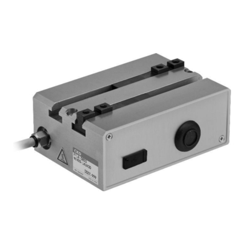
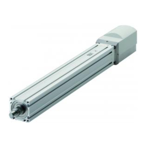
CKD FP Series User manual

389
Safety precautions
FP Series: Warnings and Cautions
Be sure to read this section before use.
Refer to "Pneumatic Cylinders I (CB-029SA)", "Pneumatic Cylinders II (CB-030SA)",
"Pneumatic Valves (CB-023SA)", "Pneumatic, Vacuum, and Auxiliary Components (CB-
024SA)", and "Fluid Control Valves (CB-03-1SA)" for general and product-specic precautions.
Although the above general catalog states that products are not applicable for equipment or
applications with direct contact with beverages/foodstus, the FP2 Series products can be
used in such applications as long as they are within the range of the product specications.
Design/selection
CAUTION
"Food Sanitation Act compliant" refers to products
with materials (resin, rubber) conforming to the
compliant of the Food Sanitation Act.
Use after confirming the structure and material,
valve structure, working fluids, and working
atmospheres of each component carefully yourself.
Depending on the model, internal parts may wear
when the valve operates. If affected, take
necessary measures such as installing a lter on
the secondary side.
If the uid is water or water drops remain inside, rust may
be generated and ow to the secondary side depending
on the model. Take necessary measures in that case.
Bearings used in cylinders contain trace amounts
of mineral oil. Within the product specifications
range, it is processed so as not to discharge, but
please carefully consider the installation location.
The protection structure and material (except lubricant)
of the 4G-FP1 Series are the same as those of
standard products. Therefore, leakage or corrosion
may occur in an environment with a high temperature
and humidity or where the product is exposed to
water. Select installation locations with care.
When using the product
CAUTION
After installation, check for leaks from pipes, for proper
wire connections and that the product is installed correctly.
Do not use the product as footing or place any
heavy objects on top of the product.
If the product has been out of use for one month or more,
perform a test run before starting the actual operation.
When hot uid ows during steam sterilization, the
valve body becomes hot, so do not touch with your
hand or body. There is a risk of burns if these coils
are touched directly.

390
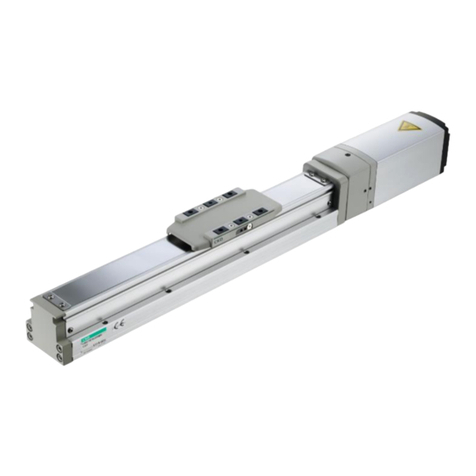
Product-specic cautions: Electric actuator EBS-M/EBR-M/EBS-L/EBR-L/EKS-L/ETS/ETV/ECS/ECV Series
Safety precautions
FP Series: Warnings/Cautions
Be sure to read this section before use.
Refer to "Electric Actuator Motorless (CB-055A)" and "Electric Actuator EBS-M/EBR-M Series
(CC-1422A)" for general and product-specific precautions.
Design/selection
Use/maintenance
Precautions for export
CAUTION
CAUTION CAUTION
Do not hit the trolley table against the stroke end.
Indicate the maintenance conditions in the device's
instruction manual.
The product's functionality may drop too low to maintain an
appropriate safety level depending on usage conditions,
working environment and maintenance status. With correct
maintenance, the product functions can be used to the fullest.
Regarding installing, setting up, and/or adjusting
the actuator, read through the instruction manual
and operate correctly.
The product is manufactured in conformity with the related
standards. Do not disassemble or modify the product.
Refer to the instruction manual of the motor mounted to the
product and control for your safety before wiring and designing.
The customer is responsible for confirming the
compatibility of CKD products with the customer's
systems, machines and equipment.
This product uses food-grade (NSF H1) lubricants.
Do not mix with other greases.
Regularly inspect the product at least two or three
times a year to check that it operates correctly.
Grease the product once every 3 months or at
100km intervals as a general guide. Note that
grease interval differs depending on the working
conditions. It is recommended to determine the
interval based on initial inspection. Refer to the
instruction manual for details.
If the product has been out of use for one month or more,
perform a test run before starting the actual operation.
The circuit board inside the product has capacitors
connected between the circuits and the metal body to
prevent damage due to static electricity. Avoid
withstand voltage and insulation resistance tests on
equipment with this product installed. If tests are done,
the product will be damaged. If necessary for the
equipment, remove the product before doing the test.
If the actuator and controller combination is
changed, be sure to confirm the programs and
parameters prior to operation.
Otherwise, there is a risk of unexpected accidents.
Products and related technologies in this catalog
The products and related technologies in this catalog are subject to US Export Administration Regulations (EAR),
and display of EAR-compliant products is marked on the product page. For export or provision of products or
related technologies subject to EAR regulations, we request that the US Export Administration Regulations (EAR)
be observed appropriately.
1. Common
1. Common
DANGER
CAUTION
Use a DC stabilized power supply (48 VDC±10% or
24 VDC±10%) for the motor, control, and input/
output circuit power supplies. Connecting directly to
the AC power supply may cause fire, explosion,
damage, etc.
Select a power supply which provides ample capacity
based on the number of installed products.
Malfunction may occur if there is no excess capacity.
(Guideline: 35...4.0A/stand, 42...5.2A/stand,
56...8.6A/base)
2. EBS-M/EBR-M Series

391
Anti-bacterial/bacteria-removing/odor removal lter
Safety Precautions
Be sure to read this section before use.Refer to "Pneumatic Components (CB-023SA)" and
"Pneumatic, Vacuum, and Auxiliary Valves (CB-024SA)" for general and product-specific
precautions. Although the above general catalog states that products are not applicable for
equipment or applications with direct contact with beverages/foodstus, the FP2 Series products
can be used in such applications as long as they are within the range of the product specications.
WARNING
The antibacterial lter has an antibacterial eect on the
bacteria attached to internal filter elements,
suppressing bacteria growth. The working uid has no
bacteria-reducing eects. *Anti-bacterial activity value,
which represents the anti-bacterial eect, is an actual
value from CKD's prescribed conditions.
The bacteria-removing lter and reduces the bacteria
in the working uid, but it does not kill all bacteria. It
also does not remove viruses. LRV, which
represents bacteria-removing effect, is an actual
value from CKD's prescribed conditions.
This product is for industrial use. Do not use in any
equipment or circuit that concerns human life.
This product exerts no inuence on performance and
a small amount of leakage is tolerable.
Ventilate well when using nitrogen gas (N2) and carbon dioxide (CO2).
This lter traps waste and bacteria in working uids and provides
clean working fluids to the secondary side. Anti-bacterial and
bacteria removing functions are not added to the working uid itself.
It cannot be used in environments containing sodium hypochlorite,
synthetic oil, organic solvents, chemicals, cutting oil, screw locking
agent, leak detection solutions, or hot water, etc., or where these
substances may come in contact with the product. For more
information on the chemical resistance of plastic bowls and
transparent cases, see page 369.
Piping load torque
Avoid piping xed with a single support, as this can
result in excessive force and lead to damage.
[Combination, module type]
Avoid applying piping load or torque to the body or pipes.
Properly check the compliant of the material against its
use conditions and environment before using this product.
Design/selection
Check the working circuit and working uid.
To prevent drop in lter performance, install the dryer, air lter and
oil mist lter on the primary side, and remove water or oil.
Installation order for anti-bacterial/bacteria-removing/odor removal lter
We recommend the use of the bacteria-removing unit as the
nal lter before the compressed air/gas contact foodstus.
Do not exceed maximum working or differential
pressure. Not observing this could damage the product
or element.
Do not ow over the max. processing ow rate.
Doing so may degrade the ltration accuracy and damage the element.
This device cannot be used as an absolute filter
(absolute degree of ltration).
Do not use where the IN/OUT pressure dierential
exceeds 0.1 MPa.
A sudden supply of fluid to the filter (such as air blow by
releasing the secondary side to the atmosphere, etc.) may
reduce the removal efficiency. In this case, install a
restriction valve on the lter's IN side to keep the pressure
difference to 0.1 MPa or less. Consult with CKD about
attaching dierential pressure gauge GA400.
High moisture levels
Install the air dryer and drain separator before the
anti-bacterial/bacteria removing lter.
If there is a lot of
moisture from the compressor, hot and highly humid air
could shorten the device's life or result in corrosion.
For compressor circuit of water lubrication method
Take measures to prevent chlorine-based
substances from entering the compressed air.
The odor removal lter uses activated carbon to apply suction
to oil vapor. Be sure to install an oil mist lter (M Series M
type) on the primary side, and remove oil mist in advance.
The odor removal lter uses suction to remove the oil
vapor in compressed air (nitrogen gas, carbon dioxide).
Activated carbon suction is not equally effective with all
substances, so that it will not completely eliminate all odors.
The odor removal lter does not have anti-bacterial
or bacteria-removing functions.
CAUTION
Series SFC3** SFC4** SFC8**
Max. torque
Nm50 50 100
Anti-bacterial
Pre
Anti-bacterial
High performance
Deodorizing
Bacteria
removing
IN OUT
Air dryer Filter Oil mist
Filter
Anti-bacterial/bacteria-
removing/odor removal
Filter

392
Mounting, installation and adjustment
Check the ow direction by arrow and connect correctly.
Securing maintenance space
Secure sucient space for maintenance and inspection.
After attaching the pipes, flush and clean them
before use.
Dirt or foreign matter remaining in the piping will deteriorate
product performance.
Check that foreign matter does not enter when
tightening pipes or ttings.
When screwing in piping or fittings, check that swarf from port
threads or sealant does not get inside. Dirt or foreign matter
remaining in the piping will deteriorate product performance.
In
particular, if swarf from the OUT side port thread on the last-
installed unit is produced, that swarf will be blown through
too. During piping, tighten at or below the torque determined in
the catalog, and then ush thoroughly before use.
Install the drain cock downward and vertically.
Piping screw-in torque
[Combination, module type]
Make sure that excessive torque is not applied on
the body and piping when piping.
[Inline]
Drain piping
The drain piping for the plastic bowl has a barbed nipple, and
can be directly installed. However, conrm that the drain cock
is closed before inserting the tube.
Do not route it vertically.
Pipe so that no lateral load is applied on the bowl. Do not
x the tube connected to the drain outlet with a lateral
load applied. If drainage is performed with a lateral load
applied, external leakage may occur.
Tightening torque of drain cock
The maximum tightening torque of the drain cock of the
plastic bowl is 0.5 N m.
Perform piping so no excessive force is applied to the product.
When piping or installing, do not apply tension, compression,
bending or external force from tubes, etc.
When supplying working uid after connecting pipes,
do not suddenly apply high pressure.
Connected piping could be dislocated and tubing could y o.
Select the appropriate piping tube.
Securely insert a tube into the push-in tting before use.
Use the width across ats of the connection part when piping.
[Inline]
In the case of Rc thread piping, apply the wrench to the
width across flats of the connection part. Do not apply it to
any other part when tightening.
Attach the maintenance label to this product to
make maintenance periods clear.
Storage
Do not store this product in a hot, humid atmosphere or
atmospheric conditions outside of the specified range for a
prolonged period of time. Resin or rubber parts could deteriorate,
and the resin element housing could become discolored.
Contact CKD when storing products exceeding specications.
CAUTION
Port thread
Tightening torque N·m
Rc1/4 6 to 8
Rc3/8 13 to 15
Prevent the generated ozone from passing through
the filter. Otherwise the filter element may be
degraded. Take care especially when using an
ozone generator (e.g., ionizer) together.
(1) Do not install in the upstream portion of the lter.
(2)
When installing downstream of the lter, stop air while static
electricity is neutralized since generated ozone may ow back.
Avoid installing this product where it is subject to direct sunlight.
If the hollow ber membrane in the bacteria-removing lter
suers oxidative degradation from ozone or ultraviolet in the
uid, it may be damaged and allow ow over to the secondary
side. Implement periodic inspections and exchange. Consult
the graph below for standard replacement times.
WARNING
Series SFC3** SFC4** SFC8**
Max. torque
Nm30 30 70
Anti-bacterial/bacteria-removing lter
Relation between ozone concentration and integration quantity
Filter element replacement period
Replacement time
standard
400
0.000 0.020 0.040 0.060
350
300
250
200
150
100
50
0
Ozone concentration ppm
Usage time (h) = integration quantity (1000m
3
)/Working ow rate (m
3
/min)/60×1000
Integration quantity 1000
m3

393
Perform a periodic inspection once every six months
or less to check for any cracks, scratches, and other
damage to the plastic bowl and transparent housing.
If cracks, scratches or other deterioration are found,
they may cause damage. Please replace the bowl or
the product with a new one.
Check the plastic bowl periodically for contamination.
If parts are heavily contaminated or if transparency has
decreased, replace with a new bowl.
Use a diluted neutral household detergent to wash parts,
and then rinse well with clean water. Use of other agents
could result in breakage.
Removing the bowl
Stop the working uid supply. Release the pressure
in the bowls completely and make sure that there is
no residual pressure before removing the bowls.
Remove air lter drain.
Components could malfunction if moisture flows
into the secondary side.
Do not disinfect or clean using alcohol. It may
deteriorate or damage the plastic part.
Read instructions and precautions attached with the
product before use or maintenance. Wash your hands
before attaching new elements.
Anti-bacterial and bacteria removing effects lessen
when there are dirt or oil deposits in the lter element.
Periodically implement inspections and
replacements. Contact CKD for maintenance details.
Do not modify the product.
Use/maintenance
WARNING
CAUTION
Drainage starts when the cock is turned in
the O direction, and the discharge stops
when the cock is turned in the S direction.
Tighten by hand in the S direction.
This lter cannot be ushed with air, water, etc., and reused.
When 1 year (6,000 hours) has passed or the pressure
drops to 0.1MPa, replace the element with a new one.
We ask that customers perform element replacement maintenance by themselves.
During element replacement, take consideration that
bacteria, foreign materials, or foreign matter deposits in
the primary side do not ow into the secondary side.
While operating, do to apply vibration, impact, or other external force from tube.
(Press down
and turn.)
Consult CKD when using in environments lled with the following chemicals.
Check whether the testing solutions, sealants and adhesives contain the following chemicals.
Chemical resistance of plastic bowl and clear housing
Types of chemicals
Categories of chemicals
Main products of chemicals General applications
Nylon
Inorganic
chemicals
Acids Sodium hypochlorite, hydrochloric acid, sulfuric acid,
hydrouoric acid, phosphoric acid, chromic acid, etc.
Sterilization, acid washing of metals, acidic degreasing
solutions, coating treatment solutions, etc. x
Alkalines
Alkali substances such as caustic soda, caustic potash,
calcium hydroxide, aqueous ammonia, and sodium carbonate
Alkaline degreasing solution for metals
Soluble cutting oil, leakage detection agent
Inorganic salts
Sodium sulde, sodium nitrate, potassium bichromate, sulfate of soda, etc.
Organic
chemicals
Aromatic
Hydrocarbons Benzene, toluene, xylene, ethyl benzene, styrene, etc. Contained in paint thinner (benzene, toluene, and xylene) x
Chlorinated
aliphatic
hydrocarbons
Methyl chloride, ethylene chloride, methylene chloride,
acetylene chloride, chloroform, trichlene, perchlene,
carbon tetrachloride
Organic solvent-based washing solution for metals (trichlene,
perchlene, carbon tetrachloride, etc.)
Chlorinated aromatic
hydrocarbons
Chlorobenzene, dichlorobenzene, benzene hexachloride (B/H/
C), etc.
Agricultural chemicals
Petroleum components
Solvent naphtha, gasoline, kerosene
Alcohols Methyl alcohol, ethyl alcohol, cyclohexanol, benzyl alcohol Used as antifreezing agent
Leakage detection agent x
Phenol Carbolic acid, cresol, naphthol, etc. Disinfectant solution x
Ethers Methyl ether, methyl ethyl ether, ethyl ether Additive of brake oil
Ketones
Acetone, methyl ethyl ketone, cyclohexanone, acetofeNN, etc.
x
Carboxylic
acids Formic acid, acetic acid, butyl acid, acrylic acid, oxalic acid,
phthalic acid, etc. Dyes/oxalic acid for aluminum processing, phthalic acid for
paint base and leakage detection agents x
Esters Dimethyl phthalate (DMP), diethyl phthalate (DEP), dibutyl
phthalate (DBP), dioctyl phthalate (DOP) Lubricant, synthetic oil, rust preventing agent additive plasticizer
for synthetic resin
Oxyacids Glycol acid, lactic acid, malic acid, citric acid, tartaric acid x
Nitro
Compounds
Nitromethane, nitroethane, nitroethylene, nitrobenzene, etc.
Amines
Methylamine, dimethylamine, ethylamine, aniline, acetanilide, etc.
Additive of brake oil x
Nitriles Acetonitrile, acrylonitrile, benzonitrile, acetoisonitrile, etc. Raw material for nitrile rubber
The chemical resistance of plastic parts is shown below.
Avoid using products in an atmosphere where chemicals are contained in working uid or atmosphere, or where they could adhere to parts.
Use in the above state could lead to bowl damage and accidents.
WARNING Chemical resistance of plastic
Anti-bacterial/bacteria-removing lter
Drainage method
Removing the resin bowl
Plastic bowl
Bowl guard
Latch
394
Design/selection
Pneumatic components (nitrogen gas extraction unit)
Safety Precautions
Be sure to read this section before use. Refer to [Pneumatic, Vacuum and Auxiliary
Components (No. CB-024SA)] for general pneumatic components precautions. Although the
above general catalog states that products are not applicable for equipment or applications
with direct contact with beverages/foodstus, the FP2 Series products can be used in such
applications as long as they are within the range of the product specications.
Product-specic cautions: Nitrogen gas extraction unit NS, NSU, PNASeries
CAUTION
Working environment
Avoid installing this product where it will be subject to direct
sunlight or rain.
As the bowl material is polycarbonate, avoid use with the following chemicals
or in an atmosphere containing these chemicals. [NSU Series]
Avoid use in environments where ozone is generated.
Avoid use where vibration and impact are present.
Avoid using this product where it will be subject to air with
a relative humidity of 50% or more. (Performance will
decrease sharply if the separation membrane gets wet
with droplets. (such as water))
Avoid using air containing corrosive gases (strong acidic
gases such as hydrogen sulde, sulfur dioxide, hydrogen
chloride, fluorine, etc.) or strong alkali gases (amines,
ammonia, caustic soda, etc.).
The needle valve cannot be used as a stop valve
that requires no leakage.
Slight leakage is allowed for in this product's specifications.
Dust cannot be completely kept out of the ow path.
Install a nal clean lter if dust could be a problem with the circuit.
(Use anti-bacterial/bacteria-removing lters for food processes.)
"Compatible with Food Sanitation Act" indicates that the
product material compliants to the Food Sanitation Act.
Use after conrming the structure and material, valve
structure, working uids, and working atmospheres
of each component carefully for yourself.
Internal parts may wear when the needle valve operates.
If the product is aected, take necessary measures, such
as installing a lter on the secondary side.
Check the working circuit and working uid.
To prevent drop in membrane unit performance, install
the dryer, air filter and oil mist filter on the primary side,
and remove water or oil. If the working uid could contain
hydrocarbons, install an activated carbon lter.
Working environment
Avoid installing this product where it will be subject to direct sunlight or rain.
Using the oxygen sensor in the following atmospheres may cause measurement
errors and lower performance of the Component and oxygen detector.
Use outside the 0 to 50°C temperature range or with
elements other than air causes significant measurement
errors. Avoid using in such conditions.
The device cannot be used in air containing freon gas,
silicon gases, corrosive gases such as SOx (sulfur oxides)
or H2S (hydrogen sulde), or halogen gases such as Cl2
(chlorine), F2 (fluorine), or Br2 (bromine), or in air
containing constituents which cause these gases to
separate at high temperatures of approximately 500°C.
Use with air that contains combustible gas causes the gas to burn, lowering indications.
Use in air containing large amounts of dust or oil mist
leads to element deterioration.
Coming into contact with water drops, solutions, or other liquids leads to element damage.
The element will be damaged if used in locations with strong impacts or vibrations.
Avoid use in locations with strong magnetic elds or signicant electrical noise.
Indications are not stabilized in environments in which
pressure pulses (continuously changes) on a short cycle.
Static pressure is required for stable measurements.
Check the working circuit and working uid.
To prevent decreased oxygen concentration monitor
performance, install the dryer, air lter and oil mist lter on
the primary side, and remove water or oil.
Precautions for the inline oxygen monitor
This product does not have explosion-proof specications.
Since the detection element is heated by the heater, it may
lead to an explosion if used in an explosive atmosphere.
This product is not an oxygen detector. Do not use it
as an oxygen concentration monitor in accordance
with the Industrial Safety and Health Act.
When using this product as a CE compliant product, prepare a dedicated power supply.
Compliant CE product working conditions
This product is CE-marked, indicating conformity with the EMC Directives. The standard
for the immunity for industrial environments applied to this product is EN61326-1. The
following stability is applicable in an EMC Directive demand test environment.
Stability ±0.5% O2 0.00 digit (for 10.00% to 2 O2)
±1.0% O2 10.01 digit (for 25.00% to 2 O2)
Air dryer
Air dryer
Filter
Filter
Membrane unit
Oxygen monitor
Oil mist
Filter
Oil mist
Filter

395
NS/NSUSeries
Types of chemicals
Categories of chemicals
Main products of chemicals General applications
Polycarbonate
Inorganic
compounds
Acids Hydrochloric acid, sulfuric acid, uorine, phosphoric acid,
chromic acid, etc.
Acid washing of metals, acidic degreasing solutions,
coating treatment solutions
x
Alkalines
Caustic soda, caustic potash, calcium hydroxide, aqueous
ammonia, sodium carbonate, etc.
Alkaline degreasing solution for metals x
Inorganic salts Sodium sulde, potassium nitrate, potassium bichromate,
sodium sulfate, etc. x
Organic
compounds
Aromatic hydrocarbons
Benzene, toluene, xylene, ethyl benzene, styrene, etc. Contained in paint thinner (benzene,
toluene, and xylene) x
Chlorinated aliphatic
hydrocarbons
Methyl chloride, ethylene chloride, methylene chloride,
acetylene chloride, chloroform, trichlene, perchlene, carbon
tetrachloride
Organic solvent-based washing solution for
metals (trichlene, perchlene, carbon
tetrachloride, etc.)
x
Chlorinated aromatic
hydrocarbons
Chlorobenzene, dichlorobenzene, benzene hexachloride (B/
H/C), etc. Agricultural chemicals x
Petroleum components
Solvent, naphtha, gasoline x
Alcohols Methyl alcohol, ethyl alcohol, cyclohexanol, benzyl alcohol Used as antifreezing agent x
Phenol Carbolic acid, cresol, naphthol, etc. Disinfectant solution x
Ethers Methyl ether, methyl ethyl ether, ethyl ether Additive of brake oil x
Ketones Acetone, methyl ethyl ketone, cyclohexanone,
acetophenone, etc. x
Carboxylic acids Formic acid, acetic acid, butyl acid, acrylic acid, oxalic acid,
phthalic acid, etc.
Dyes; oxalic acid for aluminum processing; phthalic
acid for paint base
x
Phosphate ester Dimethyl phthalate (DMP), diethyl phthalate (DEP), dibutyl
phthalate (DBP), dioctyl phthalate (DOP)
Lubricant, synthetic coolant, rust preventing agent additives
used as plasticizer for synthetic resin
x
Oxyacids Glycol acid, lactic acid, malic acid, citric acid, tartaric acid x
Nitro compounds Nitromethane, nitroethane, nitroethylene, nitrobenzene, etc. x
Amines Methylamine, dimethylamine, ethylamine, aniline,
acetanilide, etc. Additive of brake oil x
Nitriles Acetonitrile, acrylonitrile, benzonitrile, acetoisonitrile, etc. Raw material for nitrile rubber x

396
NS/NSUSeries
Product-specic cautions
Precautions for needle valves with adjusting dial
To adjust the ow rate, turn the dial to the right to
open or the left to close.
After adjustment, lock the dial with the sliding lock lever.
The ow rate control range is from "1" to "12" or "13".
Do not set the flow rate outside this range. Turning the
dial to the fully closed or fully open position forcibly may
result in failure or abnormal flow characteristics.
Even when the needle is fully closed, the dial
display is not 0.
Calibration of the dial indicator flow rate is performed
when the needle is not fully closed. Note that 0 is not
necessarily indicated when the needle is fully closed.
After "0", either "19" or no number at all is displayed.
Do not remove the dial from the body.
If the dial is removed, readjustment and calibration of
flow characteristics cannot be performed.
Mounting, installation and adjustment
CAUTION
Do not step on this product.
When piping, remove cutting oil, rust preventing
agent or contaminants, etc.
Mount air filters or oil mist filters so that the drain
outlet faces straight downward. Use a bore size ø5.7
to ø6 tube for drain discharge piping, and keep the
length within 5 m. Avoid vertical piping. [NSU Series]
Install an oil removing lter (M type) in front of the
membrane unit inlet to remove all water drops and
oil. If oil adheres to the separation membrane,
nitrogen concentration may decrease.
Install the regulator on the outlet side of the
membrane unit.
When installing NS (2, 3 units), fix the inlet and
outlet pipes or x the body with a bracket.
When installing NS (6 units or more), place it on a
solid and at surface that does not vibrate and x
the base with anchor bolts.

397
NS/NSUSeries
Use/maintenance
WARNING
There may be oxygen deciency in the nitrogen gas.
Observe the following instructions when using.
Use in well ventilated locations.
Ventilate the work area when nitrogen gas is being used.
Periodically inspect nitrogen gas piping for leakage.
Oxygen-rich gas is discharged from the exhaust
port of the membrane unit, so be aware of the
following points when installing the equipment.
Install away from re or ammable objects.
Ventilate the work area during operation of the equipment.
Do not use the product for any purpose directly related to human life.
CAUTION
Do not use reverse air ow.
Do not pressurize suddenly. The differential pressure
gauge or mantle may be damaged. [NSU Series]
The service life of the membrane unit differs
according to the working conditions. As a guideline,
replace the membrane every 3 to 5 years.
Conrm that pressure has been released before mounting
or removing the bowl and bowl guard. [NSUSeries]
Be aware that adequate time is necessary to obtain a required
nitrogen concentration after compressed air is supplied.
The oil mist filter life is spent when the pressure
drops to 0.07MPa or after one year of use,
whichever comes rst. Replace the mantle with a
new one at the end of its life. (Check the pressure
drop with the differential pressure gage.) (Do not
touch the urethane rubber foam layer when
replacing the mantle) [NSU Series]
Do not disassemble or modify this product. Doing so
could result in faults.
The sensor may deteriorate depending on the
working conditions. To maintain performance longer,
yearly calibration is recommended.
Precautions for the inline oxygen monitor
Reverse
Sudden pressurization
0.07MPa

Pneumatic components (ow rate sensor)
Safety Precautions
Be sure to read this section before use. pneumatic components Refer to “Pneumatic, Vacuum
and Auxiliary Components (No. CB-024SA)” for general precautions. Although the above gen-
eral catalog states that products are not applicable for equipment or applications with direct
contact with beverages/foodstus, the FP2 Series products can be used in such applications
as long as they are within the range of the product specications.
Design/selection
DANGER
Do not use this product with flammable fluids.
Working fluids
WARNING
This product cannot be used as a billing meter.
Do not use this product for commercial
transactions as it is not compliant with the
Measurement Act. Intended applications include
industrial sensors.
Do not use fluids which are not applicable.
Use dry gas which does not contain corrosive
elements such as chlorine, sulfur or acids, and
which is clean and does not contain dust or oil mist.
Depending on the fluid, retaining the fluid
for long periods could adversely affect the
performance. Do not seal the fluid in the pipe for
long periods of time.
Working pressure/flow rate range
Applications exceeding the max. working
pressure and specified flow rate range may
result in faults.
When using a valve on the primary side of this
product, use only an oil-prohibited specification
valve. This sensor could malfunction or fail if
exposed to splattering grease, oil, etc. As friction
powder may be generated depending on the
valve, mount a filter to prevent the powder from
entering the sensor.
DANGER
Working environment
Explosion-proof environments: Never use this product
in an explosive gas atmosphere. The structure is not
explosion-proof, and explosions or fires could occur.
WARNING
Corrosive environment: Do not use this product in an
atmosphere containing corrosive gases such as sulfur dioxide.
Ambient/fluid temperatures: Use at ambient/fluid
temperatures within the specified range of 5 to 50°C. Even
if the temperature is within the specified range, do not use
this product if the ambient temperature and fluid temperature
could suddenly change and cause dew to condense.
Drip-proof environment: The degree of protection of this product is
equivalent to IP40. Do not install this product where water, salt, dust,
or swarf is present or in a pressurized or depressurized environment.
The product cannot be used with large temperature variations or high
temperature/humidity since condensation may occur inside the body.
Product-specic cautions: Flow rate sensor NS-QFS Series
CAUTION
The sensor can handle an overflow double the measured range. If
dynamic pressure is applied near the maximum working pressure
(when a pressure difference exceeding the max. working pressure
is applied between primary and secondary sides), the sensor may
operate abnormally. If dynamic pressure is applied, such as when a
workpiece is filled for leakage inspection, provide a bypass circuit
or restrictor so that dynamic pressure is not applied to the sensor.
Overflow
CAUTION
This product's flow rate is measured at a mass flow rate unaffected by
temperature or pressure. The unit is L/min, but this is the display when the
mass ow rate is converted to volumetric ow rate at 20°C, 1 atmosphere
(101 kPa) relative humidity 65%RH.
Flow rate unit
CAUTION
The flow path is not completely free of dust
generation. A final clean filter should be used in
circuits where dust generation could be a problem.
Other
398

NS-QFSSeries
Always pipe before starting wiring, mount the booster.
Align the uid ow direction to the direction indicated
on the product when connecting the pipes.
Do not install the regulator/solenoid valve, etc., immediately
before this product. Generated drift may cause errors.
Before installing the piping, clean out the pipes using an air
blower to remove all foreign matter and cutting chips from
the pipes. The rectier or sensor chip could be damaged if
a large amount of foreign matter, cutting chips, etc., enters.
Make sure that the leakage detection solution does
not enter the inside of this product when inspecting
the pipe for leaks.
This product is exclusively for nitrogen gas
extraction unit system type NSU. When piping,
provide modular connection with our products.
Mounting/Installation/During adjustment
Piping
CAUTION
The LCD display ow rate meter uses a liquid crystal display.
This may be dicult to read depending on the angle.
Mounting
CAUTION
Do not short-circuit the load. Failure to observe this
could result in rupture or burning.
Check wiring insulation.
Check that wires do not come into contact with other
circuits, that no ground faults occur, and that the
insulator between terminals is not defective.
Overcurrent could ow in and damage the sensor.
Check line color when wiring. As incorrect wiring could
result in sensor damage and malfunctions, check wire
color against the instruction manual before wiring.
Use a stabilized DC power supply within the specified
rating, insulated from the AC power supply. A non-isolated
power supply could result in electrical shock. If power is not
stabilized, the peak value could be exceeded. This could
damage the product or impair accuracy.
The power supply is a DC stabilized power supply completely isolated
from the AC primary side. Connect either the + side or - side of the
power to the FG. Connect either the + side or - side of the power to the
F.G. Between the internal power circuit and the product’s housing, a
varistor (limit voltage approx. 40 V) is connected to prevent dielectric
breakdown of the sensor. Disconnect wiring first if this testing is
required. Disconnect wiring rst if this testing is required. An excessive
potential dierence between the power supply and product housing will
burn internal parts. After installing, connecting and wiring the unit,
electrical welding of the device/frame, short-circuit accidents, etc.,
could cause welding current, excessively high voltage caused by
welding, or surge voltage, etc., to run through the wiring, ground wire,
or uid path connected between the above devices, damaging wires or
devices. Conduct any work such as electrical welding after removing
this device and disconnecting all electric wires connected to the F.G.
Do not use this product at levels exceeding the power supply
voltage. If voltage exceeding this range or AC power is applied,
the controller could rupture or burn.
Check that stress (7N and over) is not directly
applied to lead wire.
I nstall the product and wiring as far away as possible from
sources of noise such as power distribution wires. Provide
separate countermeasures for surge applied to the power
cable. The display or output could uctuate.
Wiring
DANGER
Use power supply voltage and output within the specified
voltage.If voltage exceeding the specied voltage is applied, the
sensor could malfunction or be damaged, or electrical shock or
fire could occur. Do not use any load that exceeds the rated
output. Otherwise, output may result in damage or re.
Stop the controls and machine devices and turn power
OFF before wiring. Starting operation suddenly could
cause unpredictable and dangerous operation. Conduct
an energized test with controls and machine devices
stopped, and set target switch data.Be sure to discharge
any accumulated electrostatic charge among personnel,
tools, or equipment before and during work.
WARNING
If switches are operated when uid is not stable,
such as pulsating, operation may be unstable.
Avoid setting switches in an unstable area, and
conrm that switch operation is stable before use.
During adjustment
CAUTION
399

Pay attention to reverse currents caused by disconnected wires and
wiring resistance. If other devices, including a flow rate sensor, are
connected to the same power supply as the ow rate sensor, and the
switch output wire and power cable negative (-) side are short-circuited
to check the operation of the control panel input unit, or if the power
cable negative (-) side is disconnected, reverse current could ow to
the ow rate sensor's switch output circuit and cause damage.
Take the following measures to prevent damage
caused by reverse current:
Avoid centralizing current at the power cable, especially the minus
side power cable, and use as thick a cable as possible.
Limit the number of devices connected to the same power
source as the ow rate sensor.
Insert a diode parallel to the ow rate sensor's output line to
prevent reverse current.
Insert a diode parallel to the ow rate sensor power wire's
negative (-) side to prevent reverse current.
Pay attention to surge current ow-around. When ow rate sensor power
is shared with an inductive load that generates surges, such as a
solenoid valve or relay, if the circuit is cut o while the inductive load is
functioning, surge current could enter the switch output circuit and cause
damage depending on where the surge absorbing element is installed.
Take the measures below to prevent damage from sneak surge current
.
Separate the power supply for output including the inductive load, such as
the solenoid valve and relay, and input, such as the ow rate sensor.
If a separate power supply cannot be used, directly install a
surge absorption element for all inductive loads. Consider
that the surge absorption element connected to the PLC,
etc., protects only the individual device.
Connect a surge absorption element to places on the power
wiring shown in the figure below, as a measure against
disconnections in unspecied areas.
Do not press on the cover. This may lead to failure.
The display case is made of resin. Do not use solvent, alcohol
or detergent in cleaning, since the resin could absorb it.
There is a risk of affecting the resin. Wipe off dirt with a
diluted neutral detergent solution and rag wrung out well.
CE-compliance working conditions
This product is CE-marked, indicating conformity with the EMC
Directives. The standard for the immunity for industrial environments
applied to this product is EN61000-6-2; the following requirements
must be satised in order to conform to this standard.
Conditions
The evaluation of this product is performed by using a
lead wire that has a power supply line and a signal line
paired to assess the product's performance.
This product is not equipped with surge protection.
Implement surge protection measures on the system side.
Do not disassemble or modify this product. Doing so could result in faults.
Output accuracy is aected by temperature characteristics and
heat generated when energized. Provide a standby time (5
minutes or more) after turning the power ON for use.
This product does not use ow rate control for ve seconds after
power is turned ON to complete self-diagnostics. Provide a
control circuit/program that ignores signals for at approximately 5
seconds after power is turned ON.
If a problem occurs during operation, immediately turn
the power OFF, stop use, and contact your dealer.
This product uses a micro-sensor chip, and must be installed where it
will not be subject to dropping, impact or vibration. Handle this product
as a precision component during installation and transportation.
Keep this product's ow rate within the rated ow range.
Use this product within the working pressure.
Contact CKD to purchase lead wire discrete for maintenance.
If the output setting value is changed, control
system devices could operate unintentionally. Stop
devices before changing settings.
Analog output continues even if the ow rate range
is exceeded. For labeling,"Hi"or"Lo"are displayed.
Note that this is outside the guaranteed precision.
The accuracy may vary from the initial status
depending on the working environment or working
conditions. It is recommended to check the
operation of the product periodically.
The sensor chip will degrade when used for long
periods and cause the detected ow rate to uctuate.
Periodically inspect the sensor chip.
Usage/Maintenance
CAUTION
WARNING
NS-QFSSeries
Product-specic cautions
Diode for reverse ow prevention
Flow rate sensor
Disconnection
Test SW or
short-circuit
Current from other
components
Other components
Main circuit
Control panel
PLC Input
Solenoid valve
Relay
Main circuit
ON
PLC
PLC output
Surge current
Flow rate sensor
Surge absorbing
element (retrotted)
Circuit cuto with disconnection or
emergency stop
Surge absorbing
element (built-in)
Input components
Input components
Input components
400
This manual suits for next models
9
Table of contents
Other CKD Controllers manuals

CKD
CKD FFLD Series User manual

CKD
CKD Rapiflow FCM Series User manual

CKD
CKD ECG Series User manual

CKD
CKD AX1R Series User manual

CKD
CKD ECS Series User manual

CKD
CKD OMC2-10 User manual

CKD
CKD LN Series User manual

CKD
CKD KBX-T3 User manual

CKD
CKD PARECT MEVT Series User manual

CKD
CKD ABSODEX MINI AX6000M Series User manual