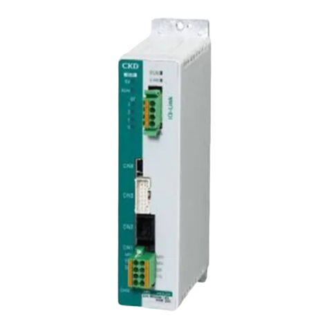
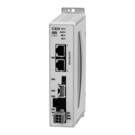
CKD ECG Series User manual

INSTRUCTION MANUAL
Instruction Manual
Controller for Electric actuators
ECG Series
EtherNet/IP Specifications
SM-A40833-A
•Be sure to read this instruction manual before using the product.
•Pay especially close attention to the safety-related information contained within.
•Keep this instruction manual in a safe place so that it is readily available when needed.

SM-A40833-APREFACE
i2021-01-13
PREFACE
Thank you for purchasing this CKD “ECG Series EtherNet/IP Specifications” controller for electric
actuators. In order for this product to be used to its fullest potential, this instruction manual describes
basic topics such as how to mount and use it. Read this manual thoroughly prior to use.
Keep this instruction manual in a safe place so that it is not lost.
The specifications and images in this instruction manual are subject to change without prior notice.

SM-A40833-ASAFETY INFORMATION
ii 2021-01-13
SAFETY INFORMATION
When designing and manufacturing equipment using this product, you are obligated to manufacture safe
equipment. Therefore, confirm that the safety of the equipment's mechanisms and the system that runs
the electrical controls can be ensured.
Ensure to observe organization’s standards, laws and regulations etc. for safety related to design and
management of the equipment.
It is important to select, use, handle and maintain CKD products appropriately to ensure their safe
usage.
Be sure to observe the warnings and precautions listed in this instruction manual to ensure equipment
safety.
This product is equipped with various safety measures. Even so, mishandling could cause an accident.
To prevent such an accident from occurring...
Make sure that you read this instruction manual thoroughly and understand its
content before use.
There are three levels of precautions to indicate the level and potential for danger or damage:
“DANGER,” “WARNING” and “CAUTION.”
DANGER
Mishandling could likely cause death or serious injury.
WARNING
Mishandling could cause death or serious injury.
CAUTION
Mishandling could cause injury or physical damage.
Note that some items indicated with “CAUTION” may lead to serious results depending on the
conditions.
All items contain important information and must be observed.
The following icon is used to indicate other general precautions and usage hints.
Indicates a general precaution or usage hint.

SM-A40833-ASAFETY INFORMATION
iii 2021-01-13
Product precautions
DANGER
Do not use this product for the following applications.
•Medical devices involved in maintaining or managing human life or health
•Mechanisms or machines meant to transfer or transport people
•Important security parts in machines
WARNING
The product must be handled by the person who has sufficient knowledge and experience.
This product was designed and manufactured as equipment and parts for general industrial
machinery.
Use this product in accordance with specifications.
It cannot be used outside of product-specific specifications. Never modify or additionally process
the product.
Since this product is intended for use in general industrial machinery equipment and parts, it is not
applicable to be used outdoors or in the following conditions and environments.
(It will be applicable if you consult with our company at the time of its adoption and understand the
specifications of our company's product. However, even in such a case, take safety measures to
avoid danger in case of failure.)
•Use in equipment and applications that come into direct contact with nuclear power, railways,
aviation, ships, vehicles, medical equipment, beverages and food.
•Use in applications requiring safety, such as recreational equipment, emergency shut off
circuits, press machines, brake circuits, and safety measures.
•Use in applications that are expected to have a significant impact on people and property and
require special safety.
Never handle the product or remove the equipment until safety is confirmed.
•Check and maintain the machinery and equipment only after confirming that all systems related
to the product are safe. Turn off the power supply of the equipment and the corresponding
equipment to prevent a short circuit.
•Even when the operation is stopped, there may be a high-temperature part or a charging part.
Handle the product and remove the equipment carefully.
Disposal precautions
CAUTION
When disposing of the product, follow laws and regulations related to processing and
cleaning waste. Request a specialized waste processing vendor to dispose of waste.

SM-A40833-ACONTENTS
iv 2021-01-13
CONTENTS
PREFACE........................................................................................................................... i
SAFETY INFORMATION .................................................................................................. ii
Product precautions.......................................................................................................iii
Disposal precautions .....................................................................................................iii
CONTENTS...................................................................................................................... iv
1. PRODUCT OVERVIEW ............................................................................................. 1
1.1 System Overview................................................................................................ 1
1.1.1 System structure.............................................................................................1
1.2 Instruction Manuals Related to This Product...................................................... 4
1.3 Names of Parts ................................................................................................... 5
1.3.1 LED.................................................................................................................5
1.4 Specifications...................................................................................................... 6
1.4.1 Communication specifications........................................................................ 6
1.5 Dimensions ......................................................................................................... 7
2. INSTALLATION ......................................................................................................... 8
2.1 Wiring method.....................................................................................................9
2.1.1 Connection and wiring to CN5 (interface connector)................................... 10
2.1.2 Other connections and wiring........................................................................11
3. USAGE..................................................................................................................... 12
3.1 Obtaining EDS files........................................................................................... 12
3.2 EtherNet/IP device setting ................................................................................ 13
3.3Communication format...................................................................................... 14
3.3.1 Data communication..................................................................................... 14
3.3.2 Send/receive data ........................................................................................ 14
3.3.3 Operation mode............................................................................................16
3.3.4 Implicit communication (input/output data) .................................................. 17
3.3.5 Cyclic data details for PIO mode.................................................................. 28
3.3.6 Data number................................................................................................. 38
3.4 Data access ......................................................................................................42
3.4.1 Implicit communication (input/output data) .................................................. 42
3.5 Operation time chart .........................................................................................43
3.5.1 Servo ON...................................................................................................... 43
3.5.2 From power-on to home position return....................................................... 44
3.5.3 Home position return operation....................................................................45
3.5.4 Positioning operation.................................................................................... 46
3.5.5 Monitor..........................................................................................................51
3.5.6 Data read...................................................................................................... 52
3.5.7 Data write .....................................................................................................53
4. WARRANTY PROVISIONS..................................................................................... 54
4.1 Warranty Conditions .........................................................................................54
4.2 Warranty Period ................................................................................................54

SM-A40833-A1. PRODUCT OVERVIEW
12021-01-13
1. PRODUCT OVERVIEW
1.1 System Overview
•EtherNet/IPTM is a registered trademark of ODVA.
•Windows is a registered trademark of Microsoft Corporation in the United States, Japan, and
other countries.
•Other company and product names in this document are company’s trademarks or registered
trademarks.
1.1.1 System structure
◼ECG-A Series

SM-A40833-A1. PRODUCT OVERVIEW
22021-01-13
Components in the system structure that are available from CKD are listed below.
Component
Product name/Model no.
This product
Controller
ECG-A Series
Accessories
Power connector
DFMC 1,5/ 3-STF-3,5 (PHOENIX CONTACT)
Sold separately
Actuator
EBS-G/EBR-G Series
Motor cable
EA-CBLM2-*
Encoder cable
EA-CBLE2--*
24 VDC power supply
EA-PWR-KHNA240F-24
Surge protector
AX-NSF-RAV-781BXZ-4
Noise filter
AX-NSF-NF2015A-OD
Provided for free
PC setting software
S-Tools
When using this product as a European standard-compliant product, refer to “6 Product Compliance” in
the instruction manual for the ECG series electric actuator controller (SM-A27751) and follow the
instructions.

SM-A40833-A1. PRODUCT OVERVIEW
32021-01-13
◼ECG-B Series

SM-A40833-A1. PRODUCT OVERVIEW
42021-01-13
Components in the system structure that are available from CKD are listed below.
Component
Product name/Model no.
This product
Controller
ECG-B Series
Accessories
Power connector
DFMC 1,5/ 3-STF-3,5 (PHOENIX CONTACT)
Sold separately
Actuator
FLSH-G/FLCR-G/FGRC-G Series
Motor and encoder relay cable
EA-CBLME2-*
24 VDC power supply
EA-PWR-KHNA240F-24
Surge protector
AX-NSF-RAV-781BXZ-4
Noise filter
AX-NSF-NF2015A-OD
Provided for free
PC setting software
S-Tools
When using this product as a European standard-compliant product, refer to “6 Product Compliance” in
the instruction manual for the ECG series electric actuator controller (SM-A27751) and follow the
instructions.
1.2 Instruction Manuals Related to This Product
This manual provides explanation of the EtherNet/IP specifications of the ECG series controller. For
mounting and setting parameter and point data, refer to the instruction manual for the ECG series
electric actuator controller (SM-A27751).
Item
Name
No.
Actuator
Electric actuator
EBS-G series (slider type)
EBR-G series (rod type with built-in guide)
SM-A28054
Electric actuator
FLSH-G Series
SM-A40839
Electric actuator
FLCR-G Series
SM-A40842
Electric actuator
FGRC-G Series
SM-A40845
Controller
Controller for Electric actuators
ECG series
SM-A27751
Setting software
PC Setting Software for Electric Actuators
S-Tools
SM-A11147

SM-A40833-A1. PRODUCT OVERVIEW
52021-01-13
1.3 Names of Parts
1.3.1 LED
Name
Color
Explanation
MS
Green, red
It indicates the network module status of this product.
NS
Green, red
It indicates the network status.
◼Communication status display
<MS>
LED Status
Operation
Off
Power OFF
Blinking green
Configuring communication
Lit green
Normal operation
Blinking red
A recoverable error has occurred.
Lit red
An irrecoverable error has occurred.
<NS>
LED Status
Operation
Off
Power is OFF or IP address not set
Blinking green
Connection not established
Lit green
Normal communication
Blinking red
Error (timeout)
Lit red
Error (duplicate IP address)

SM-A40833-A1. PRODUCT OVERVIEW
62021-01-13
1.4 Specifications
1.4.1 Communication specifications
Item
Details
Communication protocol
EtherNet/IP
Communication speed
Automatic setting
(100 Mbps/10 Mbps, full duplex/half duplex)
Allocated number of bytes
Input: 64 bytes / Output: 64 bytes
IP address
Setting by parameter (0.0.0.0 to 255.255.255.255)
Via DHCP server (arbitrary address)
RPI (packet interval)
4 ms to 10000 ms
Communication cable
Ethernet cable
(CAT5e or above twisted-pair cable (aluminum tape and braided
double-shield) recommended)
Vendor ID
201 (decimal)/0x00C9 (hexadecimal)
Product code
ECG-A: 117 (decimal) / 0x0075 (hexadecimal)
ECG-B: 118 (decimal) / 0x0076 (hexadecimal)
* When the power supply is turned OFF, the IP address obtained from the DHCP server will be deleted.

SM-A40833-A1. PRODUCT OVERVIEW
72021-01-13
1.5 Dimensions
◼Normal mounting
◼DIN rail mounting
Grounding terminal
(M3 5 pan head screw)

SM-A40833-A2. INSTALLATION
82021-01-13
2. INSTALLATION
DANGER
Do not use in locations with ignitable, flammable, or explosive substances or other such
dangerous substances.
There may be risk of ignition, combustion, or explosion.
Make sure that the product does not come in contact with water drops or oil drops.
Fire or damage may result.
When mounting the product, be sure to hold and fix it securely (including workpieces).
If the product is knocked over, falls, or experiences malfunction, it may lead to injury.
Use a DC stabilized power supply with surplus capacity (24 VDC ±10%) for the controller and
input/output circuit.
Connecting directly to an AC power supply may lead to fire, rupture, or damage.
WARNING
Design safety circuits or devices as the entire system including hardware in order to prevent
damage to the device or an accident resulting in injury or death in the event that a machine
stops due to system abnormality such as an emergency stop or a power failure.

SM-A40833-A2. INSTALLATION
92021-01-13
2.1 Wiring method
WARNING
Perform the wiring with the power supply turned OFF.
Touching the electrical wiring connections (bare charger) may cause electric shock.
Do not touch the charger with bare hands.
Doing so may cause electric shock.
Read and fully understand this instruction manual before performing the electrical wiring.
CAUTION
Check the working voltage and polarity before wiring and energizing.
Take countermeasures against lightning surges in the equipment side.
The product is not resistant to lightning surges.
For an AC voltage, use it in the installation category 2.
Use a dedicated communication cable conforming to the EtherNet/ IP specifications.
Secure a sufficient bending radius of the communication cable to avoid excessive bending.
Separate the communication cable from the power line or high voltage line.

SM-A40833-A2. INSTALLATION
10 2021-01-13
2.1.1 Connection and wiring to CN5 (interface connector)
This manual covers CN5 (interface connector) only.
EtherNet/IP is capable of the use of normal Ethernet cables and flexible wiring methods, but is limited by
the type of wiring, equipment, master, or hub to be used. Understand these specifications before
performing the wiring. For details, refer to the instruction manual of the master unit manufacturer or
ODVA.
A communication connector is not attached to this product. Purchase a communication connector that
meets the specifications separately.
Example of cable with connector
Manufacturer
Cable
Type
JMACS Japan Co., Ltd.
Industrial Ethernet cable
PNET/B-RJB-RJB/***□
***: cable length, □: M = meter, C = centimeter
Example of assembling type connector
Manufacturer
Connector
Type
3M Japan Limited
RJ45 modular plug for industrial use
3R104-1110-**0 AM
**: case color / cover color

SM-A40833-A2. INSTALLATION
11 2021-01-13
◼Connection method
<Network cable>
Follow the procedure below to connect the communication cable to CN5.
1 After confirming safety, stop communication and turn OFF the power of peripheral devices.
2 As shown below, route a communication cable conforming to the EtherNet/IP specifications.
Either a straight cable or a cross cable can be used.
Port
Pin
Signal
name
Function
IN/
OUT
1
TD+
Send data, plus
2
TD-
Send data, minus
3
RD+
Receive data, plus
4
Vacant
Vacant
5
Vacant
Vacant
6
RD-
Receive data, minus
7
Vacant
Vacant
8
Vacant
Vacant
2.1.2 Other connections and wiring
For other connection methods, refer to the instruction manual (SM-A27751) of the controller for the
electric actuator ECG series.

SM-A40833-A3. USAGE
12 2021-01-13
3. USAGE
•When using the ECG-B Series, ensure to set the actuator information using S-Tools. Refer to
the S-Tools instruction manual (SM-A11147) for setting the information.
•To use S-Tools with the settings of the ECG-A Series or ECG-B Series, the S-Tools version
must be as follows:
ECG-A Series, ECG-B Series: Version 1.04.00.00 or later
3.1 Obtaining EDS files
In order for the EtherNet/IP device to join the network, an EDS (Electronic Data Sheet) file describing the
communication specifications of the device must be installed in the configuration tool of the master unit.
Refer to the instruction manual of the master unit manufacturer for how to install the EDS file. Use the
latest EDS file to configure an appropriate network.
EDS files are available on the website of CKD (https://www.ckd.co.jp/).
<How to obtain>
1 Select “COMPONENT PRODUCTS” from the “PRODUCT INFORMATION” tab or the “PRODUCT
INFORMATION” page.
2 Select “Electric actuator” in the product lineup.
3 Select “Stepper motor drive.”
4 Access the detail page of “Controller Model No. ECG” from the product list.
5 Select “Software” and download “ECG Series EDS file(EtherNet/IP).zip.”

SM-A40833-A3. USAGE
13 2021-01-13
3.2 EtherNet/IP device setting
To connect this product as an EtherNet/IP device, it is necessary to set the product’s IP address and
other items in the PLC using a PLC development tool etc. Refer to the PLC manual for the PLC setting
method.
<Controller EtherNet/IP setting>
S-Tools can be used to change the IP address and other settings.
1 Select the “Settings” tab of S-Tools and click the [EtherNet/IP setting] button in the network
submenu.
2 Confirm that each set value has been set, and then select [Write].
Name
Description
Operation mode
Set the operation mode. Select “PIO,” “SDP,” or “FDP.” Note 1
IP address
It sets the IP address. Set the address in the range from 0.0.0.0 to 255.255.255.255.
Subnet mask
It sets the subnet mask. Set in the range from 0.0.0.0 to 255.255.255.255.
Default gateway
It sets the default gateway. Set in the range from 0.0.0.0 to 255.255.255.255.
DHCP
It is for selecting between “Disabled” and “Enabled.” When “Enabled” is selected, the IP address,
subnet mask, and default gateway are assigned automatically from the DHCP server.
Note 1: Refer to “3.3.3 Operation mode” for the operation mode.

SM-A40833-A3. USAGE
14 2021-01-13
3.3 Communication format
3.3.1 Data communication
Type of data communication
Description
Cyclic communication
This type of communication is used between the master and slave
on a set cycle.
Also called Implicit communication.
Message communication
This type of communication is used by a PLC or other host device
to access certain data on a slave through the master, when
needed.
Also called Explicit communication.
3.3.2 Send/receive data
The following data is transmitted and received between the PLC and the controller, and cyclic
communication is used for all data transmission and reception. Refer to “3.4 Data access” for the
communication method.
Name
Description
Accessible
Data
Transmitted/received
Data
Input/output signals
The actuator is operated in the same way as the controller
of the parallel I/O specifications.
-
3.3.4
3.3.5
Read data and write data
Set point data and user parameters, and check alarm
history.
3.3.6
3.3.4
Monitor
Position, speed, current, and alarm status are monitored.
-
3.3.4
◼Input/output signals
The items listed in the table below (signal name) are transmitted and received.
Classification
Item (signal name)
Data to be written to the controller by
the PLC
(Input data)
Point number selection bit n, point travel start, point number n travel start, solenoid valve
travel command n, solenoid valve travel command, servo ON, alarm reset, stop, pause,
INCH selection, JOG/INCH (+) travel start, JOG/INCH (-) travel start, direct value travel
selection, position, positioning width, speed, acceleration, deceleration, pressing rate,
pressing speed, pressing distance, mode, gain magnification
Data to be read from the controller by
the PLC
(Output data)
Point number confirmation bit n, point travel complete, point number n travel complete,
switch n, home position return complete, servo ON state, traveling, zone 1, zone 2, point
zone, alarm, warning, operation preparation complete, alarm confirmation bit n, direct
travel status
When the PIO mode is selected, the same items as the controller of the parallel I/O
specifications are sent and received.
When the simple direct value mode or full direct value mode is selected, and the direct value
travel is selected in the “direct value travel selection,” it is necessary to set the “position,”
“speed,” etc.

SM-A40833-A3. USAGE
15 2021-01-13
◼Write data and read data
Operate the following items.
Classification
Item
Data to be written to the controller by the PLC
(Input data)
Data number, data R/W selection, data request, write data
Data to be read from the controller by the PLC
(Output data)
Data write status, data complete, data response, read data, data (alarm)
<To read data>
Set the number of the data to be read in the “data number,” set the “data R/W selection” to 0 (read), then
turn the “data request” ON. The data of the number set in the “data number” will be output in the “read
data.”
<To write data>
After setting the number of the data to be written in the “data number” and setting the value to be written
in the “write data,” set the “data R/W selection” to 1 (write), then turn the “data request” ON.
*Check “data response” and “data completion” to see if the data was read or written correctly.
Setting point data and parameter and reading alarm history can also be performed using PC
setting software (S-Tools). For parameters that cannot be set from a PLC, use S-Tools.
◼Monitor
Operate the following items (signal name).
Classification
Item (signal name)
Data to be written to the controller by the PLC
(Input data)
Monitor No. n, monitor request
Data to be read from the controller by the PLC
(Output data)
Monitor response, monitor complete, monitor value n, position, speed, current,
alarm
When the data to be monitored is selected in “monitor No.,” and “monitor request” is turned ON, the
current value of the selected data is output in “monitor value.”
Other manuals for ECG Series
4
This manual suits for next models
1
Table of contents
Other CKD Controllers manuals

CKD
CKD KBX-30E-U Series User manual

CKD
CKD LN Series User manual

CKD
CKD ECG Series User manual

CKD
CKD EVD-1000 Series User manual

CKD
CKD KBX Series User manual

CKD
CKD PARECT MEVT Series User manual

CKD
CKD ECR Series User manual

CKD
CKD ER300 User manual

CKD
CKD EJSG Series User manual

CKD
CKD ECS Series User manual
Popular Controllers manuals by other brands

RESEARCH CONCEPTS
RESEARCH CONCEPTS RC4000 user manual

Emerson
Emerson Fisher easy-Drive 200R instruction manual

Musica
Musica MUSICAVC-70ZS installation instructions

Telecom Behnke
Telecom Behnke BEHNKE-STATION Technical manual

YASKAWA
YASKAWA Motoman DX200 instructions

Velleman
Velleman HQ-Power VDPDMXC146 manual