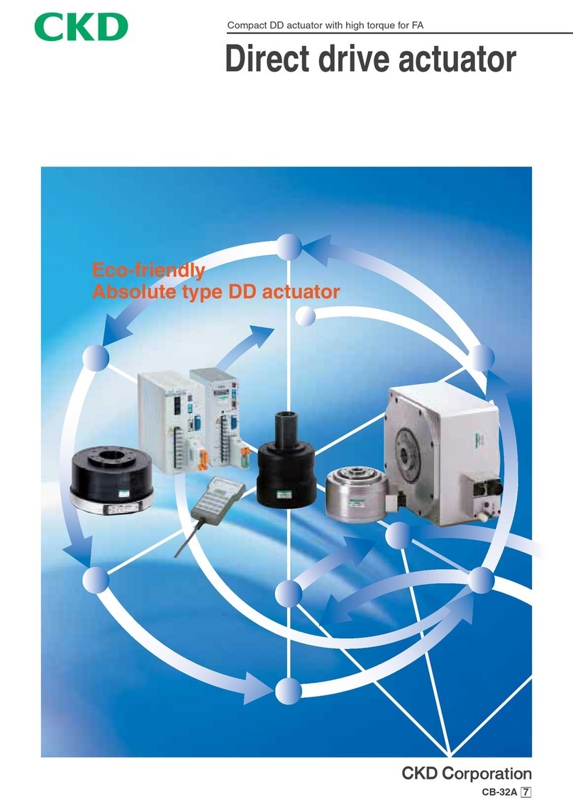
CKD ECG Series User manual

CKD Corporation
Controller for Electric Actuators
ECG Series
INSTRUCTION MANUAL
INSTRUCTION MANUAL
•Be sure to read this instruction manual before using the product.
•Pay especially close attention to the safety-related information contained within.
•Keep this instruction manual in a safe place so that it is readily available when needed.
SM-A27751-A/3
MSV-484083

SM-A27751-A/3 PREFACE
i2021-11-18
PREFACE
Thank you for purchasing this CKD “ECG” controller for electric actuators.
This Instruction Manual contains basic matters such as installation and usage instructions in order to
ensure optimal performance of the product. Please read this Instruction Manual thoroughly and use the
product properly.
Keep this Instruction Manual in a safe place and be careful not to lose it.
Product specifications and appearances presented in this Instruction Manual are subject to change
without notice.

SM-A27751-A/3 SAFETY INFORMATION
ii 2021-11-18
SAFETY INFORMATION
When designing and manufacturing equipment using this product, you are obligated to manufacture
safe equipment. Therefore, confirm that the safety of the equipment's mechanisms and the system that
runs the electrical controls can be ensured.
It is important to select, use, handle and maintain CKD products appropriately to ensure their safe
usage.
Be sure to observe the warnings and precautions listed in this instruction manual to ensure equipment
safety.
This product is equipped with various safety measures. Even so, mishandling could cause an accident.
To prevent such an accident from occurring...
Make sure that you read this instruction manual thoroughly and understand its
content before use.
There are three levels of precautions to indicate the level and potential for danger or damage:
“DANGER,” “WARNING,” and “CAUTION.”
DANGER
Mishandling could likely cause death or serious injury.
WARNING
Mishandling could cause death or serious injury.
CAUTION
Mishandling could cause injury or physical damage.
Note that some items indicated with “CAUTION” may lead to serious results depending on the
conditions.
All items contain important information and must be observed.
The following icon is used to indicate other general precautions and usage hints.
Indicates a general precaution or usage hint.

SM-A27751-A/3 SAFETY INFORMATION
iii 2021-11-18
Product precautions
DANGER
Do not use this product for the following applications.
•Medical devices involved in maintaining or managing human life or health
•Mechanisms or machines meant to transfer or transport people
•Important security parts in machines
WARNING
The product must be handled by the person who has sufficient knowledge and experience.
This product was designed and manufactured as equipment and parts for general industrial
machinery.
Use this product in accordance with specifications.
It cannot be used outside of product-specific specifications. Never modify or additionally process
the product.
Since this product is intended for use in general industrial machinery equipment and parts, it is not
applicable to be used outdoors or in the following conditions and environments.
(It will be applicable if you consult with our company at the time of its adoption and understand the
specifications of our company's product. However, even in such a case, take safety measures to
avoid danger in case of failure. )
•Use in equipment and applications that come into direct contact with nuclear power, railways,
aviation, ships, vehicles, medical equipment, beverages and food.
•Use in applications requiring safety, such as recreational equipment, emergency shut off
circuits, press machines, brake circuits, and safety measures.
•Use in applications that are expected to have a significant impact on people and property and
require special safety.
Never handle the product or remove the equipment until safety is confirmed.
•Check and maintain the machinery and equipment only after confirming that all systems
related to the product are safe. Turn off the power supply of the equipment and the
corresponding equipment to prevent a short circuit.
•Even when the operation is stopped, there may be a high-temperature part or a charging part.
Handle the product and remove the equipment carefully.
Regarding the safety related to the equipment design, observe the group standards, laws,
etc.
Disposal precautions
CAUTION
When disposing of the product, follow laws and regulations related to processing and
cleaning waste. Request a specialized waste processing vendor to dispose of waste.

SM-A27751-A/3 CONTENTS
iv 2021-11-18
CONTENTS
PREFACE........................................................................................................................... i
SAFETY INFORMATION .................................................................................................. ii
Product precautions.......................................................................................................iii
Disposal precautions .....................................................................................................iii
CONTENTS...................................................................................................................... iv
1. PRODUCT OVERVIEW ............................................................................................. 1
1.1 System Overview ................................................................................................ 1
System Structure and Workflow (ECG-A Series)......................................... 1
System Structure and Workflow (ECG-B Series)......................................... 3
1.2 Instruction Manuals Related to This Product...................................................... 6
1.3 Names of Parts ...................................................................................................7
1.4 Model Number Indication....................................................................................8
1.5 Specifications......................................................................................................9
Basic specifications ...................................................................................... 9
1.6 Dimensions ........................................................................................................11
ECG-A (Parallel I/O specifications) .............................................................11
ECG-B (Parallel I/O specifications)............................................................ 12
2. INSTALLATION ....................................................................................................... 13
2.1 Installation precautions ..................................................................................... 16
2.2 Unpacking .........................................................................................................16
2.3 Connection........................................................................................................17
Power supply wiring ................................................................................... 18
Actuator wiring............................................................................................ 21
I/O cable wiring........................................................................................... 26
S Tools setting software wiring................................................................... 33
3. USAGE..................................................................................................................... 34
3.1 Setting actuator information..............................................................................35
3.2 PARAMETERS DATA CONFIGURATION ........................................................ 36
Parameters List .......................................................................................... 36
Soft limit...................................................................................................... 39
Zone output ................................................................................................ 40
Adjusting the gains ..................................................................................... 42
3.3 POINT DATA CONFIGURATION ...................................................................... 47
Positioning point ......................................................................................... 47
Point data list.............................................................................................. 48
Selecting the position specification method............................................... 49
Selecting the operation method ................................................................. 50
Setting the position..................................................................................... 51
Setting the positioning width ...................................................................... 52
Setting the speed ....................................................................................... 53
Setting the acceleration.............................................................................. 56
Setting the deceleration.............................................................................. 56
Selecting the acceleration/deceleration method ........................................ 57
Selecting the stop method.......................................................................... 57
Selecting the rotation direction................................................................... 58
Setting the gain magnification.................................................................... 59
Setting the point zone................................................................................. 59
Setting the pressing rate ............................................................................ 60
Setting the pressing speed......................................................................... 61
Setting the pressing distance ..................................................................... 61


SM-A27751-A/3 CONTENTS
v2021-11-18
3.4 OPERATION ..................................................................................................... 62
Emergency stop and release ..................................................................... 62
Force brake release ................................................................................... 63
Servo ON/OFF............................................................................................ 64
From power-on to home position return..................................................... 65
Home position return operation.................................................................. 66
Positioning operation.................................................................................. 76
Other output signals ................................................................................... 87
Pressing operation ..................................................................................... 88
Operation when a new operation signal is input during operation............. 90
Stop signal input......................................................................................... 91
Holding operation after travel complete ..................................................... 92
4. Maintenance and inspection................................................................................. 93
5. Troubleshooting ..................................................................................................... 94
5.1 Alarm Indications and Countermeasures ......................................................... 94
5.2 What to Check when Trouble Occurs...............................................................97
5.3 Problems, Causes, and Solutions ....................................................................98
6. PRODUCT COMPLIANCE ....................................................................................100
6.1 EU Directives/European standards ................................................................100
6.2 Precautions when used in Europe (EU) ......................................................... 100
Suitable actuators.....................................................................................100
Working environment ...............................................................................100
System structures.....................................................................................101
7. WARRANTY PROVISIONS................................................................................... 104
7.1 Warranty Conditions .......................................................................................104
7.2 Warranty Period ..............................................................................................104

SM-A27751-A/3 1. PRODUCT OVERVIEW
12021-11-18
1. PRODUCT OVERVIEW
1.1 System Overview
Check “1.1.1 System Structure and Workflow (ECG-A Series)” if you have purchased the ECG-A Series
and “1.1.2 System Structure and Workflow (ECG-B Series)” if you have purchased the ECG-B Series.
System Structure and Workflow (ECG-A Series)
◼System structure

SM-A27751-A/3 1. PRODUCT OVERVIEW
22021-11-18
System components that can be purchased from CKD are listed below.
Component
Product name/Model no.
This product
Controller
ECG-A Series
Accessories
Power supply connector
DFMC 1,5/ 3-STF-3,5 (PHOENIX CONTACT)
I/O cable
EA-CBLNP2- *
Sold separately
Actuator
EBS-G/EBR-G Series
Motor cable
EA-CBLM2- * Note1
Encoder cable
EA-CBLE2- * Note1
24 VDC power supply
EA-PWR-KHNA240F-24
Noise filter
AX-NSF-NF2015A-OD
Provided for free
PC setting software
S-Tools
Note 1: For the P4 Series, the motor cable model No. is "EA-CBLM3-*" and the encoder cable model No. is "EA-CBLE3-*".
To use this product as a product conforming to the European standards, refer to “6 PRODUCT
COMPLIANCE” and follow the instructions.
◼Workflow
Follow the steps below to wire and set the controller so that it can be operated from the PLC.
1 Unpacking
Take the product out of the box. Refer to “2.2 Unpacking” for more information.
2 Wiring the power supply
Wire the power supply for the controller. Refer to “2.3.1 Power supply wiring” for more information.
3 Wiring the actuator
Connect the controller and the actuator. Refer to “2.3.2 Actuator wiring” for more information.
4 Wiring I/O cable
Wire the controller and the PLC. Refer to “2.3.3 I/O cable wiring” for more information.
5 Wiring S-Tools
Connect the controller and the PC. Refer to “2.3.4 S Tools setting software wiring” for more
information.
6 Setting parameters and point data
Determine the controller setting. Refer to “3.2 PARAMETERS DATA CONFIGURATION” and “3.3
POINT DATA CONFIGURATION” for more information.
7 Operation
Operate the actuator using the PLC. Refer to “3.4 OPERATION” for more information.
•The work in steps 3 to 6 are not placed in order: adjust the order according to your
requirement.
•When using a parallel I/O controller, use S-Tools for setting parameters and point data,
because they cannot be set from a PLC.

SM-A27751-A/3 1. PRODUCT OVERVIEW
32021-11-18
System Structure and Workflow (ECG-B Series)
◼System structure

SM-A27751-A/3 1. PRODUCT OVERVIEW
42021-11-18
System components that can be purchased from CKD are listed below.
Component
Product name/Model no.
This product
Controller
ECG-B Series
Accessories
Power supply connector
DFMC 1,5/ 3-STF-3,5 (PHOENIX CONTACT)
I/O cable
EA-CBLNP2-*
Sold separately
Actuator
FLSH-G/FLCR-G/FGRC-G Series
Motor and encoder relay cable
EA-CBLME2-*
24 VDC power supply
EA-PWR-KHNA240F-24
Surge protector
AX-NSF-RAV-781BXZ-4
Noise filter
AX-NSF-NF2015A-OD
Provided for free
PC setting software
S-Tools
To use this product as a product conforming to the European standards, refer to “6 PRODUCT
COMPLIANCE” and follow the instructions.

SM-A27751-A/3 1. PRODUCT OVERVIEW
52021-11-18
◼Workflow
CAUTION
Set actuator information corresponding to the actuator connected to the controller.
Setting incorrect information may cause the actuator to make unexpected actions, resulting in
injury to people nearby or damage to the actuator.
Follow the steps below to wire and set the controller so that it can be operated from the PLC.
1 Unpacking
Take the product out of the box. Refer to “2.2 Unpacking” for more information.
2 Wiring the power supply
Wire the power supply for the controller. Refer to “2.3.1 Power supply wiring” for more information.
3 Wiring the actuator
Connect the controller and the actuator. Refer to “2.3.2 Actuator wiring” for more information.
4 Wiring I/O cable
Wire the controller and the PLC. Refer to “2.3.3 I/O cable wiring“ for more information.
5 Wiring S-Tools
Connect the controller and the PC. Refer to “2.3.4 S Tools setting software wiring“ for more
information.
6 Setting actuator information
Set the information of the actuator connected to the controller. Refer to “3.1 Setting actuator
information” for more information.
7 Setting parameters and point data
Determine the controller setting. Refer to “3.2 PARAMETERS DATA CONFIGURATION” and “3.3
POINT DATA CONFIGURATION” for more information.
8 Operation
Operate the actuator using the PLC. Refer to “3.4 OPERATION” for more information.
•The work in steps 3 to 7 are not placed in order: adjust the order according to your
requirement. However, “set the actuator information” before “setting the parameter and point
data.”
•Use S-Tools, setting software, for setting the actuator information.
•When using a parallel I/O controller, use S-Tools for setting parameters and point data,
because they cannot be set from a PLC.

SM-A27751-A/3 1. PRODUCT OVERVIEW
62021-11-18
1.2 Instruction Manuals Related to This Product
The table below lists instruction manuals of actuators, interfaces and setting software related to this
product.
Items
Part name
No.
Actuator
Electric Actuator
EBS-G series (slider type)
EBR-G series (rod type with built in guide)
SM-A28054
Electric Actuator
FLSH-G Series
SM-A40839
Electric Actuator
FLCR-G Series
SM-A40842
Electric Actuator
FGRC-G Series
SM-A40845
Interface specifications Note 1
Controller for Electric Actuators
ECG series IO-Link specifications
SM-A40831
Controller for Electric Actuators
ECG series CC Link specifications
SM-A27752
Controller for Electric Actuators
ECG series EtherCAT specifications
SM-A40832
Controller for Electric Actuators
ECG series EtherNet/IP specifications
SM-A40833
Setting software
PC Setting Software for Electric Actuators
S-Tools
SM-A11147
Note 1: When using a controller whose interface specifications are not parallel I/O specifications, refer to the instruction manuals shown
in the table above.

SM-A27751-A/3 1. PRODUCT OVERVIEW
72021-11-18
1.3 Names of Parts
Code
Name
Description
SV
Servo lamp
[If there is no alarm]Indicates whether servo is ON or OFF
Servo ON: Steady green
Servo OFF: Blinking green (lit once per second)
[If there is alarm] Indicates the most significant digit n of the alarm code.
Occurrence of alarm 0xn***: Blinking green (repeats the following: off for two seconds, then
lit once per second n times)
ALM
Alarm lamp
Indicates an alarm/warning has occurred
Occurrence of alarm which cannot be released: Steady red
Occurrence of alarm which can be released: Blinking red (lit once per second)
Occurrence of warning: Blinking red (lit once every two seconds)
CN1
Power supply connector
Connector used to connect the controller to the power
Refer to “2.3.1 Power supply wiring” for information on wiring method.
CN2
Motor connector
Connector used to connect the motor cable
Refer to “2.3.2 Actuator wiring” for connection cables.
CN3
Encoder connector
Connector used to connect the encoder cable
Refer to “2.3.2 Actuator wiring” for connection cables.
CN4
USB connector
Connector used to connect the setting tool (PC setting software)
Connection cable: Commercially available USB cable (mini-B type)
CN5
Interface connector
Connector used to connect the upper device
Refer to “2.3.3 I/O cable wiring” for wiring information.
Connection cable model No.: EA-CBLNP2-**
A or B
Controller identification
Symbols and usable actuators vary depending on the controller.
If the symbol is A, the controller is the ECG-A Series and the corresponding actuators are
the EBS-G and EBR-G Series. If the symbol is B, the controller is ECG-B Series and the
corresponding actuators are FLSH-G Series, FLCR-G series and FGRC-G series.
*For the supporting of the alarm code and alarm description, refer to “ 5.1 Alarm Indications and Countermeasures“.
ALM: Alarm lamp
SV: Servo lamp
CN4: USB connector
CN3: Encoder connector
CN2: Motor connector
CN1: Power supply connector
CN5: Interface connector
A or B: Controller identification

SM-A27751-A/3 1. PRODUCT OVERVIEW
82021-11-18
1.4 Model Number Indication
*C: The I/O cable length can only be selected when the interface specification is I/O specification. In a
case other than the I/O specification, 00 only.
◼ECG-A Series
◼ECG-B Series

SM-A27751-A/3 1. PRODUCT OVERVIEW
92021-11-18
1.5 Specifications
Basic specifications
◼ECG-A Series
Items
Descriptions
Applicable actuators
EBS-G/EBR-G
Setting tool
Setting software (S-Tools)
Operation mode (PIO)
64-point mode, simple 7-point mode, solenoid valve mode double 2 position type,
solenoid valve mode double 3 position type, solenoid valve mode single type
Number of inputs
13 points
Number of outputs
13 points
Power supply voltage
24 VDC ±10%
Indicator lamps
SV: Servo lamp, ALM: Alarm lamp
Brake release input
24 VDC ±10%
Emergency stop release input
24 VDC ±10%
Insulation resistance
10 M Ω or more with 500 VDC
Withstand voltage
500 VAC for 1 min.
Specified ambient
temperature
0 to 40°C (no freezing)
Specified ambient humidity
35 to 80% RH (no condensation)
Storage ambient temperature
-10 to 50°C (no freezing)
Storage ambient humidity
35 to 80% RH (no condensation)
Specified atmosphere
No corrosive gas, explosive gas, or dust
Degree of protection
IP20
Weight
Parallel I/O
specifications
Standard mounting: approx. 180 g
DIN rail mounting: approx. 210 g
Others
Standard mounting: approx. 310 g
DIN rail mounting: approx. 340 g

SM-A27751-A/3 1. PRODUCT OVERVIEW
10 2021-11-18
◼ECG-B Series
Items
Descriptions
Applicable actuators
FLSH-G/FLCR-G/FGRC-G
Setting tool
Setting software (S-Tools)
Operation mode (PIO)
64-point mode, simple 7-point mode, solenoid valve mode double 2 position type,
solenoid valve mode double 3 position type, solenoid valve mode single type
Number of inputs
13 points
Number of outputs
13 points
Power supply voltage
24 VDC ±10%
Indicator lamps
SV: Servo lamp, ALM: Alarm lamp
Brake release input
24 VDC ±10%
Emergency stop release input
24 VDC ±10%
Insulation resistance
10 M Ω or more with 500 VDC
Withstand voltage
500 VAC for 1 min.
Specified ambient
temperature
0 to 40°C (no freezing)
Specified ambient humidity
35 to 80% RH (no condensation)
Storage ambient temperature
-10 to 50°C (no freezing)
Storage ambient humidity
35 to 80% RH (no condensation)
Specified atmosphere
No corrosive gas, explosive gas, or dust
Degree of protection
IP20
Weight
Standard mounting: approx. 310 g
DIN rail mounting: approx. 340 g

SM-A27751-A/3 1. PRODUCT OVERVIEW
11 2021-11-18
1.6 Dimensions
For the external dimensions of controllers with other specifications than parallel I/O specifications, refer
to the instruction manual for each interface specification.
ECG-A (Parallel I/O specifications)
◼Normal mount
◼DIN rail mount
Grounding terminal
(M3 5 pan head screw)

SM-A27751-A/3 1. PRODUCT OVERVIEW
12 2021-11-18
ECG-B (Parallel I/O specifications)
◼Normal mount
◼DIN rail mount
Grounding terminal
(M3 5 pan head screw)

SM-A27751-A/3 2. INSTALLATION
13 2021-11-18
2. INSTALLATION
DANGER
Do not use the product in a place where dangerous substances such as ignitable,
inflammable, or explosive materials are present.
Ignition, inflammation, or explosion may occur.
Prevent water and oil from splashing onto the product.
A fire, electric leakage, or failure may occur. Even oil drops and oil mists are prohibited.
Make sure to hold and secure the product (including the workpiece) while installing the
product.
An injury may occur if the product falls down, falls off, or operates abnormally.
Use a DC stabilized power supply (24 VDC) with sufficient capacity as a power supply for
the controller and the input/output circuit.
If the product is directly connected to an AC power supply, a fire, burst or damage may occur.
When connecting a personal computer, prevent frame ground (FG) of the computer.
If a plus terminal of the product is grounded, connecting the product to a PC and peripheral
equipment with a USB cable may cause short-circuit in the DC power supply.
Install overcurrent protective equipment (such as a breaker for wiring and a circuit
protector) on the primary side of the power supply when wiring in accordance with "JIS B
9960-1: 2019(IEC 60204-1:2016) Safety of machinery - Electrical equipment of machines -
Part 1: General requirements".

SM-A27751-A/3 2. INSTALLATION
14 2021-11-18
WARNING
Do not install the product on combustibles.
Fire may result if the product is installed directly on or near combustibles.
Design a safety circuit or device to prevent damage to the equipment or an accident
resulting in injury or death when the machine stops due to an emergency stop, power
failure, or other system abnormalities.
Install the product in a dry indoor place.
Short circuit or fire can occur if the product is put in a wet or humid place (a place with a humidity
of 80% or higher with dew condensation).
The product must be subjected to class D grounding work (ground resistance of 100 Ω or
less).
Short circuit may cause electric shock or malfunction.
Perform the wiring of the product securely so as not to cause miswiring or loosening of
connectors, as confirmed in this instruction manual. Also, check the insulation of the wiring.
Ensure that there is no contact with other circuits, ground fault, or insulation failure between
terminals. Overcurrent may flow into the product and cause damage. This may cause malfunction
and fire.
Insulate the wiring that is not used.
Failure to do so may result in malfunction, failure, or electric shock.
Do not damage the cable, apply unreasonable stress, put heavy objects on it, or pinch it.
Doing so may cause poor electrical continuity or electrical shock.
Do not connect the communication connector of the product to other devices.
A malfunction or damage may occur.
Use an actuator with a brake when the actuator is not mounted horizontally.
If the product is not equipped with a brake, it may cause injury or damage to the workpiece due to
fall of the movable part at the servo OFF (including emergency stop and alarm) or the power OFF.
Do not hold the movable part or cable part of the product during transportation or
installation.
Doing so may cause injury or wire disconnection.
Other manuals for ECG Series
4
This manual suits for next models
2
Table of contents
Other CKD Controllers manuals

CKD
CKD AX Series User manual

CKD
CKD KBZ Series User manual

CKD
CKD SELEX F.R.L. Series User manual

CKD
CKD FGRC Series User manual

CKD
CKD ECG Series User manual

CKD
CKD AX1R Series User manual

CKD
CKD SM-A10616-A User manual

CKD
CKD KBX Series User manual

CKD
CKD KBX-T5 User manual

CKD
CKD AX1000T Series User manual
Popular Controllers manuals by other brands

Technische Alternative
Technische Alternative UVR610 General programming information, User manual

Moeller
Moeller easyControl EC4-200 installation instructions

Pichler
Pichler XQ+ 15 user manual

Mi-Light
Mi-Light MiBOXER FUT041 manual

PCS Electronics
PCS Electronics PEBBLE Quick setup guide

Vacon
Vacon 100 INDUSTRIAL Technical guide