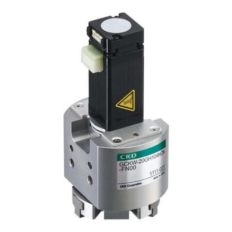
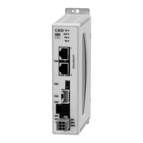
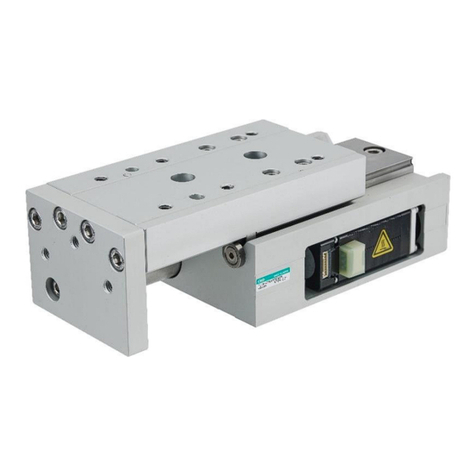
CKD ABSODEX MINI AX6000M Series User manual

“Small and easy to use”
Desktop DD actuator birth
New P
roduct
New Product
ABSODEX MINI type
AX6000M Series
CC-1148A

It is not just small but easy to use!
Space-saving
Flexible
High reliability & maintenance free
In addition to industry min. external dimensions, for the concentric shape
(the fixed axis and the rotation axis is the same), compact equipment design
that saves a waste of space is possible.
Operation can be realized as imagined because it has abundant program creation
functions. Furthermore, it corresponds to simple operation settings such as
automatic creation of point specified programs.
ABSODEX
Electric actuator with
speed reduction mechanism
Complex operation settings such as a combination of operations are also surprisingly simple!
Index operation Oscillator Continuous Rotation
Because of the direct-drive system (gearless), there is no need to worry about gear
damage or accuracy changes through wear of the gear unit.
Worry about damage
and wear of the gear
Gearless configuration
Industry min.
* Our company's research in August 2013
80mm
120mm (CD Size) * Full size
Please try to
place the work
piece in practice.
Smartphone size
47mm

Equipment automation can be easily achieved.
Because of the DD actuator, from design to operation it is simple and effortless.
Design
Purchasing
Assembly
Driving
Maintenance
Please try it!!
Inventory can be reduced with possible reuse.
The pilot and positioning pin hole are standard equipment.
Assembly and adjustment effort can be reduced.
For the Set Model No. (Motor+Driver+Cable) ordering is simple.
Drive system parts (pulley, belt, gear) purchasing is unnecessary.
Through the check sheet (Attached) models can be selected.
The number of design processes can be reduced because
there is a simple structure with no bulge in the gear portion.
Further added improvements have made operation setting
in personal computer tools easy.
It can move smoothly with positioning in the optimal
cam curve.
Use cases
With the feeling of “Just put it on the table” you can design equipment.
It is equipped with a wealth of features that are appropriate for an index table
such as split position output (stop position output) and I/O signal output during
indexing, and it is also possible to reduce the external sensor.
Point
of success
Semi-automation of
manual operation
θ-axis unit when making
a module of equipment
<Purpose>
• Productivity improvement
• Work stabilization
<Purpose>
• Reduction of equipment design time
• Equipment reuse
Addition as a sub-assembly
process to existing equipment
(Replacement of existing equipment components)
<Purpose>
• Tact improvement of the entire equipment
• Miniaturization of existing equipment
AX4000T
Series
AX2000T
Series
AX1000T
Series
Existing ABSODEX and program parameters (except for some) can be shared.

Intro 5
System Conguration
Basic setting items
1. Input the program from a personal computer.
2. Set required parameters the same way.
3. Set the appropriate gain.
Basic drive methods
1. A program to be executed is selected at the PLC.
2. Start signal is input at the PLC.
3. After operation, the driver outputs a positioning
completion signal.
Personal computer *
GND
Electromagnetic
contactor
(any)
*
Resolver cable
Motor cable
GND
PLC *
Power
*
GND
Driver
DC24V power supply
(sold separately)
Noise filter
(sold separately)
RS-232C
Communication cable
(sold separately)
I/O connector
(Driver accessory)
ABSODEX
Actuator body
Configuration (set model no. selection)
Name Quantity
Actuator body 1
Driver (with controller) 1
Motor cable and resolver cable 1 each
I/O connector, power supply connector, power supply connector open tool
* The motor cable connector is attached to the motor cable.
Programming tool
• Startingadjustmentsupporttool"AXTools"isavailable.
(Windows version, free)
ABSODEXprogramsarecreated,parametersset,and
operation commands, etc., issued from the personal
computer.
Created programs can be saved.
Communication cable RS-232C (D-sub 9-pin (2 m)
model:AX-RS232C-9P)isrequired.
Note)
The communication cable is designed specifically
forABSODEX.Youcannotuseacableavailable
on the market. If you do, the driver or PC may
be damaged.
Note)
The RS-232C communication cable is assumed
tobeusedonlywhenadjustingtheconnection.
Remove the cable from CN1 during normal operation.
Note)
Do not allow the PC to enter the standby mode
when a USB-serial adapter cable is connected.
If it does, communication errors may result when
the PC returns from the standby mode.
Note)
Downloadthelatestversionoftheadjustment
supporttool"AXTools"fromourwebsite.
* Prepared by the user.

Intro 6
ABSODEX MINI type AX6000MSeriesVariation
Torque (N•m)
Index accuracy
(sec.)
Repeatability
(sec.)
Page
1.2 3
±90 ±10 1
Drivers can be commonly
used.
The controller function
enables the actuator's
rotation angle, movement
time and timer, etc., to be
set as desired with an
NC program.
M code output, encoder
output, etc. can be used to
connect to an external PLC,
motion controller, etc.
5
Related parts model number table ............. Page 8
Selection guide........................................... Page 9
Safety precautions ...............................Page 11
ACTUATORCompatible driver

1
ACTUATOR SPECIFICATIONS
ABSODEX
AX6000M Series
Compatible function with free driver, actuator, and cable combinations
Diameter80mmminimumsize
Max. torque: 1.2Nm, 3Nm
Compatible driver: MU Type Driver
Items AX6001M AX6003M
Max. output torque N・m1.2 3.0
Continuous output torque N・m0.4 1.0
Max. rotation speed rpm 240 (Note 1)
Allowable axial load N600
Allowable moment load N・m 5
Output shaft moment of inertia kg・m20.00034 0.00059
Allowable load inertia moment kg・m20.034 0.059
Index accuracy (Note 2) sec. ±90
Repeatability (Note 2) sec. ±10
Output shaft friction torque N・m0.13 0.22
Resolver resolution P/rev 540672
Motor insulation class A
Motor withstand voltage AC550V 1 minute
Motor insulation resistance 10MΩandover DC500V
Ambient temperature 0~40°C
Ambient humidity 20~85%RHNofreezing
Storage temperature -10~65°C
Storage ambient humidity 20~90%RHNofreezing
Atmosphere Free of corrosive and explosive gases and dust
Weight kg 1.2 1.8
Run out of output shaft (Note 2) mm 0.03
Surface run out of output shaft (Note 2) mm 0.05
Degree of protection IP20
Note1:Use80rpmorlessduringcontinuousrotaryoperation.
Note 2:
Fordetailsonindexprecision,repeatability,runoutofoutputshaft,andsurfacerunoutofoutputshaft,referto"Terminology"onpage10.
Speed and maximum torque characteristics
F
F
L
(Note) Moment load
M(N•m)=F(N)×L(m)
M : Moment load
F : Load
L : Distance from output shaft center
M(N•m)=F(N)×(L+0.02)(m)
M : Moment load
F : Load
L : Distance from output shaft flange
(Fig.a) (Fig.b)
L
Read Precautions on page 11 to 15 before use.
AX6001M AX6003M
[rpm]
300
200
100
50
250
150
0
0 0.5 1 1.5 [N•m]
* Graph shows the typical value during 24 VDC (Ambient temperature: 25 °C)
Continuous
movement
range
Intermittent
movement range
[rpm]
300
200
100
50
250
150
0
0 21 3 4 [N•m]
Continuous
movement
range
Intermittent
movement range
* Graph shows the typical value during 24 VDC (Ambient temperature: 25 °C)

2
How to order
AX6000M Series
()
How to order
CMounting
base
EInterface
specifications
BDriver type
Model no.
ASize
(Max. torque)
DCable length
Set model no. (actuator, driver, and cable)
Actuator model no. Driver model no. Cable model no.
ASize CMounting base EInterface
specifications
DCable length
Note:"04"ifthecable
lengthis4m
•Motorcable
•Resolvercable
Model Model no. of options
AX6 001 MU BS U0D04
Symbol
Descriptions
A Size (Max. torque)
001 1.2N•m
003 3.0N•m
B Driver type
MU With MU type driver
E Interface specifications
U0 Parallel I/O (NPN specifications)
C Mounting base
Blank
Standard (without mounting base)
BS Electroless nickel plating
Surface treatment installation
DCable length
D02
Standard 2m
D04
Standard4m
D06
Standard 6m
D08
Standard 8m
D10
Standard10m
DM02
Movable 2m
DM04
Movable4m
DM06
Movable 6m
DM08
Movable 8m
DM10
Movable10m
AX6 M001 BS AX9000MU U0 AX-CBLM8 D04
AX-CBLR8 D04
Model no.

3
AX6000M Series
AX6001M
Dimensions
Note 1: The actuator's origin may differ from that in the dimensional drawing.
The origin offset feature enables you to set the origin to any position you choose.
Note 2: In the cable lead-out portion there is an exposed portion of the shield braided wire.
4×M4Depth6.5(straight)
For mounting rotary table
Rotary Section
(Including hollow section)
Fixed Section
Outletcablelength300mm
(Note) It is not a movable cable.
4×M4Depth8(straight)
Platform for mounting
(Note) Fix the end of the cable sheath
when bending repeatedly.
(Note) Min. bending range
outletcableis50mm. 80
80
4×ø4.8
Mounting base (Option)
4×C4
4.5Depth4
+0.2
0
ø80 0
-0.2
ø18h8
ø60h8
ø13
ø80
4×ø3.4
Connectorcasexing
4
+0.05
0
(ø18reference)
37
P.C.D.74
(R)
45°
65
65
47
40 (3)
4
17
(95.4)
(3.5)
(3.5) (3.5)
(16.5)
45°
(16.5)
18
34.4
41.4
(3.5)
80
87
(10)
7
P.C.D.70
(Note 2)
Not available if the
optional mounting
base is installed.
4
+0.05
0
4.5Depth5
+0.2
0
(ø60reference)
35
(R)

4
Dimensions
AX6000M Series
Dimensions
AX6003M
Note 1: The actuator's origin may differ from that in the dimensional drawing.
The origin offset feature enables you to set the origin to any position you choose.
Note 2: In the cable lead-out portion there is an exposed portion of the shield braided wire.
(Note) Fix the end of the cable sheath
when bending repeatedly. Outletcablelength300mm
(Note) It is not a movable cable.
4×M4Depth8(straight)
Platform for mounting
Rotary Section
(Including hollow section)
4×M4Depth6.5(straight)
For mounting rotary table
(Note) Min. bending range outlet
cableis50mm. 80
80
4×ø4.8
Mounting base (Option)
4×C4
4.5Depth4
+0.2
0
ø80 0
-0.2
ø18h8
ø60h8 Fixed Section
ø13
ø80
4×ø3.4
4
+0.05
0
(ø18reference)
37
P.C.D.74
(R)
45°
65
65
67
60 (3)
4
17
(95.4)
(3.5)
(3.5) (3.5)
(16.5)
45°
(16.5)
18
34.4
41.4
(3.5)
80
87
(10)
7
P.C.D.70
Not available if the
optional mounting
base is installed.
4
+0.05
0
4.5Depth5
+0.2
0
(ø60reference)
35
(R)
Connectorcasexing
(Note 2)

5
ABSODEX
MU Type Driver
Common specifications Performance Specifications
Items Descriptions
Control shafts 1shaft,540672pulses/1rotation
Angle setting unit °(degrees),pulses,indexnumbers
Min. angle setting unit 0.001°,1pulse
Speed setting unit sec. rpm
Speed setting range 0.01~100s/0.01~240rpm
Equal divisions 1~255
Max. command value 7-digitnumberinput±9999999
Timer 0.01sto99.99s
Program language NC language
Programming method
Data can be set with an interactive
terminal or personal computer, etc.,
using the RS-232C port.
Operation Mode Auto,job,singleblock,servoOFF,
pulse string input
Acceleration curve
<5 types>
Modified sine (MS),
modified constant velocity (MC,MC2),
modifiedtrapezoidal(MT),
and trapecloid (TR)
Status display
RUN: Normal operating state
ALM2: Alarm 2 state
ALM1: Alarm 1 state
SERVO:Servostate
CHARGE: Charge state
Communication
interface RS-232C compliant
I/O signals Refer to the relevant interface
specifications page.
Programsize Approx.6000characters(256lines)
Electronic thermal Actuator overheat protection
Power supply
Actuator Model Driver Model Rated input
current Max. input
current
AX6001M,AX6003M AX9000MU 3.3A 10A
Interface specifications: Parallel I/O (NPN specifications)
Main features
Miniature/light weight (resin body)
Wiring is easy for the connector connection
How to order
Items Descriptions
Product name MU Type Driver
AX9000MU
Power
voltage
Main
power
supply
DC24V±10%
Control
power
supply
DC24V±10%
Structure Integrated driver and controller
Ambient
temperature 0~50°C
Ambient
humidity 20~90%RH(nofreezing)
Operating
ambient
temperature
−10~65°C
Operating
ambient
humidity
20~90%RH(nofreezing)
Atmosphere No corrosive gases or powder dust.
Noise resistance
1000V(P-P),pulsewidth1μs,risingedge1ns,
impulse noise test, induction noise
(capacitive coupling)
Vibration
resistance 4.9m/s2
Weight Approx.0.5kg
Degree of
protection IP2X
AX9000MU U0

6
MU type driver
CN3 I/O circuit specifications
I/O circuit specifications
Descriptions
1 circuit
current
(mA)
Max.
points
(circuit)
Max.
current
(mA)
Max. current
consumption
(mA)
Input circuit 414 56
746Output circuit 30 18 540
Brake output (BK+,BK-) 75 2150
* The maximum number of simultaneous output points for the output circuits
is14outof18.
CN3 output signal
Pin no. Signal Logic
33 Mcodeoutput(bit0) Positive
34 M code output (bit 1) Positive
35 M code output (bit 2) Positive
36 M code output (bit 3) Positive
37 Mcodeoutput(bit4) Positive
38 M code output (bit 5) Positive
39 M code output (bit 6) Positive
40 Mcodeoutput(bit7) Positive
41 In-position output Positive
42 Positioning completion output Positive
43 Start input waiting output Positive
44 Alarm output 1 Negative
45 Alarm output 2 Negative
46 Intermediate index output 1/origin output Positive
47 Intermediate index output 2/servo state output Positive
48 Ready output Positive
49 Segment position strobe output Positive
50 M code strobe output Positive
CN3 Input signal
Pin no. Signal Logic Decision
1~2 Externalpowersupplyinput+24V±10%
3~4 External power supply input GND
5Programnumberselectioninput(bit0) Positive Level
6Program number selection input (bit 1) Positive Level
7Program number selection input (bit 2) Positive Level
8Program number selection input (bit 3) Positive Level
9Program number selection input 2nd digit/
programnumberselectioninput(bit4) Positive Edge
Level
10 Program number selection input 1st digit/
program number selection input (bit 5) Positive Edge
Level
11 Reset input Positive Edge
12 Home Positioning Instruction Input Positive Edge
13 Start input Positive Edge
14
Servo ON input/program stop input
Positive Level
Edge
15 Continuous rotation stop input Positive Edge
16
Answer input/position deviation counter reset
Positive Edge
17 Emergency Stop Input Negative Level
18 Brake Release Input Positive Level
CN3 pulse string input signal
Pin no. Signal
19 PULSE/UP/A phase
20 -PULSE/-UP/-A phase
21 DIR/DOWN/B phase
22 -DIR/-DOWN/-B phase
CN3 encoder output signal (incremental)
Pin no. Signal
23 A phase (line driver output)
24 -A phase (line driver output)
25 B phase (line driver output)
26 -B phase (line driver output)
27 Z phase (line driver output)
28 -Z phase (line driver output)
Parallel I/O (NPN specifications)
DRIVERSPECIFICATIONS
Read Precautions on page 11 to 15 before use.
Input circuit
Output circuit
1,2-pin +24V±10%
33 to 50 pin
Load
3,4-pin
1,2-pin +24V±10%
5 to 18 pin
19,21-pin
20,22-pin
Rated voltage 5V±10%
Max. input frequency
Line driver 1Mpps
Open collector 250Kpps
240Ω
510Ω
Rated voltage 24V±10%
Rated current 30mA (MAX)
Rated voltage 24V±10%
Rated current 4mA (at 24VDC)
Pulse String Input circuit
23,25 to 27 pin
24,26 to 28 pin
Output type:line driver
Line driver to be used: DS26C31
Recommended line receiver: DS26C32 or equivalent
Encoder Output Circuit

7
MU type driver
Parallel I/O (NPN specifications)
Note1)Determineadimensionthatismorethansufcientforthecablethatyouareusing.
Panel description
Installation dimensions
• TheABSODEXdriverisnotdustprooforwaterproof.
Protect the driver so that dust, water, oil, etc. do not enter the driver.
• IfyouareinstallingtheABSODEXdriverinthecontrolbox,makesurethatthetemperatureinsidetheboxdoesnot
exceed50°C,andinstallthedriverasshowninthefollowingdiagramtosecurespacearoundit.
Dimensions
ø5penetration
40
30 40 30
Note 1
(100)
20
(100)
80 2.5
5
170
180
160 5050
160
(R2.5)
5
20
Normal driving LED
CN1 RS-232C connector
CN2 resolver cable connector
CN3 I/O connector
TB1 Brake terminal
Alarm 2 LED
Alarm 1 LED
Servo state LED
Charge state LED
Actuator output
terminal
FG terminal
2×M4
Control power supply
Main power supply

Line type
Standard cable Movable cable
Resolver cable 60mm 60mm
Motor cable 70mm 90mm
8
AX6000M Series
Cable specifications / Parts model no.
Safety precautions
Use the optional flexible cable in applications where the cable is bent repeatedly.
When a movable cable is used, fix the cable sheath near the actuator connector.
The cables are not movable cables. Be sure to fix the cables in place at the connectors so that they do not move.
Do not lift up the body by the cable or apply excessive force to the cable as the cable may break.
When connecting the cable, insert the connector securely to the back. Tighten the connector's set screws and
fixing screws.
Do not modify the cable by cutting or extending it. Failure to observe this could result in faults or malfunctions.
ForcablelengthL,refertothecablelengthsin"Howtoorder".
Cable specifications
Minimum cable bending radiusCable dimensions
HowtoorderABSODEXrelatedparts
Related parts
Product Applicable model Model no.
PCcommunicationcable(DOS/V) AXSeries AX-RS232C-9P
Mounting base
Product Applicable model Model no.
Mounting base AX6001M,AX6003M AX-AX6000-BASE-BS
Power
Product Applicable model Model no.
24VDCPowersupply AX9000MU
AX-PWR-SWD100P-24-C(Note1)
(Note 1) If you purchase the above model from our company, the power supply input cable (1m) and power supply output cable (1m)
are included.
Noise filter
Product Applicable model Model no.
Noise filter for power supply AX9000MU AX-NSF-NF2015A-OD
* The parts listed on this page can be purchased from CKD.
L (Cable length)
(93)
(16)
(7.1)
(11.4)
(17.3)
(15)
(29.1)
(7.2)
(21.4)

AX Series
9
ABSODEX selection guide specifications check sheet
Table direct drive (Note) Contact CKD for chain drives and gear drives.
■ Operating conditions
1. Index 2. Oscillator
Movement angle Ψ (°) or no. of indexes
Movement time t1 (sec.)
Cycle time t0 (sec.) cycle time=moving time+dwelling time
(Note) Index time is movement time + settling time.
The settling time differs according to the working condition, but generally is between 0.025 and 0.2s.
Your company name
Division
TEL
Your name
FAX
■ Load conditions
Table
Material 1. Steel 2. Aluminum
Outline Dt(mm)
Plate thickness
ht(mm)
Weight m1(kg)
Workpiece
Quantity nw (pc.)
Max. weight mw (kg/pc.)
Installation center Dp(mm)
Pallet fixture
Quantity np (pc.)
Max. weight mp (kg/pc.)
■ Others
Installation attitude
1. Horizontal (Fig.2) 2.Vertical (Fig. 3)
Extemal job
1. None 2. available
(Note) Eccentric load caused by gravity from vertical
installation, extemal load caused by caulking work.
Dial plate support form bottom
1. None 2. available
Coefficient of friction μ
Work radius Rf(mm)
Device rigidity
1. High 2. Low (Note)
(Note) When using a spline, when unit cannot be fixed
directly onto the device (Fig. 4), when there is
a mechanism such as a chuck on the table.
Extension with table shaft
1. None
2. available (Fig. 5)
Actuator movement
1. None 2. available
(Note) When actuator is mounted on X-Y table or vertical
mechanism, etc., and mounted actuator moves.
(Note) If 2 is selected for any item, contact CKD.
(Fig. 4) Installation rigidity: Low
(Note) Attach system outline and reference drawings so that the
optimal model can be selected.
(Fig. 1) Load conditions
(Fig. 2) Installation orientation: Horizontal (Fig. 3) Installation orientation: Vertical
(Fig. 5) Extension with shaft
Dp
Rf
μ
Dt
ht
Pallet fixture
■ Use conditions, environmental conditions (Optional)
Actuator ambient temperature (°C)
Motor cable length (m)
Driver ambient temperature (°C)
DC24V power supply cable length (m)
DC24V power supply coil diameter (mm2)
DC24V power supply voltage accuracy (%)
DC24V line point of contact quantity (pc.)
DC24V line point of contact resistance (MΩ / pc.)
* You can do a more rigorous selection by filling in this field.
* With a power supply cable 1.25mm² or more, please use one as short (recommended length 1m or less) as possible.
* If the output voltage is low in a power supply with voltage adjustment, please adjust it to 24V and use it.
Workpiece
Selection guide

AX Series
10
Terminology
6
5
4
32
1
+5″
-10″
-27″
-18″
-7″
Reference station
Example of index accuracy measurement
Index
precision
±16
0
+5″
-10″
-27″
-18″
-7″
1
2
3
4
5
6
Measured
value
Measuring
position
TheABSODEXindexprecisionisthedifferencebetweenthetarget
position set by an NC program and the actual stop position.
The target position is an angle (s) from the reference station
(origin return position).
As shown in the diagram on the right, the index precision is calculated
from the maximum and minimum values of the differences between
the target positions and the actual stop positions. Measurement is
expressed in terms of the width using positive and negative seconds,
as shown on the right.
A high precision encoder is used for the angular measurement.
Repeatability expresses the deviation in the angles of the stop
positions measured repeatedly under the same conditions for the
same target position. It is expressed as an angle in seconds.
Depending on the precision characteristics that the machine requires,
repeatability and index precision must be used separately.
Terminology
Index accuracy
Repeatability
* sec. A unit used to express angles (degrees, minutes, and seconds).
1degree=60minutes=3600seconds
The out-of-roundness of the spigot side of the table installation surface.
Run out of output shaft
Face deflection
The out-of-roundness of the table installation surface.
Run out of output shaft
Surface run out of output shaft

11
Always read this section before use.
Safety Precautions
When designing and manufacturing devices using direct drive actuator, the manufacturer has an obligation
to manufacture a safe device, and to check that the safety of the device's mechanical mechanism and the
system operated by the electrical control that controls the device is secured.
Product selection, its usage and handling, as well as adequate maintenance management are important
in order to safely use CKD products.
To ensure equipment safety, please follow the warnings and precautions.
Please check that equipment safety is ensured and manufacture safe equipment.
Warning
This product is designed and manufactured as a general industrial machine part.
Itmustbehandledbyanoperatorhavingsufcientknowledgeandexperienceinhandling.
Use within the product's specific specification range.
It cannot be used outside of product-specific specifications. Do not attempt to modify oradditionally
machine the product.
This product's applied scope is for use as equipment and parts for general industrial machinery.
Therefore, outdoor use as well as the following conditions and environments shall be considered outside
of the applied scope.
(If you consult CKD upon adoption and consent to CKD product specification, it will be applicable;
however, safeguards should be adopted that will circumvent dangers in the event of failure.)
Use for special applications including nuclear energy, railway, aircraft, marine vessel, vehicle, medical
equipment, equipment, or applications coming into contact with beverage or food, amusement
equipment, emergency shutoff circuits, press machine, brake circuits, or for safeguard.
Usage in applications that especially require safety, such as those that greatly affect humans and property.
Observe corporate standards and regulations, etc., related to the safety of device design.
Do not remove devices until safety is confirmed.
Inspect and service the machine and devices after securing the safety of the system, such as by
turning off the peripheral devices and other devices connected to this product.
Exercise caution when inspecting, maintaining, and handling the product, as high temperature and
charged parts can be present even when operation is stopped.
Before starting device inspection or maintenance, turn off device power and other power to related
devices, release compressed air, and check leakage current.
Observe warnings and cautions in the instruction manual of each product.
Donotrotatetheactuatoroutputsshaftby30rpmormorewhilepowerisoff.
The driver could fail or electrical shock result from actuator power generation.
If the servomotor is turned off (including emergency stop or alarm) or brakes are turned off while a
rotational force, such as gravity, is applied, the output shaft may rotate by rotational force.
Conduct these operations flat where rotational force is not applied, or confirm safety before starting.
Unexpectedmovementmayoccurduringgainadjustmentortestoperation,sokeephands,etc.,away
from the outputs shaft. When conducting operations with the actuator not visible, confirm before
starting that it is safe even if the outputs shaft turns.
The brakes of the type with brake do not necessarily hold the outputs shaft completely in all situations. If safety must
be ensured, such as in maintenance with an application that rotates the output shaft in unbalanced mode, or when
stoppingthemachineforalongtime,itmaynotbesufcienttostoptheshaftwithbrakesalone.Makesureequipment
ismaintainedbalancedorprovideamechanicallockingmeans.Usethesystematorprovideamechanicallock.
It may take several seconds to stop in an emergency, depending on rotation speed and load.
To prevent electric shock, observe warnings and cautions.
High voltage is supplied to the terminal block at the driver's front panel and the motor cable connection terminal.
For a terminal block, be sure to install the supplied terminal cover before operation. Do not touch the
terminal block while power is on. Do not touch the terminal block while power is on. Even after the
power is turned off, a high voltage is applied until the charge accumulated in the internal capacitor is
discharged. Wait at least five minutes after turning the power off before touching these sections.
In work with side cover off, such as for maintenance and inspection or changing driver switches, turn
power off and wait at least five minutes before starting work because a risk of electrical shock from
high voltage exists.
Do not connect or disconnect connectors while power is on. Misoperation, faults, or electrical shock may occur.
Before restarting a machine or system, check that measures are taken so that parts do
not come off.

12
Install an over-current protective device.
Thesafetyprecautionrankingsofthelistedprecautionsareclassiedas"danger","warning","caution".
Itemslistedunder"caution"canalsopossiblyleadtoseriousresultsdependingonthesituation.
Important details are listed for each; please make sure to follow them.
DANGER:
Situationswhereimproperhandlingcancreatedangerousconditionsinwhichdeathorseriousinjury
is possible, in addition to high levels of urgency during an emergency (degree of emergency).
WARNING: Situations where improper handling can create dangerous conditions in
whichdeathorseriousinjuryispossible.
CAUTION: Situations where improper handling can create dangerous conditions
whereminorinjuriesorphysicaldamageispossible.
Observe the cautions on the following pages to prevent accidents.
Inaccordancewith"JISB9960-1:2008Safetyofmachinery-Electricalequipmentofmachines-Part1:
Generalrequirements,"installover-currentprotectivedevices(circuitbreakers,etc.)forthemainpowerand
controlpower(L1,L2,L3,L1CandL2Coftheterminalblock)andI/Opower(connectornumberCN3-DC24V).
(TranslationofanExcerptfromJISB9960-17.2.1GeneralRequirements)
Overcurrent protection shall be provided where the current in a machine circuit can exceed either the
rating of any component or the current carrying capacity of the conductors,whichever is the lesser value.
Theratingsorsettingstobeusedaredetailedin7.2.10.
WARRANTY
Terms of warranty
Conditions related to the warranty term and scope are as follows:
1. Warranty period
"WarrantyPeriod"ofthisproductisone(1)yearfromthefirstdeliverytothecustomer.(Oneyearafterdelivery,
where one day's operation shall be within eight hours. If durability is reached within one year, the warranty term
shall be terminated at that point.)
2. Scope of warranty
If any faults found to be the responsibility of the CKD occur during the above warranty term, the part shall be
repaired immediately by CKD free of charge. Note that the following faults are excluded from the warranty:
Operationundertheconditionsorintheenvironmentderailingfromthosespeciedintheproductspecications
Failure caused by lack of attention or erroneous control
Failure caused by other than the delivered product
Failure caused by operation derailing from the purposes for which the product is designed
Failure caused by modification in the structure, performance, specification or other features made by other
than us after delivery, or failure caused by repairs done by other than our designated contractor
Loss in our product assembled to your machine or equipment, which would be avoided if your machine or
equipment were provided with general functions, structures or other features common in the industry
Failure caused by reason that is unforeseeable with technology put into practical use at the time of delivery
Failurecausedbyfire,earthquake,flood,lightning,orotheractsofGod,earthshock,pollution,salthazard,
gas intoxication, excessive voltage, or other external causes
The warranty here refers to the warranty of the actually delivered product, and does not include any damage
resulting from a fault in the delivered product.
3. Warranty for exported products
(1) Products returned to the CKD factory or to a company or factory designated by CKD shall be repaired.
All work and expenses related to the return shall be excluded from compensation.
(2) TherepairedproductshallbereturnedtoadesignatedplaceinJapanwithdomesticpackaging
specifications.
This warranty specifies basic conditions. If warranty details in individual specification drawings or specifications
differ from these warranty conditions, specification drawings or specifications shall take priority.
4. Compatibilityconfirmation
Customers shall be responsible for confirming our products' compatibility with the customer's own system,
machine, and equipment.

13
Design & Selection
Caution
Actuators and the drivers are not water-proof type.
Provide waterproofing when using this where water
or oil enters.
Current leakage and faults could occur if swarf or dust
get onto the actuator or driver. Check that these do not
come in contact with devices.
Frequent repetition of power-on and -off can cause
damage to the elements inside the driver.
If power is turned off and servomotor turnoff is executed
while the servomotor is on (holding), the output shaft
may move from the held position even without external
force.
Actuators and drivers do not guarantee rustproofing.
Give careful consideration to storage, installation,
and environment.
Equipment in which direct drive actuators are installed
shouldhavesufficientrigiditytorealizefulldirectdrive
actuator performance. If the load equipment or frame's
mechanicaluniquevibrationisrelativelylow(200to
300Hzorless),resonancecouldoccurinthedirect
drive actuator and load equipment or frame. Secure the
rotary table and main unit installation bolts, and ensure
sufficient rigidity without loosening, etc. [Fig. 1]
[Fig. 1] Actuator Installation
Rotary table fixing
Mounting base
Gainmustbeadjustedbasedonloadtablesize,etc.
Even when the direct drive actuator is not directly installed,
it should be installed on a highly rigid frame. [Fig. 2]
When extending the output shaft, refer to the references
given in Table 1 for the extended shaft's diameter and
length. In addition, add dummy inertia by using Fig. 3
as a reference.
[Table 1] Extended out shaft's diameter guideline
Max. torque
[N•m]
Shaft extension (mm)
50 100
1.2 ø35 ø40
3ø35 ø40
Note) The figures in the above table are extended
output shaft's diameter references for steel
materials (solid shafts).
Contact CKD for references for other materials
and hollow shafts.
[Fig. 2] Actuator attachment
Other manuals for ABSODEX MINI AX6000M Series
1
This manual suits for next models
2
Table of contents
Other CKD Controllers manuals

CKD
CKD ECR Series User manual

CKD
CKD LN Series User manual

CKD
CKD PARECT MEVT Series User manual

CKD
CKD SM-A10616-A User manual

CKD
CKD EVD-1000 Series User manual

CKD
CKD AX1000T Series User manual

CKD
CKD OMC2-10 User manual

CKD
CKD ECG Series User manual
CKD
CKD KBX-T5 User manual

CKD
CKD ECG Series User manual