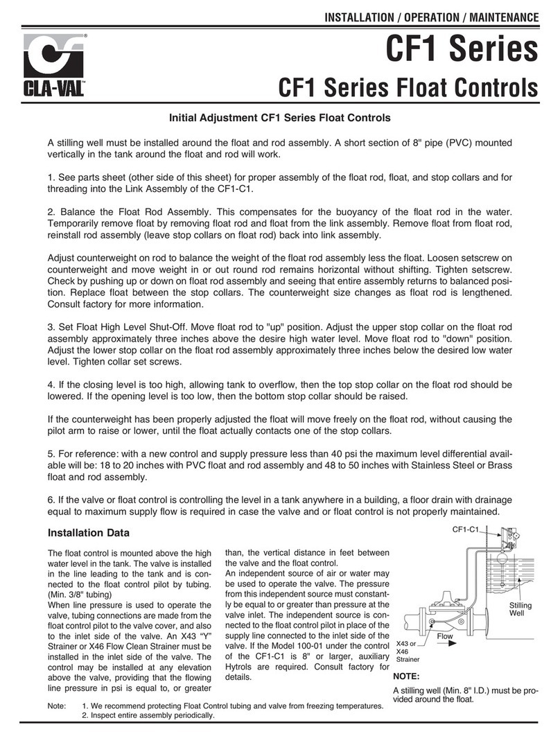
REASSEMBLY
1. Reassembly is in general, the reverse of disassembly.
REASSEMBLY OF BODY ASSEMBLY SECTION
1. Use the wrench flats on stem (11) to hold when tightening hex nut (34).
NOTE: Use caution when using wrenches to tighten the stem and
diaphragm assembly; careful not to damage special carbon coated sur-
faces on stem (11). A light coating of Dow Corning 33 grease, or equiva-
lent, should be applied to stem (11) before reassembly.
2. Clean and replace the Delrin ball (26) if necessary.
CAUTION: Do not overlook replacing this step; this small part plays a
critical role in proper operation of pilot.
3. Lubricate and replace both o-ring’s (41) and o-ring (40); clean and replace
poppet assembly (13) and center sleeve (14); firmly pressing until fitted
flush into upper body (12).
4. Clean surfaces of lower body (8); place on bench with serrations facing up.
5. Install lower body sleeve (18) into lower body (8).
6. Re-assemble the stem and diaphragm assembly that includes the stem
(11), lower diaphragm washer (10), diaphragm (7), o-rings (40 & 41),
upper diaphragm washer (9), lock washer (35) and hex nut (34).
NOTE: Use wrench flats on stem (11) to hold when tightening hex nut (34).
7. Install stem and diaphragm assembly into lower body (8).
8. Install upper body (12).
NOTE: Using the witness marks made in the dis-assembly procedures; to
correctly align the upper body (12) and lower body (8).
9. Install six of the eight bolts (30), six washers (33) and six hex nuts (31);
tightening securely. The remaining two eight bolts (30), two washers (33)
and two hex nuts will be installed later when re-installing the CDS7-DO
back onto the mounting bracket (27).
REASSEMBLY OF UPPER SPRING SECTION
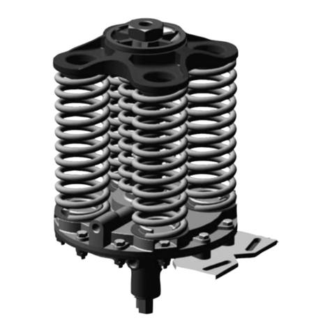
1. Replace spring (19), lower guide (16) and upper guide (17).
2. Inspect, clean & reinstall adjustment stem assembly (20) into cover (15).
3. Clean O-Ring groove of cover (15).
4. Clean, lubricate and install O-Ring (43) into groove of cover (15).
5. Install cover (15) and four screws (32); tightening securely.
NOTE: Re-adjust the adjusting stem assembly (20) clockwise the same
number of turns as recorded in the disassembly instructions above. The
CDS7-DO Altitude Control Delayed Opening will now be reset to the
approximate set point as it was prior to disassembly.
REASSEMBLY OF LOWER SPRING SECTION
1. Install the two spring guides (4); one on each side of spring (19); placing
on top of exposed portion of stem (11).
2. Install cover (5) over spring & guides, installing eight screws (32); tighten-
ing securely.
NOTE: Re-adjust the adjusting screw (2) clockwise the same number of
turns as recorded in the disassembly instructions above. The CDS7-DO
Altitude Control will now be reset approximately for the same reservoir liq-
uid level shut-off point as it was prior to disassembly.
COMPLETING ASSEMBLY
1. Re-install CDS7-DO Altitude Control assembly back onto main valve;
using remaining two remaining bolts (30), two washers (33) and two hex
nuts (3); securely tightening onto bracket (27).
2. Replace previously removed control tube lines & fittings; securely tighten.
SERVICE SUGGESTIONS
INSPECTION
Under normal operating conditions the CDS7-DO Altitude Control will be
trouble free. Visually inspect and check pilot loop for leaks; check for any
continuous leaks from control tube(s), from the vent hole in the lower
cover or side drain port (“D”) on the CDS7-DO pilot.
The volume of drained water from the side drain port (“D”) of the CDS7-
DO pilot will vary according to the valve size. Continuous draining after
main valve has fully opened will indicate a problem. Refer to the service
suggestions to check for probable causes and remedies.
DISASSEMBLY
During preventive maintenance or service to the CDS7-DO Altitude
Control, all pressure to the control must be shutoff. The CK2 isolation
valve in the main valve control lines should be closed before starting dis-
assembly. Main valves 4" and larger have CK2 isolation valves installed,
however main valves smaller than 4" normally do not, therefore requiring
closure of shutoff valves in the main line at the valve inlet and outlet. The
isolation valve in the sensing line to the reservoir must also be closed.
WARNING: Failure to shutoff and release pressure prior to any disassem-
bly can result in serious damage to equipment or injury to personnel.
1. Disconnect and remove all control tubing’s from the CDS7-DO.
2. Remove two of the eight hex nuts (31) washers (33) and bolts (30) that
hold CDS7-DO to the mounting bracket (27).
3. Remove CDS7-DO Altitude Control from main valve to work on a
bench or clean area. Parts must be kept clean.
DISASSEMBLY OF LOWER SPRING SECTION
1. Remove cap (1), loosen hex nut (31) and unscrew adjusting screw (2)
counter clockwise from lower cover (5).
NOTE: Count the number of turns required to remove the adjusting
screw (2) counter clockwise; record this information for future refer-
ence when reassembling. This will allow the CDS7-DO Altitude
Control to be reset back to approximately the same reservoir liquid
level shut-off point, after being reassembled.
2. Loosen and remove the eight cover screws (32).
3. Remove cover (5), two spring guides (4) and spring (19).
DISASSEMBLY OF UPPER SPRING SECTION
1. Remove (22).
NOTE: Count the number of turns currently on the Adjustment Stem
Assembly (20) before removing; record this information for future ref-
erence when reassembling. This will allow the CDS7-DO to be reset
back to approximately the same set-point, after being reassembled.
2. Loosen and remove the four cover screws (32).
3. Remove cover (15), o-ring (43), upper spring guide (17), spring (19)
and lower spring guide (16).
4. Remove poppet assembly (13), center sleeve (14), o-rings (43) & (41).
NOTE: Use caution when using wrenches on poppet assembly (13);
be careful not to damage special carbon coated surfaces.
5. Remove Delrin ball (26).
CAUTION: Use care not to misplace this small part (it is important that
it be re-installed when re-assembling).
DISASSEMBLY OF BODY ASSEMBLY SECTION
NOTE: Before disassembly, apply a witness mark (a punch mark or
scratch) across upper body (12) and lower body (8). The mark is made
on each half of the assembly so that upon re-assembly the marks can
be later lined up in the correct position.
1. Loosen and remove the remaining six hex nuts (31), washers (33) and
bolts (30).
2. Separate the lower body (8) from upper body (12).
3. Remove the stem and diaphragm assembly that includes the stem
(11), lower diaphragm washer (10), diaphragm (7), O-ring (41), upper
diaphragm washer (9), lock washer (35) and hex nut (34).
NOTE: Use the wrench flats on stem (11) to hold when loosening hex
nut (34) to disassemble.
NOTE: Use caution when using wrenches to disassemble the stem
and diaphragm assembly; careful not to damage special carbon coat-
ed surfaces on the stem (11).
4. Inspect all parts for damage, wear and mineral deposits, clean thor-
oughly.
5. Inspect and clean the diaphragm (7); check for wear or cracks; replace
if required.
6. Check O-ring’s (40) and (42) for wear; replace if required. Inspect and
remove any deposits found in O-ring grove areas.
NOTE: Clean all metal parts thoroughly and replace damaged parts as
necessary. If, upon disassembly, sand and silt are found in the CDS7-
DO Altitude Control, every effort must be made to eliminate this prob-
lem. Filters, or relocating the reservoir sensing line may be required if
deposits are found in the sensing chamber of the control.
CLA-VAL
Copyright Cla-Val 2017 Printed in USA Specifications subject to change without notice.
1701
Placentia
Ave
•Costa
Mesa
CA
92627
Phone:
949-722-4800
•Fax:
949-548-5441
•E-mail:
[email protected] •www.cla-val.com
©
N-CDS7-DO (06/2017)
Symptom Probable Cause Remedy
Leak from vent hole
in Lower Cover (5)
Diaphragm (7) damaged Replace
Diaphragm
Hext Nut (34) loose. Tighten Hex Nut
O-Ring (42) or Lower
O-Ring (41) damaged.
Replace O-Rings
(41) and/or (42)
Flow from Supply Port
(S) to Cover Port (1)
restricted.
Silt (foreign matter) in
upper cover.
Clear blockage.
Clean Poppet Assy (13),
and Center Sleeve (14).
Continuous leak from
Vent Port (D).
Main Valve closed.
Silt (foreign matter) in upper
cover, between Poppet Assy
(13) and seating surface of
upper cover (12).
Clean area.
Remove foreign matter.
Upper O-Ring (41) and
O-Ring (43) damaged.
Replace Upper O-Ring (41)
and O-Ring (43)
Continuous leak from
Vent Port (D).
Main Valve open.
Hytrol Main Valve Diaphragm
is damaged or Main Valve
Stem Nut loose.
Service Hytrol Main Valve.
Replace Main Valve
Diaphragm or tighten nut. *
*NOTE: Refer to 100-01 Hytrol IOM for detailed main valve disassembly/ reassembly instructions
