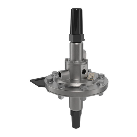
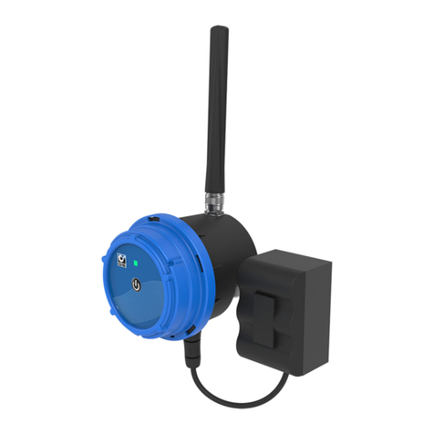
CLA-VAL CRD-34 User manual

Visit www.cla-valpacic.com for more details. Contact the Factory at info@cla-valpacic.com
1
Setup Guide
CRD34 Actuator
PACIFIC
Visit www.cla-valpacic.com for more details. Contact the Factory at info@cla-valpacic.com
Set Up
Guide
CRD34 Actuator
Stuart Brackenridge

1 | Page
CONTENTS Page No
1. Getting connected
a.
Downloading software & firmware 2
b. Installing Cla-Val USB cable (Windows 10) 10-15
c. Connecting to PC 2
2. Important Information on the Display Screen 3
a. System Information
b. Language
c. Continuous Reading
d. Override 4-20mA Input
e. Input and Output display
3. Calibrating the 4-20mA Pressure Range – Statically 4-5
4. Calibrating the 4-20mA Pressure Range – Dynamically 6-7
5. Configuring Actuator On/Off Times and Loss of Signal Default 7
6. Configuring the High and Low Alarm Digital Outputs 8
7. Diagnostic/Troubleshooting LED Status 8
8. CRD34 Wiring Diagram 9
Visit www.cla-valpacic.com for more details. Contact the Factory at info@cla-valpacic.com

Visit www.cla-valpacic.com for more details. Contact the Factory at info@cla-valpacic.com
2
2 | Page
Getting Connected
Note! Before attempting to connect to the CRD34, please ensure you have the latest
Software and Firmware installed on your laptop.
1. Go to website: www.cla-val.ch
2. Click on ‘Download’ located down the left-hand side (Fig 1.)
3. Click on ‘E-Line’ on the taskbar across the top right-hand side of the screen (Fig 2.)
4. Download ‘Cla-Val Driver USB’ Software and Firmware to your PC (Fig 3.)
5. Download ‘e-CPC-34/e-Drive-34’ Software and Firmware to your PC (Fig 4.)
**
It is important that you do not allow Windows to install the USB Driver as the cable will not function correctly when
connected. If you have Windows 10 on your PC, please follow the instructions on pages 3, 4 & 5 on this document**
The e-CPC-34/e-Drive-34 icon will appear on your PC desktop.
6. With the USB lead installed and connected to the PC and CRD34 click on the icon to open the software
7. When the software opens it will display the detail of the unit you are connected to. Click on this detail.
Fig 1.
Fig 2.
Fig 3. Fig 4.
Page 1
Page 2

Visit www.cla-valpacic.com for more details. Contact the Factory at info@cla-valpacic.com
3
3 | Page
Important Information on the Display Screen
1. Check box – Continuous Reading.
a. This allows you to see on the graph where the actuator is currently positioned across
its 4-20mA range (Orange Square)
b. The graph shows the min and max scaling limits of the pressure range (Green Circles)
c. The graph shows the current low and high alarm settings (Blue Squares)
2. Check box – Override Setpoint Activated
a. By typing in a 4-20mA value into the box to the right (such as 12) the actuator will
begin to move to this new pressure setpoint
3. Input and Output Information
a. displays the current milliamp input signal from your manual override setpoint
b. displays the current milliamp feedback signal from the CRD34 actuator
c. displays the current pressure values in bar and PSI
Language Select System Information

Visit www.cla-valpacic.com for more details. Contact the Factory at info@cla-valpacic.com
4
4 | Page
**LED on actuator begins to blink RED & GREEN**
Statically Calibrating the CRD34 Actuator 4-20mA Pressure Range
NOTE! In order to perform a Static Calibration, the current downstream pressure value
must be known plus the spring rating inside the pilot!!
1. Firstly, click ‘Set Range’ on the taskbar to open the calibration screen. A message will appear
warning you that you are going into the calibration mode, click OK.
2. Check the box named; CRD/CRL/CDHS/CDB/CRA
3. Select ‘Static Calibration’ from the drop-down menu and select the pressure units (if required)
4. There is a list of spring pressure ratings denoting the pressure change per each 360 Degree
adjustment of the CRD pilot. Please ensure you know what spring rating is inside the pilot.
5. To work out the number of turns to achieve both high and low pressure from current pressure
value, please see example below.
Using a 1.4 to 7.2 bar spring = 0.8 bar pressure change for every 360-degree turn.
The current downstream pressure is 3 bar and you wish to set the low pressure at 2 bar and high
pressure at 4.2 bar
Formula for low pressure: - Formula for high pressure: -
3 bar – 2 bar = 1.0 bar = 1.25 turns to low 4.2 bar – 3 bar = 1.2 bar = 1.5 turns to high
0.8 bar 0.8 bar
Visit www.cla-valpacic.com for more details. Contact the Factory at info@cla-valpacic.com
5
5 | Page
Continued…
6. Once the high and low values have been established, they need to be entered in the boxes
immediately to the right of &
7. You can also type in your new pressure range in the boxes to the left.
8. Click on to write these values to the actuator. Done!
9. A message will appear – Calibration Done! Click OK.
Note! If you need to adjust the actuator in order to
commission the PRV you can do so by clicking on
the & tabs to set the downstream pressure.
**PLEASE DO THIS BEFORE ATTEMPTING TO STATICALLY CALIBRATE**

Visit www.cla-valpacic.com for more details. Contact the Factory at info@cla-valpacic.com
6
6 | Page
**LED on actuator begins to blink RED & GREEN**
Dynamically Calibrating the CRD34 Actuator Pressure Range – High and Low
Note! This method of calibration can only be performed if the PRV is able to be
operated fully between the new high and low pressure set points.
Preparation:-
Ensure there is a pressure gauge installed downstream of the valve
1. Firstly, click ‘Set Range’ on the taskbar to open the calibration screen. A message will appear
warning you that you are going into the calibration mode, click OK.
2. Check the box named; CRD/CRL/CDHS/CDB/CRA
3. Select ‘Dynamic Calibration’ from the drop-down menu and select the pressure units (if required)
4. Using the begin to drive the motor to adjust the outlet
pressure on the PRV. When the minimum pressure setting is reached click on
5. Then click on to calibrate the low pressure 4mA.
The 4. Adjust valve to 4mA value is highlighted in green.
6. Using the begin to drive the outlet pressure up until the desired maximum
pressure setting is reached, click on
7. Then click on to calibrate the high pressure 20mA.
The 5. Adjust valve to 20mA value is highlighted in red.
8. Type the high and low pressure values in the boxes underneath ‘bar’.

Visit www.cla-valpacic.com for more details. Contact the Factory at info@cla-valpacic.com
7
7 | Page
Continued…
9. Click on
10. A message will appear Calibration Done! Click OK.
Note! If you overshoot the pressure you can use the
to fine tune
the outlet pressure
Configuring the Actuator Speed and Loss of Signal
1. Click on ‘Configuration’ on the task bar
2. To set the Actuator rotation speed enter (if not controlled via SCADA) enter a time in seconds
in each of the windows for time on and time off – (a good actuation speed is 1 second on 5
seconds off – if 0 and 0 are selected the actuator runs continuously)
3. To set the default position of the actuator if the 4-20mA input signal is lost, click one of the
boxes for preference.
4. In either case – click on to upload this information to the actuator

Visit www.cla-valpacic.com for more details. Contact the Factory at info@cla-valpacic.com
8
8 | Page
Setting the Low and High Level Alarms
1. Click on ‘Alarms’ on the taskbar
2. Enter a % value in box highlighted for upper and lower limits for an alarm relay output
3. Click on ‘Write Alarms’ to upload to the actuator
Diagnostic for the LED
At start-up, the LED remains red for 5 seconds, then switches to blinking green.
Solid Green - Status OK, USB cable connected on the maintenance port.
Blinking Green - Status OK, normal operation
No light - Check 24VDC power supply.
Red – 1. Exceed high torque limit - Power down and power up again.
- 2. Excess voltage (above 32 Volts).
- 3. Update firmware (please wait until update is finished).
Blinking Red/Green – 1. Actuator in calibration mode
- 2. Calibration was not completed correctly - recalibrate.

Visit www.cla-valpacic.com for more details. Contact the Factory at info@cla-valpacic.com
9
9 | Page
Wiring Diagram
Code Function Colour
0V
-
Connect to ground (neg
ative
)
Black
24V + Power supply (positive) Red
+ 4
-
20mA
Actuator Pressure Feedback
Green
Common
4
-
20mA loop and push button
Pink
+ 4
-
20mA
Command Signal (set
-
point)
Yellow
-
4
-
20mA
Command Signal
(set
-
point)
Grey
Alarm 1 Actuator LOW relay - input Brown
Alarm 1
Actuator LOW relay
-
output
Blue
Alarm 2 Actuator HIGH relay - input Orange
Alarm 2
Actuator HIGH relay
-
out
put
White
Manual 1
*Decrease actuator
–
push button
Turquoise
Manual 2 *Increase actuator – push button Purple
*Actuator can only be manually overridden when the milliamp supply is removed from the
command signal (yellow & grey)

Visit www.cla-valpacic.com for more details. Contact the Factory at info@cla-valpacic.com
10
10 | Page
Installing Cla-Val USB (Windows 10)
To install the Cla-Val USB cable if you have Windows 8.1 or 10 you must first ‘Disable the Driver
Signature Verification’.
To do this you need to get into the Troubleshooting options from the boot manager.
Simply select Restart from the power options menu (on Windows 8 that’s under Charms or on the
login screen, and in Windows 10 it’s on the Start Menu).
Hold down the SHIFT key while you click Restart.
Once your computer has rebooted you will be able to choose the Troubleshoot option.
Then click on Advanced options.

Visit www.cla-valpacic.com for more details. Contact the Factory at info@cla-valpacic.com
11
11 | Page
Then Startup Settings.
Since we are modifying boot time configuration settings, you will need to restart your Computer one
last time. Click Restart.
Finally, you will be given a list of startup settings that you can change. The one we are looking for is
“Disable driver signature enforcement”. To choose the setting, you will need to press the F7 key.
Your PC will then reboot and you will be able to install unsigned drivers without any error message

Visit www.cla-valpacic.com for more details. Contact the Factory at info@cla-valpacic.com
12
12 | Page
Open your ‘Device Manager’ then plug the Cla-Val USB cable in to your laptop and look under
‘Ports(COM & LPT) to see which USB Serial Device comes up. (This case it’s COM4)
Right click on it and select Update driver software.
Select – ‘Browse my computer for driver software’ option

Visit www.cla-valpacic.com for more details. Contact the Factory at info@cla-valpacic.com
13
13 | Page
Select – ‘Let me pick from a list…’ option
Select – Have Disk
Select ’C\Program Files(x86)\CLA-VAL\Multi-USB Driver 64 Setup’ from the drop down menu. Or
wherever you saved the file on software installation. Click on it.

Visit www.cla-valpacic.com for more details. Contact the Factory at info@cla-valpacic.com
14
14 | Page
’C\Program Files(x86)\CLA-VAL\Multi-USB Driver 64 Setup’ should now be displaying as below. Click
OK.
It should now display as below. Click Next.
This Security Warning will pop up. Click ‘Install this driver software anyway’.

15 | Page
This screen will now pop up. Click ‘Close’
In ‘Device Manager’ you should now see ‘CLA-VAL Multi-USB Interface’ shown under ‘Universal Serial
Bus Controllers’ each time you connect the ‘Cla-Val USB lead’
PACIFIC
AUTOMATIC CONTROL VALVES
45 KENNAWAY ROAD
WOOLSTON
CHRISTCHURCH 8023
!"#$%#"&
#'()*+(,-&!).(/)0&%+0123&4)/&5).6&7,00,.8
!"#$%#"&'#()*)(
+,&-.//#0#1 23#45&633"783/5&!9:)78(9;:(95&<.0&=.#"#/4
>."?&@A+&BCDE&FA+&+GAC
H$I#)"?J#(7#".7K("#$L#"M(3N
6?&000M("#$L#"J#()*)(M(3N
Cla-Val Pacic
45 Kennaway Road, Woolston, Christchurch
Tel: +64 (0)3 964 4860
Email: aspacsales@cla-val.com
www.cla-valpacic.com
!"#$%#"&
#'()*+(,-&!).(/)0&%+0123&4)/&5).6&7,00,.8
Table of contents
Other CLA-VAL Controllers manuals

CLA-VAL
CLA-VAL D35 User manual

CLA-VAL
CLA-VAL 34 Series Owner's manual

CLA-VAL
CLA-VAL CRL-60 Instruction manual

CLA-VAL
CLA-VAL CRL Instruction manual

CLA-VAL
CLA-VAL 130VC-2 Owner's manual

CLA-VAL
CLA-VAL VC-22D User manual

CLA-VAL
CLA-VAL PC-22D Instruction manual

CLA-VAL
CLA-VAL CPC Owner's manual

CLA-VAL
CLA-VAL CDS7-DO Instruction manual

CLA-VAL
CLA-VAL CF1-C1 User manual
Popular Controllers manuals by other brands

Danfoss
Danfoss VLT Micro Drive FC 51 Series Programming guide

Savant
Savant SmartControl RS232 Quick reference guide

Monicon
Monicon GTR-168 manual

Emerson
Emerson PMAC II Solo Installation and operation manual

Crestron
Crestron CH-HREL8-D6 Operation guide

cashco
cashco P3 Installation, operation & maintenance manual