manuals.online logo
Brands
  1. Home
  2. •
  3. Brands
  4. •
  5. CLA-VAL
  6. •
  7. Controllers
  8. •
  9. CLA-VAL CF1 Series Owner's manual

CLA-VAL CF1 Series Owner's manual

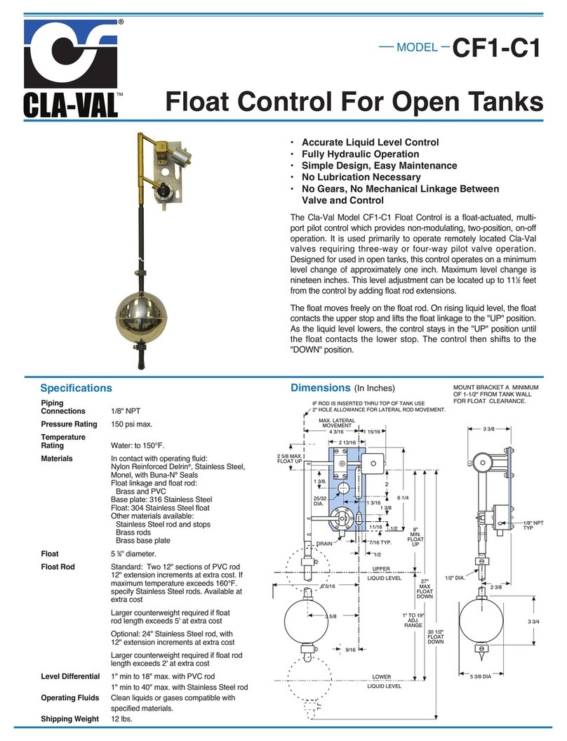
CF1 Series Float Controls
CF1 Series
INSTALLATION / OPERATION / MAINTENANCE
Initial Adjustment CF1 Series Float Controls
A stilling well must be installed around the float and rod assembly. A short section of 8" pipe (PVC) mounted
vertically in the tank around the float and rod will work.
1. See parts sheet (other side of this sheet) for proper assembly of the float rod, float, and stop collars and for
threading into the Link Assembly of the CF1-C1.
2. Balance the Float Rod Assembly. This compensates for the buoyancy of the float rod in the water.
Temporarily remove float by removing float rod and float from the link assembly. Remove float from float rod,
reinstall rod assembly (leave stop collars on float rod) back into link assembly.
Adjust counterweight on rod to balance the weight of the float rod assembly less the float. Loosen setscrew on
counterweight and move weight in or out round rod remains horizontal without shifting. Tighten setscrew.
Check by pushing up or down on float rod assembly and seeing that entire assembly returns to balanced posi-
tion. Replace float between the stop collars. The counterweight size changes as float rod is lengthened.
Consult factory for more information.
3. Set Float High Level Shut-Off. Move float rod to "up" position. Adjust the upper stop collar on the float rod
assembly approximately three inches above the desire high water level. Move float rod to "down" position.
Adjust the lower stop collar on the float rod assembly approximately three inches below the desired low water
level. Tighten collar set screws.
4. If the closing level is too high, allowing tank to overflow, then the top stop collar on the float rod should be
lowered. If the opening level is too low, then the bottom stop collar should be raised.
If the counterweight has been properly adjusted the float will move freely on the float rod, without causing the
pilot arm to raise or lower, until the float actually contacts one of the stop collars.
5. For reference: with a new control and supply pressure less than 40 psi the maximum level differential avail-
able will be: 18 to 20 inches with PVC float and rod assembly and 48 to 50 inches with Stainless Steel or Brass
float and rod assembly.
6. If the valve or float control is controlling the level in a tank anywhere in a building, a floor drain with drainage
equal to maximum supply flow is required in case the valve and or float control is not properly maintained.
Installation Data
The float control is mounted above the high
water level in the tank. The valve is installed
in the line leading to the tank and is con-
nected to the float control pilot by tubing.
(Min. 3/8" tubing)
When line pressure is used to operate the
valve, tubing connections are made from the
float control pilot to the valve cover, and also
to the inlet side of the valve. An X43 “Y”
Strainer or X46 Flow Clean Strainer must be
installed in the inlet side of the valve. The
control may be installed at any elevation
above the valve, providing that the flowing
line pressure in psi is equal to, or greater
than, the vertical distance in feet between
the valve and the float control.
An independent source of air or water may
be used to operate the valve. The pressure
from this independent source must constant-
ly be equal to or greater than pressure at the
valve inlet. The independent source is con-
nected to the float control pilot in place of the
supply line connected to the inlet side of the
valve. If the Model 100-01 under the control
of the CF1-C1 is 8" or larger, auxiliary
Hytrols are required. Consult factory for
details.
NOTE:
A stilling well (Min. 8" I.D.) must be pro-
vided around the float.
Stilling
Well
Flow
CF1-C1
X43 or
X46
Strainer
Note: 1. We recommend protecting Float Control tubing and valve from freezing temperatures.
2. Inspect entire assembly periodically.
13
18
12
11
15
16
17
14
9
10
8
7
5
4
2
1
7
8
OPERATION
FLOAT POSITION PORT 1 PORT 2
Up Pressure To Drain
Down To Drain Pressure
Float Control
CF1-C1
19
4
5
6
8
3
Float
Rod
Assembly
Pilot &
Bracket
Assembly
7
9
10
7
8
CLA-VAL
Copyright Cla-Val 2013 Printed in USA Specifications subject to change without notice.
P.O. Box 1325 •Newport Beach, CA 92659-0325 •Phone: 949-722-4800 •Fax: 949-548-5441 •E-mail: [email protected] •Website cla-val.com
©
PL-CF1-C1 (R-05/2013)
PARTS LIST
NOTE:
1. A stilling well (Min. 8" I.D.) must be provided
around the float.
2. Inspect float and float assembly periodically.
ITEM DESCRIPTION PART No.
1Link Assembly, BRS V8316B
2Cotter Pins (2 required) 20175227D
3Float Rod Assembly (2 ft.)
(Item No. 4 thru 9), PVC 8829902K
4Upper Float Rod (1 ft.), PVC 88298F
Upper Float Road (2 ft.) PVC Consult Factory
5Stud (Required for connecting upper and lower
rods and on for each extension rod), BRS 88264H
6Extension Float Rod (1 ft.), PVC 88297H
Extension Float Rod (2 ft.), PVC Consult Factory
7Stop Collar (2 required), PVC 38097C
8Set Screw (1 for ea Stop Collar), SS 6798837J
9Lower Float Rod (1 ft.) 88292J
Lower Float Rod (2 ft.) Consult Factory
10 Float Ball Stainless Steel (Standard) C0648A
10 Float Ball, Plastic (Optional) Consult Factory C9253A
11 Base and Mounting Plate (316) V6369A
12 Pilot Valve Assembly CF1-C1 10529G
13 Machine Screw 6/32 x 1-1/2” (6 req’d) 6757530J
14 Hex Nut 6/32 (6 req’d) 678206K
15 Counter Balance Bracket Assembly, BRS 45569B
16 Machine Screw 10/32 x 9/16” (4 req’d) 6757822K
17 Hex Nut 10/32 (4 req’d) 6779506C
18 Counterweight (varies with rod length, includes
set screw), Steel, Zinc Plated - Consult Factory
1-5’ PVC Rod
20160501C
19 Pilot & Bracket Assembly CF1-C1, Std Material 89016A
(Less Ball, Rod & Counterweight)
When ordering parts,
please specify:
• All nameplate data
• Description
• Item Number

This manual suits for next models

1

Other CLA-VAL Controllers manuals

CLA-VAL CRD-34 User manual

CLA-VAL

CLA-VAL CRD-34 User manual

CLA-VAL VC-22D User manual

CLA-VAL

CLA-VAL VC-22D User manual

CLA-VAL CRL-60 Instruction manual

CLA-VAL

CLA-VAL CRL-60 Instruction manual

CLA-VAL CRL Instruction manual

CLA-VAL

CLA-VAL CRL Instruction manual

CLA-VAL CF1-C1 User manual

CLA-VAL

CLA-VAL CF1-C1 User manual

CLA-VAL CPC Owner's manual

CLA-VAL

CLA-VAL CPC Owner's manual

CLA-VAL CDS6 Owner's manual

CLA-VAL

CLA-VAL CDS6 Owner's manual

CLA-VAL VC12 User manual

CLA-VAL

CLA-VAL VC12 User manual

CLA-VAL D35 User manual

CLA-VAL

CLA-VAL D35 User manual

CLA-VAL VC-22D User manual

CLA-VAL

CLA-VAL VC-22D User manual

CLA-VAL 34 Series Owner's manual

CLA-VAL

CLA-VAL 34 Series Owner's manual

CLA-VAL PC-22D Instruction manual

CLA-VAL

CLA-VAL PC-22D Instruction manual

CLA-VAL 130VC-2 Owner's manual

CLA-VAL

CLA-VAL 130VC-2 Owner's manual

CLA-VAL 90G-21 Instruction manual

CLA-VAL

CLA-VAL 90G-21 Instruction manual

CLA-VAL CDS7-DO Instruction manual

CLA-VAL

CLA-VAL CDS7-DO Instruction manual

CLA-VAL e-Drive-34 User manual

CLA-VAL

CLA-VAL e-Drive-34 User manual

Popular Controllers manuals by other brands

Carel EVD4 user manual

Carel

Carel EVD4 user manual

EG&G ORTEC 403A instruction manual

EG&G

EG&G ORTEC 403A instruction manual

Compaq Smart Array 221 user guide

Compaq

Compaq Smart Array 221 user guide

NOCO Genius BOOST PRO GB150 User guide & warranty

NOCO Genius

NOCO Genius BOOST PRO GB150 User guide & warranty

Monacor img Stage Line STROBE-1C manual

Monacor

Monacor img Stage Line STROBE-1C manual

Tech Controllers EU-24 SIGMA user manual

Tech Controllers

Tech Controllers EU-24 SIGMA user manual

LAE AC1-27 Series Instructions for use

LAE

LAE AC1-27 Series Instructions for use

MAKOT MCH-07 Series user manual

MAKOT

MAKOT MCH-07 Series user manual

Brightlink BL-VW33-4K60-GUI user manual

Brightlink

Brightlink BL-VW33-4K60-GUI user manual

Basler AVC63-4 Instructions for use

Basler

Basler AVC63-4 Instructions for use

Danfoss PVE Series installation guide

Danfoss

Danfoss PVE Series installation guide

dixell XC650C instruction manual

dixell

dixell XC650C instruction manual

Endress+Hauser RA33 Brief operating instructions

Endress+Hauser

Endress+Hauser RA33 Brief operating instructions

Dataprobe iBootBar iBP-N15 Installation and operations

Dataprobe

Dataprobe iBootBar iBP-N15 Installation and operations

LSIS XBC-DN32U user manual

LSIS

LSIS XBC-DN32U user manual

Edge Lighting CDP installation instructions

Edge Lighting

Edge Lighting CDP installation instructions

National Instruments PXIe-8106 installation guide

National Instruments

National Instruments PXIe-8106 installation guide

Mitsubishi Electric MELSEC iQ-R Series user manual

Mitsubishi Electric

Mitsubishi Electric MELSEC iQ-R Series user manual

manuals.online logo
manuals.online logoBrands
  • About & Mission
  • Contact us
  • Privacy Policy
  • Terms and Conditions

Copyright 2025 Manuals.Online. All Rights Reserved.