CLAS DM 1501 User manual

clas.com
AUTOMATISK DÄCKVÄXLARE 10"-24" 2
HASTIGHET 400V
AUTOMATIC TIRE CHANGER 10"-24" 2 SPEED
SYSTEM 400V
DM 1501

DM 1501 AUTOMATISK DÄCKVÄXLARE 10"-24" 2 HASTIGHETER 400V
Innan du returnerar produkten av någon anledning (installationsproblem, bruksanvisning,
haveri, tillverkningsproblem...), vänligen kontakta oss.
Kontakta oss:
Du kan kontakta oss via e-post på sav@clas.com eller per telefon på 04 79 72 92 80 eller direkt
på vår webbplats clas.com.
Om du har ändrat dig om du vill köpa produkten, ska du returnera den innan du försöker
installera den.
Before returning this product for any reason (installation problem, instructions for use,
breakdown, manufacturing problem...), please contact us.
Contact :
You can reach us by mail sav@clas.com or by phone +33(0)4 79 72 69 18 or go directly to our
website clas.com
If you have changed your mind regarding your purchase, please return this product before you
attempt to install it.
UPPMÄRKSAMHET
WARNING

DM 1501 AUTOMATISK DÄCKVÄXLARE 10"-24" 2 HASTIGHETER 400V
INLEDNING
Användningsområden
Den här maskinen är utformad för att demontera och montera däck för lätta fordon, kommersiella
fordon och motorcyklar samt däck med hårda sidor (Run Flat...).
Maximal hjuldiameter: 1 180 mm
Maximal hjulbredd: 400 mm
Anmärkning: Använd inte maskinen för andra ändamål än de som tillverkaren har avsett.
Garantin täcker inte skador som orsakats av felaktig användning.
Anteckningar
Varningsetiketter visar att området endast är avsett för behörig personal. Dessa etiketter får inte
tas bort. Eventuella skadade eller saknade etiketter ska ersättas.
Rör inte de rörliga delarna när maskinen är i drift.
Tillverkaren kan inte hållas ansvarig för skador som orsakats av olyckor, olämplig användning,
obehöriga ändringar eller reparationer som utförts av operatörer eller tredje part.
Transport
Maskinen ska transporteras i sin förpackning enligt de anvisningar som finns. Flytta paketet med
hjälp av en lämplig gaeltruck och sätt gaarna på de ställen som anges i figur 1 (Fig.1).
Under transporten måste temperaturen ligga mellan -25° och +55° C.
Försiktighetsåtgärder måste vidtas för att hålla maskinen fri från fukt och för att skydda den mot
stötar och slag.
Innehåll i paketet
Automatisk däcklyft
Stödarm
Tillbehörslåda
Tack för att du har valt DM 1501 automatisk däckväxlare.
Om du följer instruktionerna i denna handbok får du ut det bästa av din maskin, maximal
eektivitet och lång livslängd.
Läs den här handboken noggrant innan du installerar och använder maskinen.
Förvara den på ett säkert ställe för framtida användning.
KONTAKTA OSS FÖR INSTALLATION OCH DRIFTSÄTTNING.
FÖR GARANTIÄNDAMÅL MÅSTE INSTALLATION OCH DRIFTSÄTTNING UTFÖRAS AV EN
FACKMAN.
Fig1

DM 1501 AUTOMATISK DÄCKVÄXLARE 10"-24" 2 HASTIGHETER 400V
COMPOSITON
1. Fjäder för den vertikala armen
2. Handtag för ventillåsning
3. Sexkantigt axel
4. Montering/demontering av huvudet
5. Käka
6. Brickan
7. Pedaler
8. Pedal för kontroll av kedjehjulet
9. Pedal för käftspridare
10. Pedal för bromskloss
11. Pedal för lutning
12. Horisontell pedal
13. Låscylinder
14. Tryckmätare
15. Kolumn
16. Spänncylinder
17. Handtag för avtagningsskyel
18. Lufttillförsel
19. Lufttillförsel
20. Cylinder med avdragare
21. Stripparm
22. Teleskopisk spade för start
23. Däckväxlare
24. Lyftcylinder
25. Mobilt armstöd
26. Förvaringslåda
27. Styrskenor
28. Tryckrulle
29. Stödarm
30. Handtagskontrollventil
31. Däcklyftsskiva
32. Roterande arm
33. Däckpress
2
2
9
9
3
3
0
0
1
1
9
9
1
1
8
8
1
1
7
7
3
3
1
1
1
1
5
5
3
3
2
2
1
1
4
4
1
1
3
3
1
1
2
2
2
2
8
8
3
3
3
3
11002233
2200
11
1111
22
2211
77
55
99
66
33
882222
44
1166
2244
2277
2255
2266
22993300
1199
1188
1177
3311
1155
3322
1144
1133
11222288
3333
1
1
0
0
2
2
3
3
2
2
0
0
1
1
1
1
1
1
2
2
2
2
1
1
7
7
5
5
9
9
6
6
3
3
8
8
2
2
2
2
4
4
1
1
6
6
2
2
4
4
2
2
7
7
2
2
5
5
2
2
6
6

DM 1501 AUTOMATISK DÄCKVÄXLARE 10"-24" 2 HASTIGHETER 400V
TEKNISKA DATA
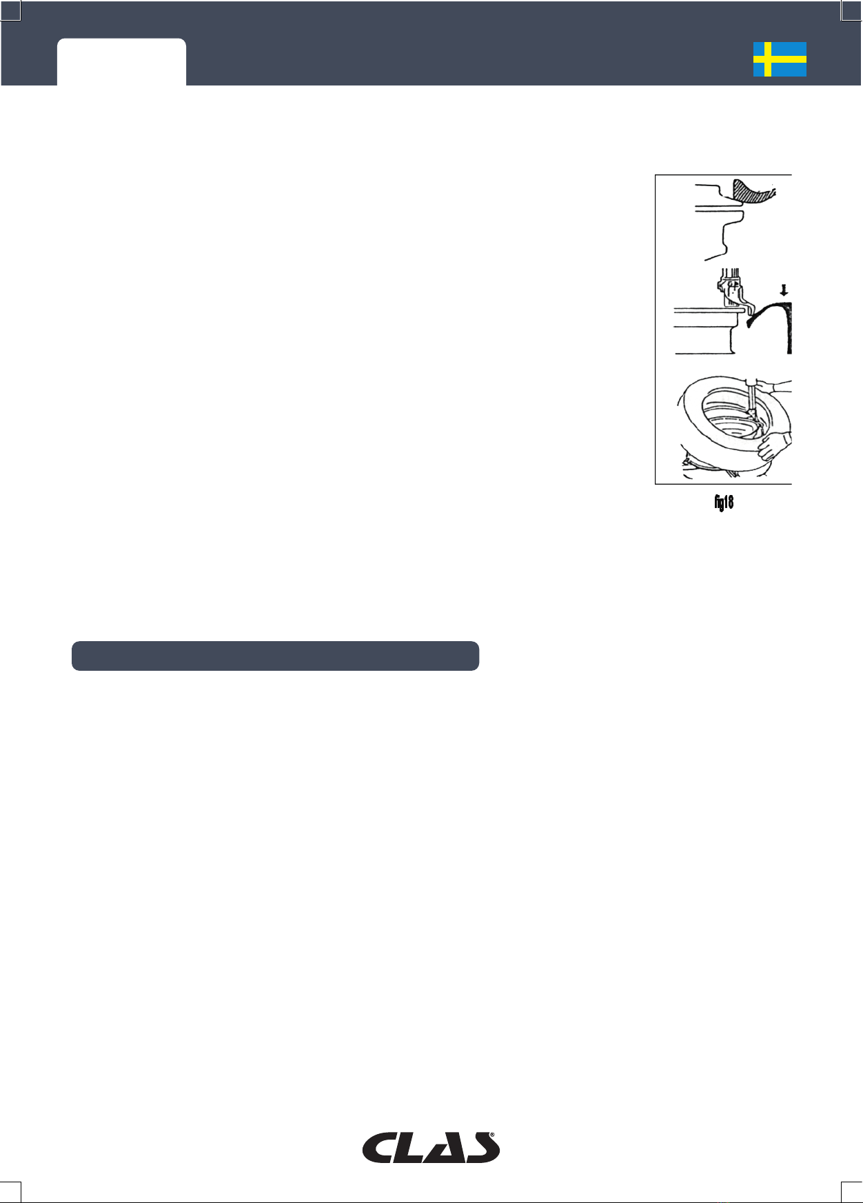
INSTALLATION OCH PROVNING
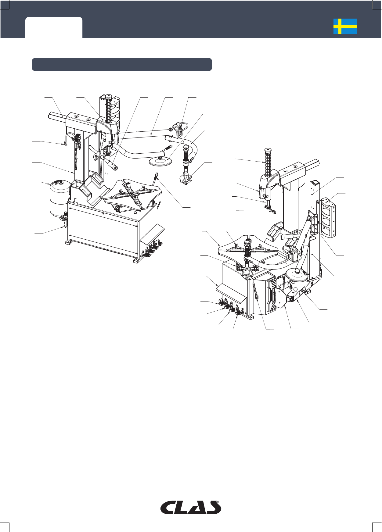
Funktioner :
- horisontell arm som rör sig på en rulle för enkel översättning
- uppblåsare med tryckmätare
- maximal däckdiameter: 1120 mm
- Maximal däckbredd: 3 till 12 tum.
- böjd plattform med säkerhetsanordning som förhindrar klämning
- fälgdiameter utanför greppet: 10 till 21 tum
- fälgdiameter inre grepp: 12 till 24 tum
- 1 hastighet utan omkopplare: Rotationshastighet 1: 6,5 rpm
- ergonomiska och intuitiva pedaler
- Teleskopisk och svängbar avtagsspade i 2 lägen och dubbelverkande cylinder.
- Arbetstryck: 8-10bar
- luftrenare och oljesmörjare
- Säkerhetsventil för slanglös uppblåsning: 3,5 bar.
- bullernivå < 70 dB
- Strömförsörjning: 400V
- Eekt : 0,75kW
- kraft för pärlbrytare: 2500kg
- vikt för däckväxlaren: 315 kg
- Mått: 1850x1800x1980mm
- Standarder: EN 60204-1:2006/AC:2010, 2014/35/EU-direktivet om lågspänning.
Platsområde
Däckmonteringsmaskinens placering måste uppfylla säkerhetsnormerna och operatören måste
ha tillräckligt med utrymme för att kunna använda maskinen och dess komponenter på rätt sätt.
Om maskinen är placerad på ett öppet område är det viktigt att den skyddas under ett skydd.
Maskinen får inte placeras i närheten av brandfarliga gaser, i en fuktig miljö eller i en miljö med
extrema temperaturer. Maskinens yta ska vara skyddad för att förhindra ansamling av damm,
ammoniak och thinner.
Uppackning av
När du har packat upp din däckväxlare ska du kontrollera att den är i gott skick. Kontakta din
återförsäljare om du märker att den har skadats under transporten. Förpackningsmaterial som plast,
spikar, skruvar, trä och kartong ska kasseras i enlighet med gällande återvinningsbestämmelser.
Obs: Det rekommenderas att operatören bär handskar för att undvika skador när maskinen packas
upp.
El- och luftanslutning
Allt elarbete måste utföras av en elektriker. Före all drift måste man se till att kraftkällorna (el och
luft) uppfyller kraven i

DM 1501 AUTOMATISK DÄCKVÄXLARE 10"-24" 2 HASTIGHETER 400V
VARNINGAR
• Placera aldrig benet mellan startspaden och kådan för att undvika skador om du råkar trampa
på fel pedal.
• Placera aldrig handen på däcket när demonteringshuvudet är påslaget, för att undvika skador.
• Placera aldrig handen mellan däcket och greppanordningen när du arbetar på fälgen för att
undvika skador.
• Håll käftarna i stängt läge under pärlbrytningen för att undvika skador.
• Under den slanglösa uppblåsningen rekommenderas operatören att bära skyddsglasögon för att
undvika att stänk når ögonen.
• Placera aldrig handen mellan fälgen och däcket under pumpningen för att undvika skador.
• Låt ingen stå bakom tiltmasten när maskinen är i drift.
specifikationer som beskrivs på maskinens skylt. För att skydda maskinen måste strömförsörjningen
vara utrustad med en drift.
Om strömförsörjningen inte är stabil är det viktigt att installera en spänningsstabilisator mellan
strömkällan och maskinen.
Maskinen ska vara utrustad med en jordledare och en automatisk luftbrytare.
Kontrollera att spänningsvariationen är ±10 %.
Obs: Om nätkontakten saknas rekommenderas att du installerar en som är lämplig för strömmar
över 16 A eller att du ansluter maskinen direkt till strömförsörjningen enligt ovanstående anvisningar.
* Maskiner med 3PH-motor: Efter att ha anslutit maskinen till strömförsörjningen trycker du på
pedalen för att styra bordet (8). Plattan ska rotera medurs. Om den roterar moturs måste två
ledningar vara omvända i trefaskontakten. Eventuella skador som orsakas av att du inte följer
dessa anvisningar täcks inte av tillverkaren.
Anslut kompressorslangen till separatorn.
För att maskinen ska fungera optimalt måste arbetstrycket ligga mellan 8 och 10 bar (110-140 Psi).
Om trycket är lägre än 8 bar (110 Psi) är trycket för lågt för att kalibrera eller ta bort vissa däck.
Det är viktigt att kontrollera att det tryck som indikeras på manometern är tillräckligt. Om inte,
kontrollera slangen eller kompressorn.

DM 1501 AUTOMATISK DÄCKVÄXLARE 10"-24" 2 HASTIGHETER 400V
OPERATIVT TEST
Kontrollera att alla fyra pedalerna är i sitt ursprungliga läge.
Anslut luftkällan: när trycket når 8-10 bar kan driften börja.
Obs: Maskinen är inställd så att käftarna (5) på plåten (6) automatiskt sprids när luftkällan är
ansluten.
Tryck på pedalerna (8): plattan roterar medurs.
Höj pedalen (8): plattan vrider sig moturs.
Tryck på däckkontrollpedalen (10): startspaden (22) börjar röra sig. När du släpper pedalen återgår
spaden till sitt ursprungliga läge. Kontrollera att luftreningssystemet på sidan av maskinen fungerar
som det ska: om du trycker på pedalen 5-6 gånger ska en droppe olja rinna ut. Om oljan flyter för
snabbt eller för långsamt, justera pekfingret med en skruvmejsel.
Tryck på spridarpedalen (9): käftarna (5) på plattan (6) kommer samman. Tryck igen för att sprida
dem isär.
Tryck på knappen på låshandtaget (2) för att låsa både den horisontella och vertikala armen.
Tryck på lutningspedalen (11): masten lutar något bakåt. Tryck på igen för att återföra masten till
sitt ursprungliga läge.
Observera:
- Däckbytaren måste fästas ordentligt så att den inte rör sig under uppblåsningen.
- Maskinen måste vila helt på marken.
- Det är viktigt att koppla bort el- och luftförsörjningen innan du utför underhåll.
- Kontrollera att alla skruvar är ordentligt åtdragna.
- När maskinen används måste vissa försiktighetsåtgärder vidtas: kom inte för nära rörliga delar
och undvik att bära halsband, armband, lösa kläder och långt hår, som kan vara farliga. Operatören
rekommenderas att bära skyddskläder som handskar och glasögon.
- Arbetsområdet bör hållas rent för att minska risken för olyckor.
- Arbetsområdet bör vara tillräckligt upplyst.

DM 1501 AUTOMATISK DÄCKVÄXLARE 10"-24" 2 HASTIGHETER 400V
ANVÄNDA
Det är viktigt att du läser igenom instruktionerna noggrant innan du använder maskinen.
1. Demontering av däcken
Lämna luft i däcket helt och hållet.
Ta bort vikterna från fälgen (fig. 3).
Placera däcket mellan vulkanbrytaren (22) och gummibuert: bladet
ska ligga på vulkanen, 2 cm från fälgen.
Tryck på pedalen (10) för att flytta avslaget från fälgen (fig. 4).
Observera: Däckväxlaren är ursprungligen utformad för lågprofilerade,
styva och breda däck. Ett justeringshandtag gör det möjligt för föraren
att anpassa maskinen när han eller hon arbetar på andra typer av däck.
(Fig. 5)
Rotera däcket och upprepa ovanstående åtgärder tills däcket är helt
utdraget från fälgen.
På plattan finns en linjal som gör det möjligt att placera fälgen korrekt
(fig. 6).
När du har valt låsningsläge (det yttre greppet är särskilt lämpligt för
aluminiumfälgar, det inre greppet används sällan), placerar du hjulet
på plattan. (fig. 7 och 8).

DM 1501 AUTOMATISK DÄCKVÄXLARE 10"-24" 2 HASTIGHETER 400V
2. Låsning av det inre greppet
Tryck på distanspedalen (9) för att justera käftarnas avstånd till fälgens storlek. Placera hjulet på
plattan och släpp försiktigt pedalen (9) tills fälgen är låst.
Tryck på kontrollpedalen (8) för att vrida kedjehjulet (6) medan du smörjer pärlan med en borste.
Var noga med att följa dessa instruktioner för att undvika att pärlan skadas.
Placera den vertikala armen i arbetsläget, för monterings- och demonteringshuvudet nära fälgen,
ca 4-5 mm (fig. 11), och lås sedan armen med låsknappen.
Observera: Monteringshuvudet är tillverkat av ett speciellt material som ger det en idealisk
styvhet. Den är förinställd för att passa standardfälgar. På fälgar från 10 till 18 tum är det därför
inte nödvändigt att ändra vinkeln för montering/demontering. Å andra sidan kräver mindre eller
större fälgar en justering.
Obs: Om maskinen fastnar, stanna omedelbart maskinen och lyft käftspridarpedalen för att vrida
plattan moturs och låsa upp maskinen.
Om det finns en förstärkningsstång i hälen ska du ta bort den
omedelbart. Vrid sedan hjulet för att ta bort den andra sidan av
däcket.
Använd spaken för att placera pärlan på monterings-/
demonteringshuvudet (figur 15). Tryck på fotpedalen (9) för att
vrida plattan medurs och ta bort däcket.
När du har tagit bort vulkanen ska du rengöra fälgen från eventuell
rost eller oxidation och smörja däcket på båda sidor (Figur 16).

DM 1501 AUTOMATISK DÄCKVÄXLARE 10"-24" 2 HASTIGHETER 400V
3. Montering av däck
Obs: Kontrollera att däckets och fälgens dimensioner stämmer överens innan
du monterar dem.
Fäst fälgen på brickan.
Smörj båda sidorna av däcket och fälgen.
Placera demonteringshuvudet (4) vid kanten av fälgen och flytta luftventilen.
Däckets ena sida ska placeras på den övre kanten av monterings-/
demonteringshuvudet (4) medan den andra sidan placeras under, så att
däcket går in i fälgspåret (fig. 18). Tryck på pedalen som styr plattan (8) för
att vrida den medurs och montera den första pärlan på fälgen.
Upprepa ovanstående steg för att montera den övre pärlan.
Obs: Så länge fälgstorleken är densamma behöver du inte vrida på låshandtaget
eller släppa den vertikala armen. Det är bara att trycka på lutningspedalen för
att höja masten.
För att undvika skador får du aldrig lägga handen mellan däcket och käftarna
och aldrig stå bakom maskinen.
Rör inte kompressionsventilen inuti maskinen eftersom detta kan skada
låsventilen.
UNDERHÅLL
Underhåll av däckväxlaren måste utföras av en kvalificerad operatör.
För att maskinen ska kunna användas optimalt och för att förlänga dess livslängd är det viktigt att
den underhålls regelbundet. Underlåtenhet att göra detta kan påverka maskinens prestanda och
tillförlitlighet och kan vara farligt för operatören.
Obs: Det är viktigt att koppla bort el- och luftförsörjningen och att dekomprimera maskinen innan
du utför underhåll.
Maskinen, de rörliga delarna och arbetsområdet måste hållas rena.
Åtgärder för periodiskt underhåll av däckväxlaren :
• Rengör och smörj plattan (6) och käftarna (5) med dieselolja en gång i veckan. Rengör den
vertikala armen och håll den i gott skick.
• Kontrollera oljenivån i lufttankarna regelbundet. Fyll vid behov på med olja nr 20. Tryck på
fotpedalen 5-6 gånger för att släppa ut en droppe olja. Om oljan flyter för snabbt eller för långsamt,
justera skruven.
• Kontrollera och dra åt alla kopplingar och skruvar regelbundet.
• Håll den horisontella armen ren och smörj den regelbundet så att den glider smidigt. facilement.

DM 1501 AUTOMATISK DÄCKVÄXLARE 10"-24" 2 HASTIGHETER 400V
Fig.21
• En gång i veckan ska du smörja alla områden som kan röra sig eller slitas.
• Töm en del av vattnet i kompressorn på en bricka.
• Kontrollera remspänningen och justera vid behov.
Obs: Det är viktigt att koppla bort ström- och luftförsörjningen innan du utför den här åtgärden.
Skruva loss skruven på maskinens vänstra sida för att ta bort panelen och justera muttern för att
lossa eller spänna bältet (Figur 21).
Om den vertikala axeln inte låses ordentligt, fortsätt på följande sätt:
• Koppla ur maskinen.
• Ta bort skyddet för den vertikala armen.
• Justera muttern nära den gängade stången med en skiftnyckel
eller dra åt skruven på baksidan av låsplattan.
• Anslut maskinen igen och kontrollera att den vertikala armen höjs
3-4 mm.
Om den horisontella axeln inte låses ordentligt, fortsätt på följande
sätt:
• Ta bort mastskyddet.
• Justera M6-muttern på båda sidor med en skiftnyckel medan du hanterar armen tills den rör sig
lätt. Dra sedan åt muttern.
• Justera den mellersta skruven med en skiftnyckel och lås den horisontella armen. Dra åt muttern
när armen rör sig 3-4 mm.

DM 1501 AUTOMATISK DÄCKVÄXLARE 10"-24" 2 HASTIGHETER 400V
Elektriskt diagram
Pneumatiskt diagram

DM 1501 AUTOMATIC TIRE CHANGER 10"-24" 2 SPEED SYSTEM 400V
INTRODUCTION
Scope of Application
This DM 1501 machine is designed and made specially for changing the tires of cars, vans, light
trucks and motorcycle with the principle of best quality and highest working eciency, especially
suitable for the sti and low profile tyres.
Max wheel diameter: 1180mm
Max wheel width: 400mm
Note: This machine can only be used for the purpose designed by the manufacturer. Do not use it
for any other purpose.
Any damage caused by incorrect using or beyond the scope of application will not be covered
under warranty.
Note:
Unauthorized people should not stand close to the place with warning stickers and never take o
the stickers.
Never touch the moving parts during the operation.
The damage, due to the accident, misusing, unauthorized changing and repairing of the machine
caused by the operators or the third person, is not in charged by the manufacturer.
Transport
Make sure transport the machine with its original package, and place it according to the
marks on the package. The packed machine should be moved by means of a fork lift truck of
suitable capacity, insert the forks at the points shown in (Fig.1).
The temperature for the transportation should –250 to +550, some measure should be use to
prevent the humidity, shake and concussion.
Packing list
The tire changer
Help arm
Accessory box
Thanks for choosing DM 1501 automatic tire changer. This guide is an important document for
the machine, for ensuring correct and safe operation, and also granting a long working life and
the best eciency to the machine, please read this manual carefully before the installation and
operation.
Carefully keep this manual for use at any time.
INSTALLATION AND COMMISSIONING, PLEASE CONSULT US.
WITHIN THE FRAMEWORK OF THE GUARANTEE, INSTALLATION AND COMMISSIONING MUST
BE CARRIED OUT BY A PROFESSIONAL.
Fig1

DM 1501 AUTOMATIC TIRE CHANGER 10"-24" 2 SPEED SYSTEM 400V
CONTENT
1. Vertical shaft spring
2. Handle valve
3. Hexagon shaft
4. Demount head
5. Claw
6. Turntable
7. Pedal assembly
8. Turntable pedal
9. Clamp claw
10. Tire press pedal
11. Column tilt pedal
12. Horizontal pedal
13. Lock cylinder
14. Pressure gauge
15. Column
16. Clamp cylinder
17. Blade handle
18. Air tank
19. Air source
20. Bead breaking cylinder
21. Bead press arm
22. Bead breaking blade
23. Crowbar
24. Lifting cylinder
25. Mobile carriage
26. Tool box
27. Guide rail
28. Press roller
29. Supporting arm
30. Handle control valve
31. Tire lifting disk
32. Rotating arm
33. Tire press
2
2
9
9
3
3
0
0
1
1
9
9
1
1
8
8
1
1
7
7
3
3
1
1
1
1
5
5
3
3
2
2
1
1
4
4
1
1
3
3
1
1
2
2
2
2
8
8
3
3
3
3
11002233
2200
11
1111
22
2211
77
55
99
66
33
882222
44
1166
2244
2277
2255
2266
22993300
1199
1188
1177
3311
1155
3322
1144
1133
11222288
3333
1
1
0
0
2
2
3
3
2
2
0
0
1
1
1
1
1
1
2
2
2
2
1
1
7
7
5
5
9
9
6
6
3
3
8
8
2
2
2
2
4
4
1
1
6
6
2
2
4
4
2
2
7
7
2
2
5
5
2
2
6
6

DM 1501 AUTOMATIC TIRE CHANGER 10"-24" 2 SPEED SYSTEM 400V
TECHNICAL DATAS
INSTALLATION & TESTING
Specifications:
- roller-supported horizontal arm
- inflator with pressure gauge
- max. wheel diameter: 1120mm
- tire width: 3"-12"
- turntable with anti-pinch device
- outside clamp diameter: 10"-21"
- inside clamp diameter: 12"-24"
- turntable rotation speed: 6.5rpm
- ergonomic foot pedal
- adjustable 2 positions bead breaker blade with protection and double acting cylinder jack
- working air pressure: 8-10bar
- air cleaner and oil lubricator
- tubeless inflator safety valve: 3.5bar
- sound level < 70 dB
- power supply voltage: 400V
- power: 0,75kW
- bead breaker arm power: 2500kg
- tire changer weight: 315kg
- dimensions: 1850x1800x1980mm
- standards: EN 60204-1:2006/AC:2010, 2014/35/EU Low voltage Directive
Installation place
Choose the installation site according to the rules on safety at work. Moreover, the installation
space must allow the operator to use the machine and all its components without any restriction.
In case of the installation is in the open area, it is necessary to protect the machine by means of
a protective shed. Never use the machine in the place with flammable gas, and never place the
machine in the extreme temperature or humidity environment, the surface of the machine should
against lots of dust, ammonia and diluent etc.
Unpacking
After unpack the package, checking the eyeable damage on the machine and the component due
to the shipment, if there is some problems please contact with the dealer. The packing material
such as plastic, nail, screw, wood and carton should be put into the waste box or be handled
according to the local regulations.
Note: The operator should wear the gloves, so as to avoid the injury when unpack the machine.
Power and air connection
Any electrical connection should be done by the specialized technician. Check if the power and air
sources are in accordance with the specification on the nameplate before operation. The electrical
net, with which the machine connected should have a stabilizer to protect the machine.

DM 1501 AUTOMATIC TIRE CHANGER 10"-24" 2 SPEED SYSTEM 400V
WARNING
• Never place leg between the bead breaker blade and bead breaker rubber, so as to avoid stepping
the wrong pedal and injury the operator.
• Never place hand on the tyre when the demount head is on the working position, so as to avoid
the injury of the operator.
• Never place your hand between the tyre and gripping device when operate the rim, so as to
avoid the injury of the operator.
• The jaws should be in closed position when do the bead break, so as to avoid the injury of the
operator.
• The operator should wear the protection glasses when inflate the tyres with the machine with GT
system, so as to avoid something blow into the eyes.
• Never put the hand between the rim and tyre when inflate the tyre, so as to avoid the injury of
the operator.
• There should be nobody behind the tilting post, when the machine is on the working position.
If the voltage is not stable r, a voltage stabilize should be connected between the power source
and the machine.
The machine should be well earthed .An automatic air-switch should be adopted with the main
power supply.
The power voltage only would change +10%.
Note: If there is no power plug on the machine, the user should mount on one, which suitable for
the electric current over 16A or connect the power supply directly according to the above demand.
For the machine with the motor of 3PH, step the pedal (8) after the connection of the power
supply and the turntable (V) should turn in a clockwise direction. If the turntable turn in the
counterclockwise position, reverse any two of the wires in the three-phase plug, the damage
caused by the ignorance of the above instruction, will not be covered by the manufacturer.
Connect the air hose of the air compressor with the tie-in of the separator.
The operating pressure of this machine should be 8-10bar (110-140Psi), the machine can work well
within such operating
pressure, if it is lower than 8bar(110Psi) the strength for the grip and bead break for turntable will
be not enough for some kind of tyres and even it can not operate the tyres.
Check if the reading on the pressure gauge that locates on the separator meet the demand of
pressure setting reading, if not so, check if there is some problems on the hose or air-compressor.

DM 1501 AUTOMATIC TIRE CHANGER 10"-24" 2 SPEED SYSTEM 400V
OPERATING TEST
Check the four pedals are in their original position; connect the air source, the operation can begin
when the pressure up to 8--10bar
Note: After the connection with the air source the clamp (5) on the turntable (6) should automatic
open, which is setted before delivery.
Pressing the pedal (8), the turntable (6) will turn in the clockwise direction.
Raising the pedal (8): the turntable (6) will turn in the counterclockwise direction.
Pressing the pedal (10), the bead breaker blade (22) will begin to move, when the pedal is released
the bead breaker blade returns to its original position. In the meantime please check towards the
body to see if the air regulator works well. Normally it will drop one drop of oil after the pedal is
pressed for 5-6 times, if it drops too quick or too slow, please adjust the index on the air regulator
by a screwdriver.
Pressing the pedal (9), the clamps (5) on the turntable (6) close; (when lightly step the pedal the
machine can show the step moving function). When the pedal is pressed again, the clamps (5)
open.
Press the pneumatic locking button (2), to lock the horizontal arm and vertical arm.
Pressing the pedal (11), the post will tilt back slowly, when the pedal is pressed again, the post will
return to its original position.
Notes:
• The machine must be fixed well to avoid the shake during the operation.
• The machine must place on the ground completely.
• Cut o the air and electric power sources before any maintenance.
• Check the screws on every parts of the machine is tight.
• Keep the human body and hands away from the moving parts of the machine during the
operation. The necklace, bracelet, loose clothes and long hair is dangerous for the operators. The
operator should wear safe clothes such as gloves and glasses.
• Keep the working area tidy and clean, or it may cause sudden accident
• The working area should be well lighted.

DM 1501 AUTOMATIC TIRE CHANGER 10"-24" 2 SPEED SYSTEM 400V
OPERATION
Never use the machine before read this instruction and warning carefully.
Demounting the tyres:
Release all the air inside the tyre.
Remove the weight on the rim (Fig.3)
Place the tyre between the bead breaker blade (22) and rubber pad,
and place the blade on the bead 2 cm from the rim, step on the pedal
(10) to separate the bead from the rim. (Fig. 4)
The wenthole on the tyre should not near to the bead breaker blade
during the operation.
Note: This machine is designed particularly for the low profile, sti and
wide tyres, so there is a adjusting handle on the bead breaker.
When mount or demount the
particular wide tyres, the operator can adjust the handle position and
do the
operation on the wide tyres.(Fig. 5)
Rotate the tyre and repeat the above steps until the tyre is fully extended
from the rim.
A positioning ruler on the plate helps to position the rim correctly (Fig.
6).
Turn the tyre over and repeat the above steps on the other parts of the
tyre until the tyre is fully extended from the rim.
The positioning scale on the turntable directly indicates the position
of the rim (Fig. 6). Place the tyre on the turntable after choosing the
locking method.
Normally, for aluminium alloy rims, outer locking is appropriate, inner
locking is rarely used (Fig. 7 and Fig. 8).

DM 1501 AUTOMATIC TIRE CHANGER 10"-24" 2 SPEED SYSTEM 400V
Inside locking
Pressing the pedal (9) make the 4-clamps closed to the position in accordance with the rim, then
put the tyre on the turntable, release the pedal (9) (release lightly), till the rim locked well.
Press the pedal (8) to turn the turntable (6), dip the prepared lubricator with the brush and
then lubricate the bead while turning,it is easy to damage the bead if do not follow the above
instructions.
Move the vertical arm in the working position, make the mount/demount head close to the bead,
the distance between the mounting head and the rim should be 4-5mm.(Fig. 11), then lock the arm
by press the locking button.
Note: The mount/demount head with good stiness is made of special material and it has been
adjusted before delivery in accordance with the standard rim.
It is not necessary to adjust the angle when it operate the rim
from10" to 18", but if the rim is less or bigger than 10" to 18"
then it needs to be adjusted.
Note: In the event of a blockage, stop the machine immediately
and lift the jaw spreader pedal to rotate the platen
counterclockwise and unblock the machine.
If there is tube inside bead, take out the tube at first. Then turn
over the wheel to demount the other side of the tyre.
Insert the lever to lift the bead on the mount/demount head
(Fig. 15), step the pedal (9) to
turn the turntable clockwise,then
demount the tyre.
After demount the bead, please
clean the rim free from the rust
or oxide, and lubricate both sides
of the bead. (Fig. 16)

DM 1501 AUTOMATIC TIRE CHANGER 10"-24" 2 SPEED SYSTEM 400V
Mounting the tyre
Note: Make sure that the size of the rim and the tire is the same before
mounting.
Clamp the rim on the turntable
Grease both side of the tyre and rim.
Place the demount head (4) on the edge of the rim, and move the air valve
aim at the mount/demount head.(Fig. 17)
Place one side of the tyre on the upside of the tail of the mount/demount
head (4), then press the other side of the tyre under the mount/demount
head (4), to make the tyre enter the groove of the rim. (Fig. 18) Pressing the
pedal (8) to turn the turntable clockwise, and complete mount the bottom
part of the tyre on the rim.
Repeat the above steps to mount the upper bead.
Note: It is not necessary to rotate the locking handle or loose the vertical
arm every time, if the size of the rims is the same, just step the pedal to tilt
backward the post (avoiding the aging of the locking valve).
Do not put your hand between the tyre and clamps and never stand behind the machine, avoiding
body injury.
Never adjust the pressure control valve inside the machine, otherwise the locking valve might be
damaged.
Table of contents
Languages:
Other CLAS Tyre Changer manuals
Popular Tyre Changer manuals by other brands

Atlas Equipment
Atlas Equipment 200 Series Installation & operation manual

Hofmann
Hofmann monty 3550 Operation instructions, Spare parts list

Hunter
Hunter TCA28 installation instructions

Corghi
Corghi Artiglio 5000 Operator's manual

WERTHER INTERNATIONAL
WERTHER INTERNATIONAL HYDRA SA20 Instruction and maintenance manual