manuals.online logo
Brands
  1. Home
  2. •
  3. Brands
  4. •
  5. ClearWater Lights
  6. •
  7. Motorcycle Accessories
  8. •
  9. ClearWater Lights BMW G310R User manual

ClearWater Lights BMW G310R User manual

Page 2
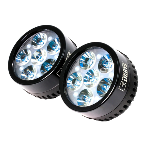
Parts List and Bike Preparation
• Check Parts list below with your kit to be sure all parts are handy. If
something is missing, please call us at (916) 852-7029.
Please be sure to read our instructions thoroughly
before attempting installation.
Page 1
Page 3
Page 2
Step 1: Disassembly
Remove the left and right side bolts pointed out in (Fig. 1) above with
a Phillips screwdriver.
Phillips ScrewdriverPhillips Screwdriver
Fig. 1Fig. 1
The headlgih panel wil pivot downward, as shows above in (Fig. 2).
Fig. 2Fig. 2
• Remove the back seat and set aside.
Bike Preparation:
• First, park the motorcycle on hard pavement or concrete to insure the bike
will be stable during the installation. If you can mount the bike on a stand
with tie-down straps, this will help secure the motorcycle.
• Follow the manufacturers guidelines for disconnecting the battery. This is
important to prevent damage to the electrical system.
Page 4 Page 3
Fig. 5Fig. 5
Remove the two M6 bolts as shown above (Fig. 3) on both sides of the
bike. It is helpful to remove the bolts and install our bracket on one
side at a time.
(Fig. 4) and (Fig. 5) above show what the assembled lights will look like
on the bike.
Fig. 3Fig. 3
5mm Hex Key5mm Hex Key
M5x40 SH (4) M6x14 SHCS Bolt (4)
M6 Flat Washers(4)
#14 Spacer (4)
M5 Flat Washer (4)
Fig. 4Fig. 4
Step 2: Mounting the lights
Page 5
Page 4
Step 3: Wiring
Page 6
Step 3: Wiring
Page 5
NOTE: Before proceeding with wiring the lights, take a moment to review
the wiring diagram. Keep the diagram handy throughout the installation.
Mounting The Volume Control Knob: (Bar Mount)Mounting The Volume Control Knob: (Bar Mount)
• Mount the Volume Control Knob to the handlebar using the
provided“Pot hardware”(refer to the part list on pg. 1). Refer to (Fig. 6)
for proper assembly position.
• Route the Volume Control Knob wire along existing wires, using Zip
Ties to secure it (Fig. 6). Refer to the wiring diagram on page 4.
Fig. 6Fig. 6
Page 7
Step 3: Wiring
Wire Routing:
• Be sure to route wires so that they cannot become tangled or caught
in either a suspension part or steering part. Check movement of both
steering and suspension before riding the bike.
• It is sometimes helpful to follow existing wire routing.
• Using included Zip Ties, mount the wiring harness (small black box) to the
location pointed out in (Fig 9).
Page 6
• With the fuse holder removed, route the black and red power cables
underneath the gas tank through the wiring trough. (You don’t need to
remove the gas tank) (Fig 9).
• Locate the auxiliary plug show in (Fig 8), and tap the thin red wire from the
relay harness to the orange as shown.
• Remove the rubber boot from the headlight connector, exposing the 3-wire
plug underneath. (Fig. 7)
• Using the included Posi-tap, connect the thin white wire from the volume
control knob to the yellow wire on the headlight connector. (See wiring
diagram on page 7)
• Connect the RED wire with the fuse holder and ring terminal to the positive
battery terminal directly in front of the battery. Remove fuse from our harness
before hooking up battery to prevent accidental shorts. (Fig. 9)
• Connect the BLACK wire ring terminal to the negative battery terminal.
• Use a BLUE Posi-Twist to connect the GREEN wire from the volume control
knob to the two GREEN wires from the lights (See wiring diagram on page 4).
(3 wires total).
• Use a BLUE Posi-Twist to connect RED wire from the relay harness to the (2)
RED wires from the lights and the (1) red wire from the volume control knob.
(See wiring diagram on page 4). (4 wires total).
• Again use a BLUE Posi-Twist to connect the (1) BLACK wire from the relay
harness and the (1) BLACK wire from the volume control knob to the (2) black
wires from the lights. (See wiring diagram on page 4). (4 wires total).
Page 8
Step 3: Wiring
Page 7
Tap white wire from volume control knob to this yellow wire.
Mount relay harness inside hereMount relay harness inside here Attach power terminals to battery hereAttach power terminals to battery here
Tap thin red wire from relayTap thin red wire from relay
harness to this orange wireharness to this orange wire
Route power cables under gas tankRoute power cables under gas tank
through wiring troughthrough wiring trough
Fig. 7Fig. 7
Fig. 8Fig. 8
Fig. 9Fig. 9
Page 9
Install Tips & Notes
Aligning the Lights:
Ask an assistant to help you with this
procedure. Make sure the bike is on
level ground and have an assistant sit
on the bike. Press a level against the
face of the light, and adjust its angle.
The goal is to adjust the lights so that
the light is level with the ground.
Passengers and luggage may alter
the alignment of the light, so further
adjustments may be needed. You may
nd that a slight downward angle (5
degrees) is helpful.
Page 8
Do Not Kink The Grommet
Do Not Kink The
Grommet
To maintain the integrity
of the water sealling
grommet, do not kink,
deform or put pressure
on the grommet
when dressing the
wires during install of
Clearwater Lights.
Page 10
Notes
Page 9
Page 11
Notes
Page 10
Revised 6/22/20

Other ClearWater Lights Motorcycle Accessories manuals

ClearWater Lights Billie Brake Light User manual

ClearWater Lights

ClearWater Lights Billie Brake Light User manual

ClearWater Lights Krista User manual

ClearWater Lights

ClearWater Lights Krista User manual

ClearWater Lights CANopener User manual

ClearWater Lights

ClearWater Lights CANopener User manual

ClearWater Lights Glenda User manual

ClearWater Lights

ClearWater Lights Glenda User manual

ClearWater Lights Krista User manual

ClearWater Lights

ClearWater Lights Krista User manual

ClearWater Lights Krista User manual

ClearWater Lights

ClearWater Lights Krista User manual

ClearWater Lights Glenda User manual

ClearWater Lights

ClearWater Lights Glenda User manual

ClearWater Lights Darla User manual

ClearWater Lights

ClearWater Lights Darla User manual

ClearWater Lights Glenda User manual

ClearWater Lights

ClearWater Lights Glenda User manual

ClearWater Lights Glenda User manual

ClearWater Lights

ClearWater Lights Glenda User manual

ClearWater Lights Glenda User manual

ClearWater Lights

ClearWater Lights Glenda User manual

ClearWater Lights BMW K1600GT User manual

ClearWater Lights

ClearWater Lights BMW K1600GT User manual

ClearWater Lights Glenda User manual

ClearWater Lights

ClearWater Lights Glenda User manual

ClearWater Lights Dixie User manual

ClearWater Lights

ClearWater Lights Dixie User manual

ClearWater Lights BMW K1600GT User manual

ClearWater Lights

ClearWater Lights BMW K1600GT User manual

Popular Motorcycle Accessories manuals by other brands

Lone Rider 1250CBB-SEW Care Instructions

Lone Rider

Lone Rider 1250CBB-SEW Care Instructions

KTM 00029920000EB Information

KTM

KTM 00029920000EB Information

mitoredlight LASER HELMET user manual

mitoredlight

mitoredlight LASER HELMET user manual

SRC H-CRF300L-04-01-AL manual

SRC

SRC H-CRF300L-04-01-AL manual

SRC B-TRK502-14-01-SL quick start guide

SRC

SRC B-TRK502-14-01-SL quick start guide

LSL 153T072H FITTING INSTRUCTION

LSL

LSL 153T072H FITTING INSTRUCTION

hepco & becker 6307546 00 01 Mounting instructions

hepco & becker

hepco & becker 6307546 00 01 Mounting instructions

hepco & becker Easyrack Mounting instructions

hepco & becker

hepco & becker Easyrack Mounting instructions

DYNATEK D2K-HD1 User instructions

DYNATEK

DYNATEK D2K-HD1 User instructions

Yoshimura RACE Series manual

Yoshimura

Yoshimura RACE Series manual

hepco & becker 5012524 00 01 quick start guide

hepco & becker

hepco & becker 5012524 00 01 quick start guide

Dakota Digital MCL-30K-SPD Installation

Dakota Digital

Dakota Digital MCL-30K-SPD Installation

ACEBIKES SteadyStand manual

ACEBIKES

ACEBIKES SteadyStand manual

Dynojet Power commander V installation guide

Dynojet

Dynojet Power commander V installation guide

SW-Motech HTA.00.682.15000 Mounting instructions

SW-Motech

SW-Motech HTA.00.682.15000 Mounting instructions

SIGNIFY EA2306 instruction manual

SIGNIFY

SIGNIFY EA2306 instruction manual

AKE Bluetooth helmet set 101 Operating and installation instructions

AKE

AKE Bluetooth helmet set 101 Operating and installation instructions

Ohlins HO 360 Mounting instructions

Ohlins

Ohlins HO 360 Mounting instructions

manuals.online logo
manuals.online logoBrands
  • About & Mission
  • Contact us
  • Privacy Policy
  • Terms and Conditions

Copyright 2025 Manuals.Online. All Rights Reserved.