The L10 Ultrablade Pro LED Exit (LUBPRO) is a recessed ceiling mount fitting. The LUBPRO can be
attached directly to any solid surface, or to a ceiling tile with the integrated clamping mechanisms. The
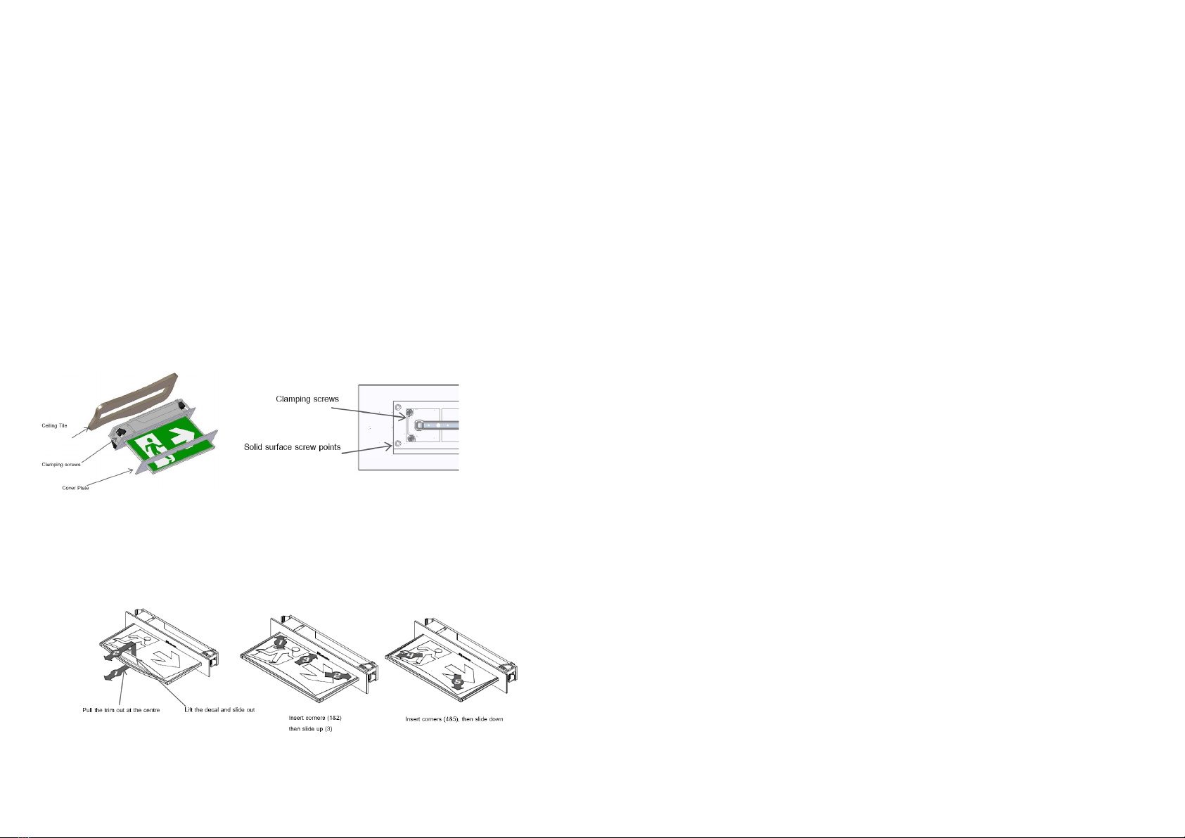
LUBPRO comes with an attached Flex. Please follow the steps below to install the LUBPRO Exit:
•Create a cut-out (350mm x 48mm) in the mounting surface.
•Route the power cord to the mains connection and connect the 240VAC supply.
•Insert the LUBPRO into the ceiling cavity tighten the (4) clamping screws.
•Alternately, fix the LUBPRO to a solid surface using (4) screws through the surface material.
•Install the cover plate.
•For Rod Suspended (LUBPRO-RS) see 1942468_xUBPRO-RS-xx Installation Supplement
•Apply power to the fitting and test.
•If the external flexible cable or cord of this luminaire is damaged, it shall be exclusively replaced by
the manufacturer or his service agent or a similar qualified person to avoid a hazard.
•Terminal block not included. Installation may require advice from a qualified person.
•Recommended specifications of terminal block for connecting leads:
−Type of Terminal: Screw Terminal
−Number of Terminals: 3-Pin
−Rated Voltage: 250 V
−Rated Connecting Capacity: 10A
•If the CTP capabilities are activated, please affix the CTP Status Label to a visible surface.
Luminaire Dimensions: 380mm x 220mm
Cover Plate: 385mm x 67mm
Ceiling Cut-out: 350mm x 48mm
Minimum Depth 80mm
Changing EXIT Legend Inserts:
The Ultrablade Pro Exit comes with an assortment of standard legends.
1. To remove the legend, grasp the centre of the bottom trim piece and pull down slightly to expose the legend edge.
See photo.
2. Grasp the bottom edge of the legend and slide the existing legend out of the blade, while working the edges out
along the sides.
3. Slide the new legend into the blade, ensuring to fit the edges into the sides then slide the legend to the top of the
blade. Insert one bottom corner then the other. Slide the legend down into the bottom trim.
This luminaire (with reinforced insulation between control/LED terminal and AC supply) contains non-
user replaceable light source and battery - to be replaced (if required, refer installation instructions for
battery replacement) by Clevertronics service personnel/agents or a registered electrician.
1. Prior to any work, isolate the power to the luminaire that requires battery replacement
2. Remove Cover Plate, and either remove Solid surface screws or turn Clamping screws anti-
clockwise to remove fitting.
3. Remove cover and remove cable ties holding the battery and remove the Battery Connector from
the Emergency Driver.
4. Replace battery, connect to Emergency Driver and secure with cable ties.
5. Replace cover and reinstall the fitting, including the faceplate.
1. Prior to any work, isolate the power to the luminaire that requires battery replacement
2. Remove Cover Plate, and either remove Solid surface screws or turn the four Clamping screws
Anti-clockwise to remove fitting.
3. Remove cover and remove cable ties holding the battery and remove the Battery Connector from
the Emergency Driver.
4. Disconnect the signal cable from LED strip, loosen screw and remove the Emergency Driver.
5. Remove 4 self-tapping screws and unclip the LED strip.
6. Install the new LED strip, then following the above procedure in reverse.
Testing Procedure:
When the unit is connected to the un-switched active, it must be allowed to charge the battery for at least
24 hours. Conduct the following tests:
•The emergency lamp must illuminate for at least 180 min after disconnection from the mains. The
results of all tests are required to be recorded in a service logbook, which is to be kept on-site at all
times. If the unit fails to illuminate for the requisite time, remedial action must be taken to repair the
situation and once completed, the unit must pass a subsequent test.
•Press and hold Test Button or switch Off Mains Supply, check that the emergency lamp is On.
•Release the Test Button or Switch On Mains Supply, check that the emergency lamp is Off (Non-
maintained operation).
Below are a list of common problems and their possible causes.
Fault: The Green LED Test Switch indicator is not illuminated.
Check: A.C. is connected and is turned on.
Battery is connected
Test Switch for damage.
Fault: Lamp does not illuminate in emergency mode.
Check: A.C. is connected.
Lamp is correctly inserted.
Battery is connected
Fault: Lamp illuminates in emergency mode, but only stays on for a short period.
Check: Battery has been allowed to charge for at least 24 hours.
Caution:
On many building sites, power circuits may be cut off in an uncontrolled and repetitive basis during
construction. As a result, any Exit & Emergency Units, on these circuits, will have their batteries
discharged or “cycled”. The Li-ion battery in the luminaire has been selected to give excellent long life
performance in a controlled IEC 60598-2-22 testing environment. Excessive battery cycling will reduce
through-life performance and may lead to premature battery failure. Battery warranty claims, as a result
of such abuse, are specifically EXCLUDED from Clevertronics warranty terms.


