manuals.online logo
Brands
  1. Home
  2. •
  3. Brands
  4. •
  5. Comelit
  6. •
  7. Intercom System
  8. •
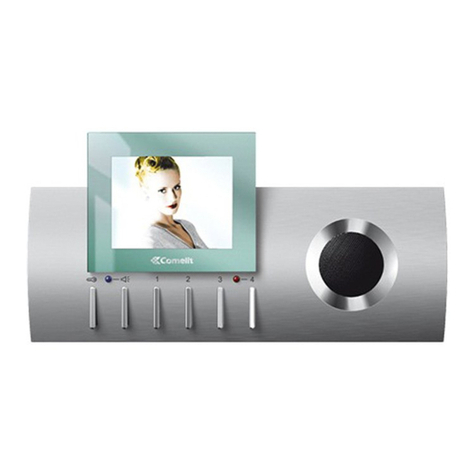
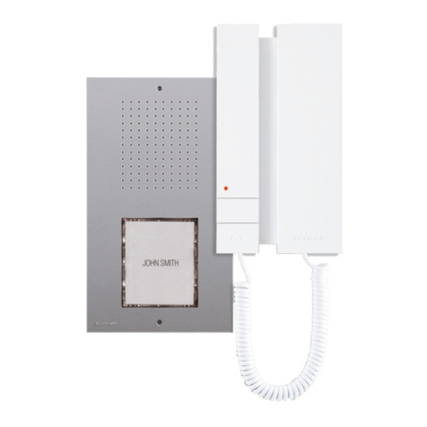
  9. Comelit HFX-9500M User manual

Comelit HFX-9500M User manual

Other manuals for HFX-9500M

1

Other Comelit Intercom System manuals

Comelit KCA2071 User manual

Comelit

Comelit KCA2071 User manual

Comelit Diva series Instruction Manual

Comelit

Comelit Diva series Instruction Manual

Comelit 6602W/BM User manual

Comelit

Comelit 6602W/BM User manual

Comelit HFX-7000M User manual

Comelit

Comelit HFX-7000M User manual

Comelit KAE5062A User manual

Comelit

Comelit KAE5062A User manual

Comelit Mini 6751W User manual

Comelit

Comelit Mini 6751W User manual

Comelit 6602W User manual

Comelit

Comelit 6602W User manual
Comelit Planux 8172IP User manual

Comelit

Comelit Planux 8172IP User manual

Comelit KCA2071A User manual

Comelit

Comelit KCA2071A User manual

Comelit 8171IGK User manual

Comelit

Comelit 8171IGK User manual

Comelit HFX-7000MW User manual

Comelit

Comelit HFX-7000MW User manual

Comelit Mini 6721W User manual

Comelit

Comelit Mini 6721W User manual

Comelit Venice User manual

Comelit

Comelit Venice User manual

Comelit IX0102KP User manual

Comelit

Comelit IX0102KP User manual

Comelit Mini 6701W/BM User manual

Comelit

Comelit Mini 6701W/BM User manual

Comelit HFX-700M User manual

Comelit

Comelit HFX-700M User manual

Comelit FT SB2 14 Instruction Manual

Comelit

Comelit FT SB2 14 Instruction Manual

Comelit Simplebus 2 FT SB2 15 Instruction Manual
Comelit

Comelit Simplebus 2 FT SB2 15 Instruction Manual

Comelit Genius Series Instruction Manual

Comelit

Comelit Genius Series Instruction Manual

Comelit 3451S User manual

Comelit

Comelit 3451S User manual

Comelit 8471S User manual

Comelit

Comelit 8471S User manual

Comelit Logicom User manual

Comelit

Comelit Logicom User manual

Comelit FT EASYCOM 01 User manual

Comelit

Comelit FT EASYCOM 01 User manual

Comelit 4893M User manual

Comelit

Comelit 4893M User manual

Popular Intercom System manuals by other brands

Videx VRDK1 (25H) Technical manual

Videx

Videx VRDK1 (25H) Technical manual

Auta COMPACT VISUALTECH manual

Auta

Auta COMPACT VISUALTECH manual

Aiphone LC-10S instructions

Aiphone

Aiphone LC-10S instructions

Aiphone PD-1 instructions

Aiphone

Aiphone PD-1 instructions

Aiphone JF-DVF-HID-I instructions

Aiphone

Aiphone JF-DVF-HID-I instructions

MGL Avionics V16 manual

MGL Avionics

MGL Avionics V16 manual

SSS Siedle BVI 750-0 Installation & programming

SSS Siedle

SSS Siedle BVI 750-0 Installation & programming

urmet domus AIKO 1716/1 quick start guide

urmet domus

urmet domus AIKO 1716/1 quick start guide

urmet domus IPerVoice 1039 Installation

urmet domus

urmet domus IPerVoice 1039 Installation

Alpha Communications STR QwikBus TT33-2 Installation, programming, and  user's manual

Alpha Communications

Alpha Communications STR QwikBus TT33-2 Installation, programming, and user's manual

Monacor ICM-20H instruction manual

Monacor

Monacor ICM-20H instruction manual

Logenex A202CR Installation & programming

Logenex

Logenex A202CR Installation & programming

Quantum QR5 Installation and programming manual

Quantum

Quantum QR5 Installation and programming manual

EVGA XR1 quick guide

EVGA

EVGA XR1 quick guide

CyberData 011211 series Installation quick reference

CyberData

CyberData 011211 series Installation quick reference

Vidos duo M1021 user manual

Vidos

Vidos duo M1021 user manual

Savant DOR-SMS-00 Deployment guide

Savant

Savant DOR-SMS-00 Deployment guide

SSS Siedle BTSV 850-03 operating instructions

SSS Siedle

SSS Siedle BTSV 850-03 operating instructions

manuals.online logo
manuals.online logoBrands
  • About & Mission
  • Contact us
  • Privacy Policy
  • Terms and Conditions

Copyright 2025 Manuals.Online. All Rights Reserved.

FREE DOWNLOAD
MYCOMELIT, L'APP PER IL PROFESSIONISTA
MYCOMELIT: THE APP FOR PROFESSIONALS
EN
QUICK
REFERENCE
GUIDE
EN FR ES
Single-User Kit HFX-9500M
also available in
French and Spanish
2
EX-9000H 1209/8EX-B
HFX-9500M Kit
tech sheet
×3 ×3
screws
dry wall
anchors
Nameplate
for 1 user
external unit
×1
YOUR NAME
EX-B - External unit
screwspower supply
×1 ×4
1209/8 - BUS Power supply
EX-9000H - Door entry monitor
Technical manual
screwsmonitor + terminal block
metal frame
support
screwsdry wall
anchors
monitor wall
support
×1 ×1 ×4 ×4
×4
×1
×1
×2
screws
×4
×4
clips for dry
lined walls tech sheet
×2
dry wall
anchors
dry wall
anchors
screws
screws
screws tech sheet
tech sheet
external unit
screwspower supply
door entry
monitor wall
support
metal frame
support
clips for dry
lined walls
monitor + terminal blocks screws
Nameplate
for 1 user
This QRG contains all the basic
informations to install the single-
user kit.
Additional features are available
in the full manual at the web site
pro.comelitgroup.com_HFX-9500M
_ MANUALS
1. Contents of the package
3
2. Parts identification
2.1 EX-B EXTERNAL UNIT
3.15 in
5.90 in
1.06
1.14
1.18 in
9.
11.
12.
13.
10.
14.
8.
1. 3.
4.
5.
6.
7.
2.
1.
1. Hole for wall mounting
2. Terminal block
L L bus line connection
RTE programmable RTE (local lock-release input) or
DO input (door open indication)
GND / SE- RTE and door lock input reference negative
SE+ electric door lock connection
NO relay normally open contact
Crelay common contact
3. Microphone
4. Wide-angle colour camera
5. Camera lighting LED
6. Nameplate
7. Call button
8. Adjustment trimmer (See page 16)
9. Addressing and programming DIP-switches
10. CNF Programming confirmation button
11. S2 Special programming selector
12. S1 Button programming selector
13. Loudspeaker
14. Fixing screw
4
0.98 in
4.88 in
8.77 in
1. 2.
8.7.6.5.4.3.
2.2 EX-9000H DOOR ENTRY MONITOR
1. 7” colour LCD screen
2. Microphone
Audio key / Paging call key
Lock-release key
Keys 1-2-3-4 (programmable)
Self activation key (programmable)
Silent mode (Privacy) key
Audio volume key
Ringtone volume key
Value 'Up/Down' key
Contrast key
Brightness key
3. S1 Micro-switches for user code setting
4. Terminal block for system connection:
LLBus line connection terminals
- + Power supply terminals
IN2 IN1 Input terminals (programmable)
S- S+ Terminals for additional ringtone output
CFP2 CFP1 Outside door call input
5. S2 Micro-switches for programming keys and functions
DIP 1-2-3-4 for key function programming
DIP 5-6 access to programming
DIP 7 unused
DIP 8: leave default setting (OFF)
6. CV6 see the full manual for more information
7. CV1 CV2 unused. Leave default setting (mounted)
8. CV5 Jumper for video closure
Indicator LED description
Audio key LED
steady = audio enabled/hands-free function
continuous flashing = call received
Lock-release LED
1 flash = confirm lock-release
4 flashes = programming successful
10 flashes = programming error
continuous flashing = call received/door open
Silent mode (Privacy) LED / Automatic lock-release
(Doctor mode) LED
4 flashes = device engaged
slow flashing = programming
3 flashes (every 5 s.) = Automatic lock-release enabled
steady = Silent mode enabled
5
3.
3.5
1. 2.
3.
4.
5.51 in 2.6 in
4.92 in
2.3 1209/8 BUS POWER SUPPLY
1. L1 | L1 door entry monitor connection 1
L2 | L2 door entry monitor connection 2
L3 | L3 door entry monitor connection 3
L4 | L4 door entry monitor connection 4
L5 | L5 door entry monitor connection 5
L6 | L6 door entry monitor connection 6
L7 | L7 door entry monitor connection 7
L8 | L8 door entry monitor connection 8
2. Video closing jumpers
REMOVE WHEN LINE IS USED
3. LP LP external unit connection
4. L N mains power input 110-240 V~
6
1. 2.
3.55 in
1.42 in 2.28 in
3. System installation
Wire Assignment Wire Assignment Wire Type Amax. Bmax. Cmax.
SINGLE PAIR CABLE CAT5
24AWG
557,74 feet
(170 m)
278,87 feet
(85 m)
278,87 feet
(85 m)
DOUBLE PAIR
CABLE
CAT5
24AWG
656,16 feet
(200 m)
328,08 feet
(100 m)
328,08 feet
(100 m)
MULTI PAIR CABLE
FOLLOW THE COLORS
SHOWN IN THE DIAGRAM!
GREEN
ORANGE
BLU
GREEN / WHITE
ORANGE / WHITE
BLU / WHITE
BROWN / WHITE
BROWN
CAT5
24AWG
1.115,48 feet
(340 m)
557,74 feet
(170 m)
557,74 feet
(170 m)
NON-BRAIDED
CABLE AWG22 787,40 feet
(240 m)
393,70 feet
(120 m)
393,70 feet
(120 m)
NON-BRAIDED
CABLE AWG18 787,40 feet
(240 m)
393,70 feet
(120 m)
393,70 feet
(120 m)
3.1 OPERATING DISTANCES AND SYSTEM LAYOUT
2.4 PARTS IDENTIFICATION FOR EXPANSION
ADDITIONAL INTERNAL UNIT
EX-9000H
EX-9000H
The art. EX-9000H is the additional internal unit for Single-User
Kits (see page 4for further information)
ADDITIONAL EXTERNAL UNIT
EX-BSB
+
1405
EX-B
The art. EX-BSB is the additional external unit for Single-User
Kits and contains the external unit art. EX-B (see page 3for
further information) and the Video door expander art. 1405 (see
point 2.4.1 for further information)
1. LM LM art. 1209/8 connection
2. LS | LS additional external unit connection
LP | LP main external unit connection
2.4.1 Art. 1405 Video door expander
NOTE: This system is capable to expanding up to 4 external units and 8 internal units. For alternative application please consult
our technical support engineer first.
At the first connection on the riser, the internal units automatically acquire theirs sub-addresses.
The LEDs and flash simultaneously for some seconds. After the procedure the LEDs will turn off.
7
A
B
C
1209/8
EX-9000H
expansion
door entry monitor
EX-9000H
expansion
door entry monitor
HFX-9500M
EX-9000H
EX-9000H
expansion
door entry monitor
EX-9000H
expansion
door entry monitor
EX-9000H
expansion
door entry monitor
EX-9000H
expansion
door entry monitor
EX-9000H
expansion
door entry monitor
EX-B
3.1.2 Maximum Expansion Monitors in Daisy Chain connection
3.1.1 Single-User Kit art. HFX-9500M
A
B
C
1209/8
HFX-9500M
EX-9000H
EX-B
expansion
door entry monitor
expansion
door entry monitor
expansion
door entry monitor
expansion
door entry monitor
expansion
door entry monitor
expansion
door entry monitor
expansion
door entry monitor
Maximum 2 door entry monitors per output
8
EX-BSB
+
1405EX-B
The art. EX-BSB is the additional external unit for Single-User Kits and contains the external unit art. EX-B and the Video door
expander art. 1405
1405 1405
1405
1209/8
A
B
C
HFX-9500M
EX-BSB
expansion external unit
EX-BSB
expansion external unit
EX-BSB
expansion external unit
EX-9000H
expansion
door entry monitor
EX-9000H
expansion
door entry monitor
EX-9000H
EX-9000H
expansion
door entry monitor
EX-9000H
expansion
door entry monitor
EX-9000H
expansion
door entry monitor
EX-9000H
expansion
door entry monitor
EX-9000H
expansion
door entry monitor
EX-B EX-B EX-B EX-B
3.1.3 Full System Expansion Diagram
expansion
door entry monitor
expansion external unit expansion external unit expansion external unit
expansion
door entry monitor
expansion
door entry monitor
expansion
door entry monitor
expansion
door entry monitor
expansion
door entry monitor
expansion
door entry monitor
9
Local lock release button
EX-9000H
S
+
S
-
C
F
P
L L
C
F
P
1
-
+
2
IN
1 2
IN
1209/8
L1 L1 L2 L2
LN
110-240V
LP LP L3 L3 L4 L4 L5 L5 L6 L6 L7 L7 L8 L8
LL
E
T
R
NO
GND
SE-
SE
+
C
EX-B
S1 A
LEAVE DEFAULT SETTING
ON
1 2 3 4 6 75 8
LEAVE DEFAULT SETTINGS
STANDARD INSTALLATION
Basic single-user kit
10
S1 A
LEAVE DEFAULT SETTING
ON
1 2 3 4 6 75 8
S1 A
LEAVE DEFAULT SETTING
ON
1 2 3 4 6 75 8
S1 A
LEAVE DEFAULT SETTING
ON
1 2 3 4 6 75 8
S1 A
LEAVE DEFAULT SETTING
ON
1 2 3 4 6 75 8
S1 A
LEAVE DEFAULT SETTING
ON
1 2 3 4 6 75 8
S1 A
LEAVE DEFAULT SETTING
ON
1 2 3 4 6 75 8
S1 A
LEAVE DEFAULT SETTING
ON
1 2 3 4 6 75 8
-
HFX-9500M
REMOVE WHEN LINE IS USED
REMOVE CV5 REMOVE CV5
EX-B
S
+
S
-
C
F
P
L L
C
F
P
1
-
+
2
IN
1 2
IN
1209/8
L1 L1 L2 L2
LN
110-240V
LP LP L3 L3 L4 L4 L5 L5 L6 L6 L7 L7 L8 L8
S
+
S
-
C
F
P
L L
C
F
P
1
-
+
2
IN
1 2
INS
+
S
C
F
P
L L
C
F
P
1
-
+
2
IN
1 2
IN
S
+
S
-
C
F
P
L L
C
F
P
1
-
+
2
IN
1 2
IN
S
+
S
-
C
F
P
L L
C
F
P
1
-
+
2
IN
1 2
IN
S
+
S
-
C
F
P
L L
C
F
P
1
-
+
2
IN
1 2
INS
+
S
-
C
F
P
L L
C
F
P
1
-
+
2
IN
1 2
IN
EX-9000H EX-9000H
EX-9000H EX-9000H
EX-9000H EX-9000H
EX-9000H EX-9000H
S
+
S
-
C
F
P
L L
C
F
P
1
-
+
2
IN
1 2
IN
S1 A
LEAVE DEFAULT SETTING
ON
1 2 3 4 6 75 8
CV5
Video Closing Jumper
LEAVE DEFAULT SETTINGS LEAVE DEFAULT SETTINGS
LEAVE DEFAULT SETTINGS
Video closing jumper
LEAVE DEFAULT SETTINGS
REMOVE CV5 REMOVE CV5
REMOVE CV5REMOVE CV5
MAXIMUM EXPANSION IN DAISY CHAIN CONNECTION
Expanded single-user kit
REMOVE WHEN LINE IS USED