9
Sicurezza
Installazione
Istruzioni di sicurezza
Assicurarsi che il personale incaricato di installare e opera-
re sull’isolatore passante:
• sia tecnicamente qualicato e competente.
• rispetti pedissequamente queste istruzioni
d’assemblaggio.
L’uso improprio di questi oggetti potrebbe determinare
pericolo per:
• vita e arti
• attrezzatura e altri beni dell’operatore
• corretto funzionamento dell’attrezzatura.
Le istruzioni di sicurezza di questo manuale sono riportate in
tre diversi formati per sottolineare informazioni importanti.
Note di sicurezza sul funzionamento dell’apparecchiatura
L’installazione elettrica è soggetta alle leggi nazionali di
sicurezza.
Questa informazione indica un particolare pericolo per la vita e
la salute. Ignorare questo tipo di avvertimento potrebbe causare
ferite gravi o fatali
Il regolamento antincendio deve essere rigorosamente rispettato.
Questa informazione indica un particolare pericolo per
l'attrezzatura o altri beni dell'operatore. Ferite gravi o fatali non
sono da escludersi.
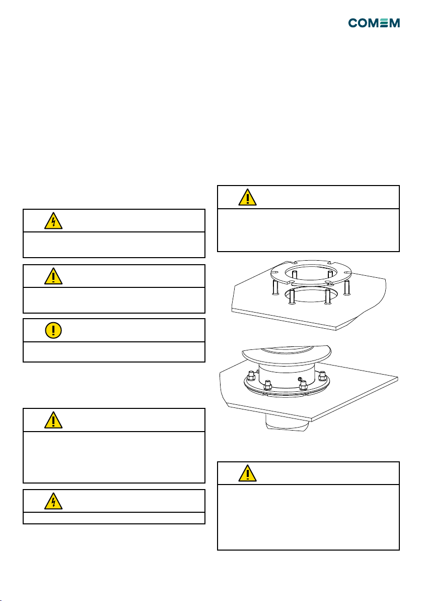
L'installazione, la connessione elettrica e il montaggio
dell'isolatore devono essere effettuati da personale qualificato e
solo secondo questo manuale di istruzioni.
E' responsabilità dell'utente assicurarsi che l'isolatore sia
utilizzato per la sua corretta applicazione.
Per questioni di sicurezza, evitare usi non autorizzati o impropri.
Questa nota offre informazioni importanti o specifiche
sull'attrezzatura o su come operarvi
AVVERTIMENTO
AVVERTIMENTO
ATTENZIONE
ATTENZIONE
Leggere attentamente questo manuale d'istruzioni prima di
mettere in esercizio l'isolatore.
La messa a terra deve essere assicurata tramite i cavi forniti a
corredo. La vite di terra non deve essere utilizzata a scopo di
monitoraggio.
ATTENZIONE
Le connessioni elettriche devono essere eseguite
esclusivamente da personale qualificato e formato secondo
le normative nazionali vigenti in materia di sicurezza e salute.
Particolare attenzione deve essere posta al fine di evitare
fenomeni di ionizzazione. Scegliere adeguatamente la sezione
del connettore da utilizzare e quindi collegarlo applicando una
coppia di serraggio come da tabella 1 (tale valore è in funzione
della corrente nominale del CRS).
ATTENZIONE
NOTA
Cablaggio
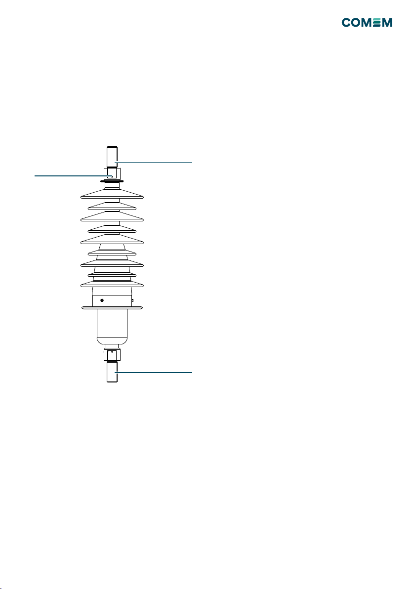
Descrizione del prodotto
Il CRS è un isolatore passante del tipo “non a condensato-
re”. Il CRS deve essere collegato a terra tramite le apposite
viti sopra la angia di ssaggio. Tali isolatori sono pro-
gettati per operare con la parte superiore in aria e la parte
inferiore in olio. Il CRS è stato progettato e prodotto in
conformità alla norma IEC 60137.
Figura 1
Figura 2
This document is issued by means of a computerized system.
The digitally stored original is electronically approved. The
approved document has a date entered in the `Approved'-field.
A manual signature is not required.
We reserve all rights in this document and in the information
contained therein. Reproduction, use or disclosure to third
parties without express authority is strictly fobidden.
F
E
D
C
B
8765432
A
1 109 11 12
G
H
1 2 3 4 5 6 7 8 9 10 11 12
A
B
C
D
E
F
G
H
DRAWING SHEET ISO 5457:1999-A2T
LAST REVISION
DESCRIPTION
MODIFICATO CODICE RIFERIMENTO SET - Changed P/N kit
REPLACED
REVISION
TOLLERANZE GENERALI SECONDO - GENERAL TOLERANCES ACCORDING TO ISO 2768
m
SCALE
NO
MATERIAL WEIGHT - kg
- - -
-
PROCESS PART NUMBER
- - 5COH046700
1/11
A
Development
NH-546
SHEETITERREVSTATUSDOCUMENT ID
ITABB-9AAE306693 ARCING HORN SET FOR CRS 52kV
RESPONSIBLE DEPARTMENT
ISTRUZIONI CRS
COMEM
TITLE / SUPPLEMENTARY TITLERESPONSIBLE COMPANY
Component Drawing-
PROJECT IDWORK ORDER IDBASED ON DOC IDDOCUMENT KINDAPPROVED ON
--Diego Boro
APPROVED BYREVIEWED BYCREATED BY
© COPYRIGHT ALL RIGHTS RESERVED