COMEM eSDB XS User manual

Self-dehydrating breathers
eSDB XS/S/M/L
EN-IT-DE-ES-FR
INSTRUCTION MANUAL

2
CONTENT INDEX
Content index
Safety ...........................................................4
Product description ......................................4
Installation....................................................6
Electrical connection....................................6
Technical data ..............................................7
Applications..................................................8
Operation and maintenance .........................9
Appendix A - Options..................................10
Appendix B
Overvoltage protection replacement
instruction ..................................................11
Appendix C - How to operate the menu......13
Appendix D - MODBUS communication......54
Appendix E - Drawings................................55
Indice dei contenuti
Sicurezza....................................................14
Descrizione del prodotto ............................14
Installazione ...............................................16
Connessioni elettriche................................16
Caratteristiche tecniche .............................17
Applicazioni................................................18
Funzionamento e manutenzione ................19
Appendice A - Opzioni ................................20
Appendice B
Istruzione per la sostituzione della
protezione da sovratensione .....................21
Appendice C - Funzionamento del menu....23
Appendice D - Comunicazione MODBUS....54
Appendice E - Disegni.................................55
Inhalt
Sicherheit ...................................................24
Produktbeschreibung .................................24
Installation..................................................26
Elektrischer Anschluss ...............................26
Technische Merkmale ................................27
Anwendungen.............................................28
Betrieb und Wartung...................................29
Anhang A - Optionen...................................30
Anhang B
Anleitung zum Auswechseln des
Überspannungsschutzes............................31
Anhang C - Menübedienung .......................33
Anhang D - MODBUS-Kommunikation........54
Anhang E - Zeichnungen.............................55
Índice de contenidos
Seguridad ...................................................34
DescripciÓn del producto............................34
InstalaciÓn..................................................36
ConexiÓn eléctrica......................................36
Carateristicas técnicas...............................37
Aplicaciones...............................................38
Funcionamento y mantenimiento...............39
Apéndice A - Opciones ...............................40
Apéndice B
Instrucciones de sustitución de la
protección contra sobretensiones .............41
Apéndice C - Uso de los menus..................43
Apéndice D - Comunicación MODBUS........54
Apéndice E - Dibujos ..................................55

3
Index du contenu
Securitè ......................................................44
Description du produit................................44
Installation..................................................46
Raccordement électrique ...........................46
Caractéristiques techniques.......................47
Applications................................................48
Utilisation et entretien ................................49
Annexe A - Options.....................................50
Annexe B
Instructions de remplacement de la
protection contre les surtensions...............51
Annexe C - Opération de menu...................53
Annexe D - Communication MODBUS ........54
Annexe E - Dessins .....................................55

4
Safety Product description
Safety instructions
Make sure that any person installing, taking into operation
and operating the self-dehydrating breather:
• is technically qualified and competent
• fully complies with these assembling instructions
Improper operations or misuse could cause danger to:
• life and limb
• the equipment and other assets of the operator
• the equipment proper function
Safety instructions in this manual are shown in three
different forms to emphasize important information.
Safety notes on the equipment operation
Electrical installation is subject to the relevant national
safety rules.
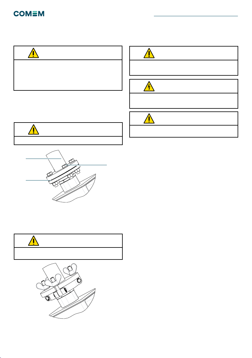
It is mandatory to connect the grounding cable to the
ground screw (Fig. 8-9).
This information indicates particular danger to life and health.
Disregarding such a warning can lead to serious or fatal injury.
It is important to observe the limit values indicated on
the nameplate and in the operating instruction before
commissioning the device.
All relevant fire protection regulation must be strictly observed.
This information indicates particular danger to equipment or
other property of the user. Serious or fatal injury cannot be
excluded.
Installation, electrical connection and fitting the device may only
be performed by qualified personnel and only in accordance
with this instruction manual. It is the responsibility of the user
to ensure that the device is used for specified application only.
For safety reasons, please avoid any unauthorized and improper
usage.
During the regeneration phase, the surface temperature
increases. Touching the surface is dangerous.
This notes give important or specific information concerning the
equipment or as to work with the equipment.
WARNING
WARNING
WARNING
CAUTION
CAUTION
CAUTION
NOTE
The dehydrating breather is used for oil-insulated tran-
sformer and on-load tap-changer to dry the air which is
suctioned in by the oil conservator during the thermal
contraction of the oil mass.
During the normal operation the oil conservator intakes
air that passes through the metallic filter (Fig. 8-9; intel/
outlet air). The metallic filter stops dust, sand and other
particles from the contaminating air. The air then passes
through the tank 1. The salt tank is filled with silica gel
that absorbs the moisture.
When the silica gel absorbs the moisture, the weight of the
salt and the relative humidity of air increase.
Monitoring of silica gel status is carried out by:
• Weight cell and Humidity sensor for eSDB M/L
• Humidity sensor for eSDB XS/S
When the weight and/or relative humidity increase and
exceed the pre-set value a regeneration process starts.
Two heating systems (inside tank 1 and 2) are alternately
activated; the solenoid valve is energized during the tank
1 regeneration.
The water vapor leaving the silica gel is expelled outward
by a fan that also dissipates the heat (eSDB M/L).
Inside the tank, a probe monitors the temperature of the
heating element.
No maintenance is required for replacement and
regeneration of the desiccant.
SELF-DEHYDRATING BREATHERS eSDB XS/S/M/L

5
Self-monitoring function
The self-dehydrating air breather has a self-monitoring
function.
Outputs
STANDARD CONFIGURATION SPECIAL CONFIGURATION
Malfunction What is detected Malfunction What is detected
POWER FAILURE - Failure of the power supply
- Failure of the electronic circuit
POWER FAILURE - Failure of the power supply
- Failure of the electronic circuit
- Failure of the heating element
- Failure of the weighing cell
- Failure of solenoid valve
SYSTEM FAILURE - Failure of the heating element
- Failure of the weighing cell
- Failure of solenoid valve
STANDARD CONFIGURATION SPECIAL CONFIGURATION
STANDARD RELAY 1 x change over contact: POWER FAILURE
(terminals 22-24-21)
1 x change over contact: SYSTEM FAILURE
(terminals 12-14-11)
1 x NC contact: POWER FAILURE
(terminals 22-21)
1 x change over contact: HEATER ON
(terminals 12-14-11)
USB type A Interface to download relevant device data Interface to download relevant device data
OPTIONS ANALOG OUTPUTS 2 x 4-20 mA (terminals 41-44 and 2-1)
(Minimum / Maximum resistance: 100 / 470 Ohm)
2 x 4-20 mA (terminals 41-44 and 2-1)
(Minimum / Maximum resistance: 100 / 470 Ohm)
DIGITAL OUTPUT:
Modbus RTU
RS485 (terminals 3-4) RS485 (terminals 3-4)
DIGITAL OUTPUT:
Modbus TCP/IP
Ethernet port Ethernet port
Table 1
Table 2
Table 3
When the device has got a failure, this is detected by
contacts that can be set in accordance to customer
demand on the following configuration:
Status indicators
N°9 ICONs which indicate the status of the device are
installed inside the terminal box and observable through
the glass.
Figura 1
Idle - Green
Warning - Yellow
(Fixed tank 1, Blinking tank 2)
Drying - Yellow
(Fixed tank 1, Blinking tank 2)
Cooling - Yellow
(Fixed tank 1, Blinking tank 2)
USB active - Blue
Electronic board failure - Red
Heater failure - Red
Solenoid valve failure - Red
Drying failure - Red
Sensors reading - White
Temperature Tank °C
Salt Saturation /
Humidity (1)
Terminal Board
Command Buttons
Modbus Address
Selection
USB Type A
Port
Ethernet
Port
Overvoltage protection
(1) Salt saturation for eSDB M/L; Relative Humidity for eSDB XS/S

6
Installation
The operating and installation requirements described in this
manual must be strictly followed. If not, the device can be
damaged or a malfunction may occur. The unit must be mounted
level and upright. The unit and piping must be installed so the
oil is not able to enter the breather. Do not install in an enclosed
cabinet; proper ventilation is required.
CAUTION
Figure 3
Put the plane gasket between the two anges.
The minimum thickness ange has to be 15 mm.
CAUTION
CAUTION
eSDB XS/S/M/L
EN Flange: Remove the tape/plastic cap from the upper
ange (Fig. 2/A). Fix the upper ange (Fig. 2/A) on the
ange of the pipe from the conservator (Fig. 2/B) with four
M12 screws (Fig. 2/C).
DIN Flange: Remove the tape/plastic cap from the upper
ange. The rotation range shall be completely covered
adjusting the position of eSDB and xing locknut.
Figure 2
B
A
C
SELF-DEHYDRATING BREATHERS eSDB XS/S/M/L
During the terminal box assembly, use caution not to damage
the OR gasket. If this occurs it must be substituted.
CAUTION
Electrical connection
To wire the dehydrating breather, open the terminal box
(Fig. 8-9). An external ground screw is positioned on the
upper part of device (Fig. 8-9).
Power voltage
First, connect protective ground externally.
Connect the power voltage (as written on the terminal box
cover) to terminals 31- 32.
Relay
Standard Configuration
There are 2 contact failures:
• 1 x change over contact: POWER FAILURE
(terminal 22-24-21)
- NO contact: terminals 24-21
- NC contact: terminals 21-22
After supply voltage:
- NC contact: terminals 24-21
- NO contact: terminals 21-22
• 1 x change over contact: SYSTEM FAILURE
(terminal 12-14-11)
- NO contact: terminals 14-11
- NC contact: terminals 11-12
Special Configuration:
There is one-contact failures:
• 1 x NC contact: POWER FAILURE (terminal 22-21)
- NC contact: terminals 21-22
After supply voltage:
- NO contact: terminals 21-22
• 1 x change over contact: HEATER ON
(terminal 12-14-11)
- NO contact: terminals 14-11
- NC contact: terminals 11-12
Electrical connections should only be performed by qualied
and skilled personnel trained in the applicable health and safety
regulations of the relevant country.
CAUTION
Dangerous electrical voltages!
It is imperative to deactivate the power supply during wiring of
the device.
WARNING

7
The alarm relays (contact failure) will not trip the transformer.
Close the free cable gland with a plug or gasket if the cable
glands are not used.
CAUTION
CAUTION
Technical data
Analog Outputs (optional)
4-20 mA – Output 1: terminals 41-44
4-20 mA – Output2: terminals 2-1
Type Power consumption (1) Silica gel (main tank) Weight
eSDB XS 320 W 1.5 kg / 3.3 lb 14 kg / 30.9 lb
eSDB S 320 W 1.5 kg / 3.3 lb 15 kg / 33.1 lb
eSDB M 640 W 2.5 kg / 5.5 lb 20 kg / 44.1 lb
eSDB L 640 W 3.0 kg / 6.6 lb 22.5 kg / 49.6 lb
Comem eSDB Technical data
Material All the external part are resistant to transformer oils, salt fog and UV rays –
Aluminum and stainless steel(1)
Four types of installation
environment
Indoor/Outdoor/Tropical proof
Offshore
Corrosion class: C5-Medium
Corrosion class: C5-High / CX
Grey
RAL 7035 (on request)
Standard IEC 60076-22-7
Ambient temperature From -40 °C to 80 °C (from -40 °F to 176 °F)
Degree of protection IP65 according to EN 60529
Degree of protection of terminal
box
IP66 according to EN 60529
Ventilation valve To prevent the formation of condensation
Desiccant Colorless, non-poisonous silicagel; amount according application table above
Cable glands 3 x M25x1.5
Functional test Standard
Overvoltage protection Standard (replaceable varistor and fuse)
Heating element protection Standard (replaceable fuse)
Redundancy Double feedback signal - Humidity sensor and load cell (for M & L types)
Display User-friendly – Quick access menu
Flange type DIN or EN ange
Digital Outputs (optional)
Digital output Modbus RTU (RS485): terminals 3-4.
Digital output Modbus TCP/IP: ethernet port
Power supply)
Rated Voltage From 115 to 230 V ac/dc ± 10% 50/60 Hz
Current consumption Max 100 mA (during normal operation)
Maximum current during regeneration < 3 A (during regeneration)
Heating element insulation 2.0 kV 50/60 Hz, 1 min
External protection Automatic circuit breaker 16 A – 20 A, characteristic: C – K – Z
Table 4
Table 5
Table 6

8
Applications
Table 7
For each application, in case of the quantity of oil exceed the max
value for each breather, we advise to put 2 eSDB in parallel.
NOTE
Signal contacts (1)
Braking capacity
(relays on the electronic card)
Voltage Current Braking
capacity
230V AC 2A 500 VA cosΦ>0,5
30/110/220V DC 0,83/0,23/0,11 A 500 VA L/R<40 ms
Dielectric strength of contacts Between contacts and ground: 2kV (60 sec)
Between contacts in open position: 1kV (60 sec)
Conguration Standard
1 x change over contact: POWER FAILURE
(terminals 22-24-21 – Relay 2)
1 x change over contact: SYSTEM FAILURE
(terminals 12-14-11 – Relay 1)
Special
1 x normally closed contact: POWER
FAILURE
(terminals 22-21 – Relay 2)
1 x change over contact: HEATER ON
(terminals 12-14-11 – Relay 1)
Outputs (1)
Analog outputs 2 x 4 – 20 mA (Max 30 m / 98 ft)
Output1: 4 mA = 0 % ... 20 mA = 100 %;
Output 2: 4 mA = -40 °C ... 20 mA = 155 °C
Digital outputs Modbus RTU – Serial port RS485 (Max 30 m / 98 ft)
Modbus TCP/IP – Ethernet port
Data logger – USB port
Recommended wires (1)
Power supply 14 AWG
Relay 18 AWG
4-20 mA 2 x 18 AWG (shielded twisted cable)
Modbus RTU 2 x 18 AWG (shielded twisted cable)
Modbus TCP/IP Category 5e straight cable
Technology Condition
Based
Condition
Based
Condition
Based
Condition
Based
eSDB type eSDB XS eSDB S eSDB M eSDB L
Application
Tap-changers - - -
Arc suppression coil (Petersen coil) - - -
Air-lled cable boxes - - -
Traction transformers - - -
Network transformers ≤ 40 MVA -- -
Network and generator step-up transformers > 40 MVA ≤ 200 MVA - - -
Generator and network intertie transformers > 200 MVA ---
Phase shifting transformers ≤ 40 MVA - - -
Phase shifting transformers > 40 MVA ≤ 200 MVA - - -
Phase shifting transformers > 200 MVA ---
Shunt reactors ≤ 40 Mvar - - -
Shunt reactors > 40 Mvar ≤ 200 Mvar - - -
Shunt reactors > 200 Mvar ---
HVDC transformers - - -
Furnace transformers - - -
Cavern transformers - - -
Quantity of oil ≤ 40t ≤ 40t > 40 ≤ 80t ≥ 80t
SELF-DEHYDRATING BREATHERS eSDB XS/S/M/L

9
It is not possible to do the functional test if the regeneration
process is activated.
If the fitting is not powered for more than 3 days, the clock will
re-start at the next powering from the date and hour of the end of
the last regeneration cycle.
NOTE
NOTE
Operation and
maintenance
Maintenance
During regular maintenance on the transformer, we
recommend
performing the following checks on the dehydrating
breather:
• Check the exterior condition of the device , especially the
metallic lter (Fig. 8-9; intel/outlet air)
• Check the failure contact
• Perform a functional test, follow instructions in
Appendix C.
Movement, transport and storage
Handle the device with care.
When you remove the device from the transformer (for
example during shipping operation), please follow the
procedure:
• Switch off the supply voltage
• Remove the supply wire from the terminal box
When you install the device please follow section from
page 6 to 8.The eSDB must be stored in the original packing
and in a dry place with temperature in the range -10÷40°C
(14÷104 °F).
Upon receiving the device, please check:
• The outer surface of the packaging to ensure that it is
intact
• That there are no breakages.
If damages are found, please contact COMEM and pro-
vide the information from the shipping list and the serial
number of the Self-dehydrating breather.
During the transformer transport, we advise to disassemble the
air breather and to place it inside the original box.
Not to paint the device. In this case any guarantees concerning
the corrosion resistance decline.
Only mild soap and water should be used to clean the electrical
box cover. Solvents must not be used for any reason as they
will degrade the performance. Use of solvents on the unit will
immediately void the warranty.
CAUTION
COMEM advices to disconnect eSDB during the electrical
transformer routine test.
NOTE
The total regeneration phase takes about 20 hours.
To abort the regeneration cycle, follow instructions in Appendix C.
CAUTION

10
Appendix A - Options
Flange DIN 45962 connection
The minimum thickness flange has to be 15 mm.
CAUTION
The rotation range shall be completely covered adjusting
the position of eSDB and xing the locknut.
Figure 4
Figure 5
Fault monitoring
The device has a self-monitoring function to detect inter-
nal faults, which are displayed by and failure contacts.
The following table lists the individual faults.
Fault
Indication
Error-relay
(Standard
conguration)
Error-relay
(Special
conguration)
Note
Failure of the
supply voltage All off POWER FAILURE:
terminal 22-24-21
POWER FAILURE:
terminal 22-24-21
Check if the supply voltage is connected correctly
Electronic control
defective Red - Fixed
POWER FAILURE:
terminal 22-24-21
POWER FAILURE:
terminal 22-24-21
Try to switch off and switch on the power supply. Reset the
device following instructions in Appendix C.
If the error remains, please contact us.
Heater 1
defective
Red - Fixed
SYSTEM FAILURE:
terminal 12-14-11
POWER FAILURE:
terminal 22-24-21
Reset the device following instructions in Appendix C.
If the error remains, please contact us.
Heater 2
defective
Red - Blinking
SYSTEM FAILURE:
terminal 12-14-11
POWER FAILURE:
terminal 22-24-21
Reset the device following instructions in Appendix C.
If the error remains, the dehydrating breather continues to work
because the main tank is not damage. In this condition, the
device may work for a long time. Please contact us to replace it.
WEIGHING CELL
defect/out of
range Red - Fixed
SYSTEM FAILURE:
terminal 12-14-11
POWER FAILURE:
terminal 22-24-21
Reset the device following instructions in Appendix C. If error
remains it means that the weighing cell is damaged. Control of
the weight is no longer available, but the device works because
of the sensors redundancy (Humidity sensor). If the error
remains, please contact us.
HUMIDITY
SENSOR
defect Red - Blinking
SYSTEM FAILURE:
terminal 12-14-11
POWER FAILURE:
terminal 22-24-21
Reset the device following instructions in Appendix C. If error
remains it means that the Humidity sensor is damaged. Control
of the humidity is no longer possible, but the device works
because of the sensors redundancy (Weight cell – eSDB M/L)
or the backup time control (eSDB XS/S). If the error remains the
dehydrating breather should be replaced. Please contact us.
EV Fail
defect Red - Fixed
SYSTEM FAILURE:
terminal 12-14-11
POWER FAILURE:
terminal 22-24-21
Reset the device following instructions in Appendix C. If error
remains it means that the solenoid valve is damaged, and the
dehydrating breather should be replaced. Please contact us.
Table 9
SELF-DEHYDRATING BREATHERS eSDB XS/S/M/L

11
Appendix B - Overvoltage protection replacement
instruction
Introduction
The scope of this instruction is to provide the instruction
for an easy and safe replacement or retrotting of the so
called "overvoltage protection" for eSDB.
Safety instruction
Make sure that the personnel installing/replacing the
"overvoltage protection"for eSDB:
• Are technically qualied and competent
• Fully comply with these assembling instructions
Improper operations or misuse could cause danger to:
• life and limb
• to the equipment and other assets of the operator
• to the proper function of the equipment.
Overvoltage protection replacement
Case
The overvoltage protection operated to protect the control
PCB so it has to be substituted by a new one.
Components
The kit to complete the replacement is made by the
following components (Tab.10):
Description Pictures
AVaristor:
It is provided by COMEM as spare part.
Each eSDB with overvoltage protection has
the rst varistor already mounted on the PCB
while an additional spare part is included in the
supply and placed within the electrical box.
BFuseS:
They are provided by COMEM as spare part.
Each eSDB with overvoltage protection has the
rst fuse already mounted on the PCB while an
additional spare part is included in the supply
and placed within the electrical box cover.
The second spare fuse, it is used for heater
element fuse replacement.
Table 10
Table 11
Main tools
The following tools have to be provided to the technician
who will take care of mentioned operations, COMEM will
not supply them.
Description Pictures
AScrewdriver
BKey n° 5 (for the screw type TCEI)
CTester

12
Operations
Table 12
Action description Tool Pictures/Notes
1Inform COMEM about the
switching of the eSDB due
to a suspect overvoltage.
0039 0444 449311
2Disconnect the supply
voltage
3Remove the electronic box
cover unscrewing the 4
screws
B
4Check with a tester on the
terminal 31-32 and verify
the absence of tension.
D
5Locate the overvoltage
protection position on
the bottom left of the
electronic control board.
Look for the varistor and
the fuse.
6Remove the Varistor
screwing the 2 screws on
the terminals and then slip
off the varistor.
A
7Remove the fuse with its
plastic protection
Action description Tool Pictures/Notes
8Insert the pin of the new
varistor in the terminal then
fasten the 2 screws on the
terminal.
A
9Mount a new Fuse in its
plastic protection.
10 Mount the Fuse on the
board with its plastic
protection.
C
11 Close the electrical box B
12 Powering the device
The varistor has to be
assembled in the same
position of the before one
bending the pins in order to
guarantee a right position, far
from the other components.
WARNING
SELF-DEHYDRATING BREATHERS eSDB XS/S/M/L

13
Appendix C - How to operate the menu
The board is equipped with three command buttons OK –
UP - DOWN (Fig. 6).
Main operations:
To START a regeneration cycle:
• Press for 5 seconds UP and DOWN at the same time.
“CMD” will appear.
• Press 1 time OK. “STR” will appear (rst line).
• Press 1 time OK. “ok” will appear (second line).
• After 30 seconds board exits automatically from user
menu
To ABORT a regeneration:
• Press for 5 seconds UP and DOWN at the same time.
“CMD” will appear.
• Press 1 time OK. “STR” will appear (rst line).
• Press 1 time UP. “ABR” will appear (rst line).
• Press 1 time OK. “ok” will appear (second line).
• After 30 seconds board exits automatically from user
menu.
To TEST the functionalities of LEDs and Relay :
• Press for 5 seconds UP and DOWN at the same time.
“CMD” will appear.
• Press 1 time OK. “STR” will appear (rst line).
• Press 2 time UP. “TST” will appear (rst line).
• Press 1 time OK. “ok” will appear (second line).
• After 30 seconds board exits automatically from user
menu.
Figure 6
To RESET the board:
• Press for 5 seconds UP and DOWN at the same time.
“CMD” will appear.
• Press 1 time OK. “STR” will appear (rst line).
• Press 4 time UP. “RES” will appear (rst line).
• Press 1 time OK. “ok” will appear (second line).
• After 30 seconds board exits automatically from user
menu.
To DOWNLOAD the data via USB Type B key:
• Insert USB Key
• Icon turns on (Blue)
• Press for 5 seconds UP and DOWN at the same time.
“CMD” will appear.
• Press 4 time UP. “DOL” will appear (rst line).
• Press 1 time OK. “ok” will appear (second line).
• After 30 seconds board exits automatically from user
menu.
OK
UP
DOWN First Line
Second Line

14
Sicurezza Descrizione del prodotto
Istruzioni di sicurezza
Accertarsi che qualsiasi soggetto che installi, metta in
funzione l’essiccatore autogenerante e operi su di esso:
• sia tecnicamente qualificato e competente
• rispetti pienamente le presenti istruzioni di
assemblaggio
Eventuali operazioni inadeguate o un utilizzo improprio
potrebbero costituire un pericolo per:
• vita e arti
• l'attrezzatura e altri beni dell’operatore
• il corretto funzionamento dell'attrezzatura
Le istruzioni di sicurezza contenute nel presente manuale
sono riportate in tre forme diverse per mettere in evidenza
le informazioni importanti.
Note di sicurezza sul funzionamento dell'apparecchiatura
L’installazione elettrica è soggetta alle norme nazionali
vigenti in materia di sicurezza.
È obbligatorio collegare il cavo di terra al morsetto di terra
(Fig. 8-9).
Questa informazione indica un particolare pericolo per la vita
e la salute. Il mancato rispetto di questo avvertimento può
causare lesioni gravi o mortali.
Prima della messa in servizio del dispositivo, è importante
rispettare i valori limite indicati sulla targhetta di identificazione
e nelle istruzioni operative.
È necessario rispettare rigorosamente tutte le normative in
vigore sulla protezione antincendio.
Questa informazione indica un particolare pericolo per
l’attrezzatura o altri beni dell’utente. Non è possibile escludere
lesioni gravi o mortali.
L’installazione, la connessione elettrica e il montaggio del
dispositivo possono essere eseguiti esclusivamente da
personale qualificato e solo in conformità con il presente
manuale di istruzioni. Rientra nella responsabilità dell’utente
garantire che il dispositivo sia utilizzato esclusivamente per
l’applicazione specificata. Per ragioni di sicurezza, evitare
qualsiasi uso non autorizzato e improprio.
Durante la fase di rigenerazione, la temperatura della superficie
aumenta. È pericoloso toccare la superficie.
Questa nota fornisce informazioni importanti o specifiche
relative all’apparecchiatura o sul modo su cui operarvi.
AVVERTIMENTO
AVVERTIMENTO
AVVERTIMENTO
ATTENZIONE
ATTENZIONE
ATTENZIONE
NOTA
L’essiccatore rigenerante è utilizzato per il trasformatore
isolato in olio e il commutatore sotto carico, per essiccare
l’aria aspirata in ingresso tramite il conservatore dell’olio,
durante la contrazione termica della massa di olio.
Nel corso del normale funzionamento, il conservatore
dell’olio assorbe l’aria che passa attraverso il filtro
metallico (Fig. 8-9; aria ingresso/uscita). Il filtro metallico
blocca polvere, sabbia e altre particelle contenute nell’aria.
L’aria poi passa attraverso il serbatoio 1. Il serbatoio viene
riempito con gel di silice che assorbe l’umidità.
Quando il gel di silice assorbe l’umidità, il peso del sale e
l’umidità relativa dell’aria aumenta.
Il monitoraggio dello stato del gel di silice viene eseguito
tramite:
• sensore di umidità e cella di carico per eSDB M/L
• sensore di umidità per eSDB XS/S
Quando il peso e/o l’umidità relativa aumentano e
superano il valore preimpostato, viene avviato un processo
di rigenerazione. Vengono attivati alternativamente due
sistemi di riscaldamento (all’interno del serbatoio 1 e del
serbatoio 2); l’elettrovalvola viene messa sotto tensione
durante la rigenerazione del serbatoio 1.
Il vapore acqueo che evapora dal gel di silice viene
espulso verso l’esterno tramite una ventola che dissipa
anche il calore (eSDB M/L).
All’interno del serbatoio, la temperatura dell’elemento
riscaldante viene monitorata da una sonda.
Non è richiesta manutenzione per la sostituzione e la
rigenerazione dell’essiccante.
ESSICCATORI AUTORIGENERANTI eSDB XS/S/M/L

15
Funzione di auto-monitoraggio
L’essiccatore autorigenerante dispone di una funzione di
auto-monitoraggio.
Uscite
CONFIGURAZIONE STANDARD CONFIGURAZIONE SPECIALE
Guasto Cosa viene rilevato Guasto Cosa viene rilevato
INTERRUZIONE DI
ALIMENTAZIONE
- Interruzione dell’alimentazione elettrica
- Guasto del circuito elettronico
INTERRUZIONE DI
ALIMENTAZIONE
- Interruzione dell’alimentazione elettrica
- Guasto del circuito elettronico
- Guasto dell’elemento riscaldante
- Guasto della cella di carico
- Guasto dell’elettrovalvola
GUASTO DEL SISTEMA - Guasto dell’elemento riscaldante
- Guasto della cella di carico
- Guasto dell’elettrovalvola
CONFIGURAZIONE STANDARD CONFIGURAZIONE SPECIALE
RELÈ
STANDARD
1 x contatto di scambio: INTERRUZIONE
ALIMENTAZIONE (terminali 22-24-21)
1 x contatto di scambio: GUASTO DEL SISTEMA
(terminali 12-14-11)
1 x contatto NC: INTERRUZIONE ALIMENTAZIONE
(terminali 22-21)
1 x contatto di scambio: RISCALDATORE ACCESO
(terminali 12-14-11)
USB tipo A Interfaccia per scaricare i dati specici del
dispositivo
Interfaccia per scaricare i dati specici del
dispositivo
OPZIONI USCITE ANALOGICHE 2 x 4-20 mA (terminali 41-44 e 2-1)
(Resistenza minima/massima: 100 / 470 Ohm)
2 x 4-20 mA (terminali 41-44 e 2-1)
(Resistenza minima/massima: 100 / 470 Ohm)
USCITA DIGITALE
Modbus RTU
RS485 (terminali 3-4) RS485 (terminali 3-4)
USCITA DIGITALE
Modbus TCP/IP
Porta Ethernet Porta Ethernet
Tabella 1
Tabella 2
Tabella 3
Quando il dispositivo presenta un guasto, quest’ultimo
viene rilevato tramite contatti che possono essere
configurati in base alla richiesta del cliente, alla seguente
configurazione:
Indicatori di stato
Le N°9 ICONE, che indicano lo stato del dispositivo, sono
installate all’interno della scatola elettrica e possono
essere osservate attraverso il vetro di ispezione.
Figura 1
Idle - Verde
Avvertenza - Giallo
(Serbatoio 1 sso, Serbatoio 2 lampeggiante)
Essiccazione - Giallo
(Serbatoio 1 sso, Serbatoio 2 lampeggiante)
Raffreddamento - Giallo
(Serbatoio 1 sso, Serbatoio 2 lampeggiante)
USB attiva - Blu
Guasto scheda elettronica - Rosso
Guasto riscaldatore - Rosso
Guasto elettrovalvola - Rosso
Guasto essiccazione - Rosso
Lettura sensori - Bianco
Temperatura °C serbatoio
Saturazione sali /
Umidità (1)
Morsettiera
Pulsanti di comando
Selezione indirizzi
Modbus
Porta USB
Tipo A
Porta
Ethernet
Protezione da sovratensione
(1) Saturazione sali eSDB M/L; umidità relativa per eSDB XS/S

16
Installazione
È necessario rispettare rigorosamente i requisiti operativi e di
installazione, descritti nel presente manuale. In caso contrario,
il dispositivo potrebbe subire danni o un guasto. L’unità deve
essere montata dritta e in verticale. L’unità e la tubazione
devono essere installate in modo tale che l’olio non possa
entrare nell’essiccatore. Non installare in un armadio chiuso;
l’unità deve disporre di una ventilazione adeguata.
ATTENZIONE
Figura 3
Posizionare la guarnizione piana tra le due ange.
Lo spessore minimo della angia deve essere 15 mm.
ATTENZIONE
ATTENZIONE
eSDB XS/S/M/L
Flangia EN: rimuovere il nastro/cappuccio in plastica dalla
angia superiore (Fig. 2/A). Fissare la angia superiore
(Fig. 2/A) sulla angia del tubo dal conservatore (Fig. 2/B)
con quattro viti M12 (Fig. 2/C).
Flangia DIN: rimuovere il nastro/cappuccio in plastica
dalla angia superiore. L’intervallo di rotazione dovrà
essere completamente coperto regolando la posizione di
eSDB e ssando il controdado.
Figura 2
B
A
C
ESSICCATORI AUTORIGENERANTI eSDB XS/S/M/L
Durante il montaggio della scatola elettrica, usare estrema
cautela per non danneggiare la guarnizione O-ring. In caso di
danno, deve essere sostituita.
ATTENZIONE
Collegamento elettrico
Per cablare l’essiccatore rigenerante, aprire la scatola
elettrica (Fig. 8-9). Un morsetto di terra esterno è
posizionato sulla parte superiore del dispositivo (Fig. 8-9).
Tensione di alimentazione
Prima di tutto, eseguire il collegamento della messa a
terra esterna.
Collegare la tensione di alimentazione (come riportato sul
coperchio della scatola elettrica) ai terminali 31- 32.
Relè
Configurazione standard
Sono presenti 2 contatti di segnalazione guasto:
• 1 x contatto di scambio: INTERRUZIONE
ALIMENTAZIONE (terminali 22-24-21)
- Contatto NO: terminali 24-21
- Contatto NC: terminali 21-22
Dopo l’accensione:
- Contatto NC: terminali 24-21
- Contatto NO: terminali 21-22
• 1 x contatto di scambio: GUASTO DEL SISTEMA
(terminali 12-14-11)
- Contatto NO: terminali 14-11
- Contatto NC: terminali 11-12
Configurazione speciale:
È presente un singolo contatto di segnalazione guasto:
• 1 x contatto NC: INTERRUZIONE ALIMENTAZIONE
(terminali 22-21)
- Contatto NC: terminali 21-22
Dopo l’accensione:
- Contatto NO: terminali 21-22
• 1 x contatto di scambio: RISCALDATORE ACCESO
(terminali 12-14-11)
- Contatto NO: terminali 14-11
- Contatto NC: terminali 11-12
I collegamenti elettrici devono essere eseguiti esclusivamente
da personale addestrato e qualicato, formato secondo le
normative vigenti in materia di salute e sicurezza del paese
interessato.
ATTENZIONE
Tensioni elettriche pericolose!
È obbligatorio disattivare l’alimentazione durante il cablaggio
del dispositivo.
AVVERTIMENTO

17
I relè allarme (mancanza contatto) non sono utilizzati per far
scattare il trasformatore.
Se i pressacavi non vengono utilizzati, chiudere il pressacavo
aperto con un tappo o la relativa guarnizione.
ATTENZIONE
ATTENZIONE
Dati tecnici
Uscite analogiche (opzionale)
4-20 mA – Uscita 1: terminali 41-44
4-20 mA – Uscita 2: terminali 2-1
Tipo Assorbimento (1) Gel di silice (serbatoio principale) Peso
eSDB XS 320 W 1,5 kg / 3,3 lb 14 kg / 30,9 lb
eSDB S 320 W 1,5 kg / 3,3 lb 15 kg / 33,1 lb
eSDB M 640 W 2,5 kg / 5,5 lb 20 kg / 44,1 lb
eSDB L 640 W 3,0 kg / 6,6 lb 22,5 kg / 49,6 lb
Comem eSDB Dati tecnici
Materiale Tutte le parti esterne sono resistenti all’olio del trasformatore, alla nebbia salina e ai raggi UV – Alluminio
e acciaio inossidabile(1)
Quattro tipi di ambiente di
installazione
Interni/Esterni/Tropicale
Offshore
Classe corrosione: C5-Media
Classe corrosione: C5-Alta / CX
Grigio
RAL 7035 (su richiesta)
Standard IEC 60076-22-7
Temperatura ambiente Da -40 °C a 80 °C (da -40 °F a 176 °F)
Grado di protezione IP65 in conformità a EN 60529
Grado di protezione della scatola
elettrica
IP66 in conformità a EN 60529
Valvola di ventilazione Per prevenire la formazione di condensa
Essiccante Incolore, gel di silice non tossico; quantità conforme alla precedente tabella di applicazione
Pressacavi 3 x M25x1,5
Test funzionale Standard
Protezione da sovratensione Standard (fusibile e varistore sostituibili)
Protezione elemento riscaldante Standard (fusibile sostituibile)
Ridondanza Segnale feedback doppio - Sensore umidità e cella di carico (per tipi M e L)
Display Facile da utilizzare – Menu ad accesso rapido
Tipo di angia Flangia DIN o EN
Uscite digitali (opzionale)
Uscita digitale Modbus RTU (RS485): terminali 3-4.
Uscita digitale Modbus TCP/IP: porta ethernet
Alimentazione)
Tensione nominale Da 115 a 230 V ca/cc ± 10% 50/60 Hz
Corrente assorbita Max 100 mA (durante il normale funzionamento)
Corrente massima durante la rigenerazione < 3 A (durante la rigenerazione)
Isolamento elementi riscaldanti 2,0 kV 50/60 Hz, 1 min
Protezione esterna Interruttore automatico 16 A – 20 A, caratteristica: C – K – Z
Tabella 4
Tabella 5
Tabella 6

18
Applicazioni
Tabella 7
Per ciascuna applicazione, in caso di quantità di olio che supera
il valore massimo per ciascun essiccatore, consigliamo di
posizionare 2 eSDB in parallelo.
NOTA
Contatti segnale (1)
Potere di interruzione
(relè su scheda elettronica)
Tensione Corrente Potere di interruzione
230V CA 2A 500 VA cosΦ>0,5
30/110/220V CC 0,83/0,23/0,11 A 500 VA L/R<40 ms
Tenuta dielettrica dei contatti Tra contatti e terra: 2kV (60 sec)
Tra contatti aperti: 1kV (60 sec)
Congurazione Standard
1 x contatto di scambio:
INTERRUZIONE ALIMENTAZIONE
(terminali 22-24-21 – Relè 2)
1 x contatto di scambio: GUASTO DEL
SISTEMA (terminali 12-14-11 – Relè 1)
Speciale
1 x contatto normalmente chiuso:
INTERRUZIONE ALIMENTAZIONE
(terminali 22-21– Relè 2)
1 x contatto di scambio: RISCALDATORE
ACCESO (terminali 12-14-11 – Relè 1)
Uscite (1)
Uscite analogiche 2 x 4 – 20 mA (Max 30 m / 98 ft)
Uscita 1: 4 mA = 0 % ... 20 mA = 100 %;
Uscita 2: 4 mA = -40 °C ... 20 mA = 155 °C
Uscite digitali Modbus RTU – Porta seriale RS485 (Max 30 m / 98 ft)
Modbus TCP/IP – Porta Ethernet
Registratore di dati – Porta USB
Cavi raccomandati (1)
Alimentazione 14 AWG
Relè 18 AWG
4-20 mA 2 x 18 AWG (cavo intrecciato schermato)
Modbus RTU 2 x 18 AWG (cavo intrecciato schermato)
Modbus TCP/IP Cavo dritto categoria 5e
Tecnologia Basata sulla
condizione
Basata sulla
condizione
Basata sulla
condizione
Basata sulla
condizione
Tipo eSDB eSDB XS eSDB S eSDB M eSDB L
Applicazione
Commutatori sotto carico - - -
Bobina di soppressione d’arco (bobina Petersen) - - -
Scatole di derivazione aria - - -
Trasformatori di trazione - - -
Trasformatori di rete ≤ 40 MVA -- -
Trasformatori elevatori di tensione generatore e rete > 40 MVA ≤
200 MVA - - -
Trasformatori inerzia generatore e rete > 200 MVA ---
Trasformatori sfasamento ≤ 40 MVA - - -
Trasformatori sfasamento > 40 MVA ≤ 200 MVA - - -
Trasformatori sfasamento > 200 MVA ---
Reattori in parallelo ≤ 40 Mvar - - -
Reattori in parallelo > 40 Mvar ≤ 200 Mvar - - -
Reattori in parallelo > 200 Mvar ---
Trasformatori HVDC - - -
Trasformatori forno - - -
Trasformatori caverna - - -
Quantità di olio ≤ 40t ≤ 40t > 40 ≤ 80t ≥ 80t
ESSICCATORI AUTORIGENERANTI eSDB XS/S/M/L

19
Non è possibile eseguire il test funzionale se il processo di
rigenerazione è in corso.
Se l’installazione non viene alimentata per più di 3 giorni,
l'orologio si riavvia all'alimentazione successiva, a partire dalla
data e dall’ora di fine ultimo ciclo di rigenerazione.
NOTA
NOTA
Funzionamento e
manutenzione
Manutenzione
Nel corso della manutenzione ordinaria sul trasformatore,
raccomandiamo
di eseguire i seguenti controlli sull’essiccatore
rigenerante:
• controllare la condizione esterna del dispositivo, in
particolare il ltro metallico (Fig. 8-9; aria ingresso/
uscita)
• controllare il contatto di segnalazione guasto
• eseguire una prova funzionale. Attenersi alle istruzioni
contenute nell’Allegato C.
Movimento, trasporto e conservazione
Maneggiare il dispositivo con cautela.
Quando il dispositivo viene rimosso dal trasformatore (ad
esempio, durante l’operazione di spedizione), attenersi alla
seguente procedura:
• spegnere l’alimentazione
• rimuovere il cavo di alimentazione dalla scatola elettrica
Per l’installazione del dispositivo, attenersi alla sezione
da pagina 6 a 8. L’eSDB deve essere conservato nella
confezione originale e in un luogo asciutto, a un intervallo
di temperatura di -10÷40°C (14÷104 °F).
Alla ricezione del dispositivo, controllare:
• la supercie esterna della confezione per accertarsi che
sia intatta
• l’assenza di rotture.
In presenza di danni, contattare COMEM e fornire le
informazioni contenute nella distinta della merce spedita e
il numero di serie dell’essiccatore autorigenerante.
Durante il trasporto del trasformatore, consigliamo di smontare
l’essiccatore e di collocarlo all’interno della confezione
originale.
Non verniciare il dispositivo. In tal caso, qualsiasi garanzia
relativa alla resistenza alla corrosione decade.
Per pulire il coperchio della scatola elettrica è possibile
utilizzare esclusivamente acqua e un sapone delicato. I solventi
non possono essere utilizzati per nessuna ragione in quanto
ne ridurrebbero le prestazioni. L’utilizzo di solventi sull’unità
invaliderà immediatamente la garanzia.
ATTENZIONE
COMEM consiglia di scollegare l’eSDB durante il test periodico
del trasformatore elettrico.
NOTA
Il ciclo totale di rigenerazione dura circa 20 ore.
Per interrompere il ciclo di rigenerazione, attenersi alle
istruzioni contenute nell’Allegato C.
ATTENZIONE

20
Allegato A - Opzioni
Collegamento angia DIN 45962
Lo spessore minimo della flangia deve essere 15 mm.
ATTENZIONE
L’intervallo di rotazione dovrà essere completamente
coperto regolando la posizione di eSDB e ssando il
controdado.
Figura 4
Figura 5
Monitoraggio guasti
Il dispositivo dispone di una funzione di automonitoraggio
per il rilevamento di guasti interni, che vengono segnalati
con e contatti di segnalazione guasto. La tabella che
segue elenca i singoli guasti.
Guasto
Indicazione
Errore relè
(congurazione
standard)
Errore relè
(congurazione
speciale)
Nota
Guasto
sull’alimentazione Tutti i
spenti
INTERRUZIONE
ALIMENTAZIONE:
terminali 22-24-21
INTERRUZIONE
ALIMENTAZIONE:
terminali 22-24-21
Vericare se la tensione di alimentazione è collegata
correttamente
Controllo
elettronico
difettoso Rosso -
Fisso
INTERRUZIONE
ALIMENTAZIONE:
terminali 22-24-21
INTERRUZIONE
ALIMENTAZIONE:
terminali 22-24-21
Cercare di spegnere e riaccendere l’alimentazione. Resettare il
dispositivo attenendosi alle istruzioni contenute nell’Allegato C.
Se l’errore persiste, contattarci.
Riscaldatore 1
difettoso
Rosso -
Fisso
GUASTO DEL
SISTEMA: terminali
12-14-11
INTERRUZIONE
ALIMENTAZIONE:
terminali 22-24-21
Resettare il dispositivo attenendosi alle istruzioni contenute
nell’Allegato C.
Se l’errore persiste, contattarci.
Riscaldatore 2
difettoso
Rosso -
Lampeg-
giante
GUASTO DEL
SISTEMA: terminali
12-14-11
INTERRUZIONE
ALIMENTAZIONE:
terminali 22-24-21
Resettare il dispositivo attenendosi alle istruzioni contenute
nell’Allegato C.
Se l’errore persiste, l’essiccatore rigenerante continua a
funzionare perché il serbatoio principale non è danneggiato. In
questa condizione, il dispositivo può funzionare per un lungo
periodo. Contattarci per sostituirlo.
CELLA DI CARICO
difettosa/fuori
range Rosso -
Fisso
GUASTO DEL
SISTEMA: terminali
12-14-11
INTERRUZIONE
ALIMENTAZIONE:
terminali 22-24-21
Resettare il dispositivo attenendosi alle istruzioni contenute
nell’Allegato C. Se l’errore persiste, la cella di carico è
danneggiata. Il controllo del peso non è più disponibile, ma il
dispositivo funziona per la ridondanza dei sensori (sensore
umidità). Se l’errore persiste, contattarci.
Difetto SENSORE
UMIDITÀ Rosso -
Lampeg-
giante
GUASTO DEL
SISTEMA: terminali
12-14-11
INTERRUZIONE
ALIMENTAZIONE:
terminali 22-24-21
Resettare il dispositivo attenendosi alle istruzioni contenute
nell’Allegato C. Se l’errore persiste, il Sensore umidità è
danneggiato. Il controllo dell’umidità non è più disponibile, ma
il dispositivo funziona per la ridondanza dei sensori (Cella di
carico – eSDB M/L) o il controllo del tempo di backup (eSDB
XS/S). Se l’errore persiste, è necessario sostituire l’essiccatore
rigenerante. Contattarci.
Guasto EV
UMIDITÀ Rosso -
Fisso
GUASTO DEL
SISTEMA: terminali
12-14-11
INTERRUZIONE
ALIMENTAZIONE:
terminali 22-24-21
Resettare il dispositivo attenendosi alle istruzioni contenute
nell’Allegato C. Se l’errore persiste, l’elettrovalvola è danneggiata
ed è necessario sostituire l’essiccatore rigenerante. Contattarci.
Tabella 9
ESSICCATORI AUTORIGENERANTI eSDB XS/S/M/L
This manual suits for next models
3
Table of contents
Languages:
Other COMEM Industrial Equipment manuals