COMEM RIS2 User manual

Integrated safety devices RIS2
EN-IT-DE-ES-FR
INSTRUCTION MANUAL

2
CONTENT INDEX
Content index
Safety ...........................................................4
Product description ......................................4
Installation....................................................4
Electrical connection....................................7
Technical features........................................8
Appendix A Drawings ................................ 29
Indice dei contenuti
Sicurezza......................................................9
Descrizione del prodotto ..............................9
Installazione .................................................9
Connessioni elettriche............................... 12
Caratteristiche tecniche ............................ 13
Appendice A Disegni ...................................29
Inhalt
Sicherheit ...................................................14
Produktbeschreibung ................................ 14
Installation................................................. 14
Elektrischer Anschluss .............................. 17
Technische Merkmale ............................... 18
Anlage A Zeichnungen............................... 29
Índice de contenidos
Seguridad ...................................................19
Descripción del producto........................... 19
Instalación................................................. 19
Conexión eléctrica..................................... 22
Características técnicas............................ 23
Apéndice A Planos .................................... 29

3
Index du contenu
Sécurité ......................................................24
Description du produit............................... 24
Installation................................................. 24
Raccordement électrique .......................... 27
Caractéristiques techniques...................... 28
Annexe A Dessins...................................... 29

4
Safety Product description
Installation
Safety instructions
Make sure that any person installing, taking into operation
and operating the safety detector:
• Is technically qualied and competent.
• Fully comply with these assembling instructions.
Improper operations or misuse could cause danger to:
• life and limb
• the equipment and other assets of the operator
• the equipment proper function
Safety instructions in this manual are shown in three diffe-
rent forms to emphasize important information.
Safety notes on the equipment operation
Electrical installation is subject to the relevant national
safety rules.
It is mandatory to connect the grounding cable because of
safety reason.
This information indicates particular danger to life and health.
Disregarding such a warning can lead to serious or fatal injury.
It is important to observe the limit values indicated on the
nameplate and in the manual before commissioning the device.
All relevant fire protection regulation must be strictly observed.
This information indicates particular danger to equipment and/
or other property of the user. Serious or fatal injury cannot be
excluded.
Installation, electrical connection and fitting the device have to
be carried out by qualified personnel and only in accordance to
this instruction manual.
It is responsibility of the user to make sure that the device is
used for specified application only.
For safety matters, please avoid any unauthorized and
improperly works.
This notes give important or specific information concerning the
equipment.
WARNING
WARNING
WARNING
CAUTION
CAUTION
NOTE
The RIS2 integrated safety detector is composed by a
rugged plastic body, watertight and resistant to extreme
climates, with a series of instruments which keep con-
stant control of the following operating conditions of the
transformer:
• Pressure
• Pressure switch: closes/opens a circuit on pressure
ranging (from 100 up to 500 mbar).
• Temperature
• Thermometer: visual indication of oil temperature and
max. temperature reached.
• “T2” Thermostat switch: (alarm) closes/opens a circuit
at a predetermined temperature level (from 30°C up to
120°C).
• “T1” Thermostat switch: (stop) closes/opens a circuit
at a predetermined temperature level (from 30°C up to
120°C).
• Oil level
• Indicator: visual indicator of slight oil level variation.
• Detector: visual detector of signicant oil level
variation through the closing/opening of an electric
circuit.
• Gassing
• Detector: closes/opens a circuit when the max. gas
volume is reached (max. 170 cm3)
Mounting instruction
Application to a transformer tank
• Ø 60 mm ± 1 mm diam. hole on the tank
• Flat gasket (provided with the unit)
• Stainless steel xing brackets (4 pcs packed)
• Stainless steel at washers according to UNI 6592
Ø 8,4 mm (4 pcs packed)
• Stainless steel spring washers according to UNI 1751
Ø 8,4 mm (4 pcs packed)
• Stainless steel M8 nuts according to UNI 5588
(4 pcs packed).
Tighten the nuts in position 1,2,3,4 with torque nut 3 Nm
to 4 Nm in a cross pattern; repeat the operation following
the same sequence until the suggested value (6 Nm to 8
Nm) is reached.
Due to the deformation of the cover during lifting of the
transformer, an oil leak could be possible. It is suggested
to use covers of suitable thickness (min. 6-8 mm).
INTEGRATED SAFETY DEVICES RIS2

5
Normal working conditions Anomaly conditions (Comem RIS2 intervention)
D
C
B
A
654
3
21 7 8
E
F
A
B
C
D
E
F
1 2 3 4 5 6 7 8
This document is issued by means of a computerized system.
The digitally stored original is electronically approved. The
approved document has a date entered in the `Approved'-field.
A manual signature is not required.
DRAWING SHEET ISO 5457: 1999-A3T
We reserve all rights in this document and in the information
contained therein. Reproduction, use or disclosure to third
parties without express authority is strictly fobidden.
M8
30
97 2
60 1
1/11
A
Development
ND-091
SHEETITERREVSTATUSDOCUMENT ID
ITABB-9AAE306693 -
RESPONSIBLE DEPARTMENT
FISSAGGIO RIS/RIS2
COMEM
TITLE / SUPPLEMENTARY TITLECOMPANY
Component Drawing-
PROJECT IDWORK ORDER IDBASED ON DOC IDDOCUMENT KINDAPPROVED ON
--Diego Boro
APPROVED BYREVIEWED BYCREATED BY
© COPYRIGHT ALL RIGHTS RESERVED
PROTECTION CAP
REMOVE BEFORE
INSTALLATION!
N 4 THREADED PINS
AT 90 OR
N3 THREADED PINS
AT 120
1
2
3
4
TIGHNTENING TORQUE
6-8 Nm
Special option: double oil switches
Oil level
Temp. setting
alarm “T2”
Temp. setting
alarm “T1”
Temp. setting alarm “T2”
Temp. setting alarm “T1”
Oil level
Oil temperature
Oil temperature
Oil pressure
Pressure setting
Oil temperature
Oil temperature
Oil pressure
Pressure setting
Table 1

6
• Do not use the oil lter on the Comem RIS2 for general lling of
the transformer, only for topping up the device
• When lling the RIS2. with oil make sure the bleed cock is open
and ll until oat reaches the “MAX” position.
• After lling ensure the bleed cock and ller cap are fully closed.
Hand tighten only, no tools required.
• After setting the thermometer pointer ensure the protective
window is secured, hand tighten only.
• Check the cable gland M25x1,5 is securely tted.
• The event of a major oil level variation or high gas evolvement
the float will reach “MIN” position, triggering the alarm switch, it
will then be necessary to bleed off gas or add oil.
WARNING
Installations
• Before installing the device remove the protective cap
from the oil down flow hole.
• Ensure the bearing surface is smooth and flat.
• A four stud fixing is recommended.
• Protect RIS2 device from any subsequent paint operation.
• Only install RIS2 after the transformer drying operation.
• Switch off the supply voltage prior to working on RIS2.
• Operation and maintenance of RIS2 should only be
carried out by skilled personnel.
• COMEM disclaim all responsibility for incorrect
installation or improper use.
• Do not use powerful solvents or benzene’s for cleaning.
A damp cloth should.
• Do not remove float from inside RIS2
Instructions for topping up the level on RIS2
Foreword
The device is lled with oil exclusively by the transformer
manufacturer at environment temperature. Before ener-
gize the transformer, ensure that RIS2 device is completely
lled with oil. For various reasons, the oil may be below
the set level. If the transformer is warm, due to high envi-
ronment temperature or to its own operation, the internal
pressure may increase, causing a visible drop in the oil
level in the chamber of the device.
Instructions
The operations are performed as follows:
A. Open the petcock (over 5)
B. Assemble the pneumatic pump set for Comem RIS2 as
the figure (2, 3 and 4)
C. Remove the cap (1)
D. Screw the pump in the petcock (figure on the right).
Figure 2
Figure 3
INTEGRATED SAFETY DEVICES RIS2
It is recomended to close the cap 5 without tools or spanner. At
least, it is possible to use a dedicated tool: (see figure 2)
CAUTION
3
4
2
1
5
If there is no oil available for topping up, COMEM supplies
a set of accessories with the pump which can create a
vacuum in the device, thus restoring the oil level.
E. Pull back the piston so that the air flows out of Comem
RIS2 and the oil level grows up.
F. Close the petcock (above 5) in order to move again the
piston in the starting position without put air inside the
Comem RIS2.
G. Repeat the above steps (A-F) until all the air flow out of
the Comem RIS2.

7
Electrical connection
Wiring diagram
• Temp. TRIP “T1” (terminals 44-41-42)
• Temp. ALARM “T2” (terminals 34-31-32)
• Pressure (terminals 24-21-22)
• Oil level (terminals 14-11-12)
• Options (agged if present):
• 4-20 mA
• 2nd pressure switch
• PT100
Figure 4
Figure 5
Special wiring diagram “6 switches” – upon request
• Temp. TRIP “T1” (terminals 44-41-42)
• Temp. ALARM “T2” (terminals 34-31-32)
• Pressure 1 (terminals 24-21-22)
• Pressure 2 (terminals 54-51-52)
• Oil level 1 (terminals 14-11-12)
• Oil level 2 (terminals 64-61-62)
• Option (agged if present):
• 4-20 mA
D
C
B
E
F
1 2 3 4
This document is issued by means of a computerized system.
The digitally stored original is electronically approved. The
approved document has a date entered in the `Approved'-field.
A manual signature is not required.
We reserve all rights in this document and in the information
contained therein. Reproduction, use or disclosure to third
parties without express authority is strictly fobidden.
DRAWING SHEET ISO 5457: 1999-A4T
100
45
4
1/18
D
Released
D-4219
SHEETITERREVSTATUSDOCUMENT ID
ITABB-9AAE306693 New electrical scheme label for RIS2
RESPONSIBLE DEPARTMENT
ETICHETTA SCHEMA ELETTRICO RIS2 (NUOVA)
COMEM
TITLE / SUPPLEMENTARY TITLERESPONSIBLE COMPANY
Component Drawing2019-07-31
PROJECT IDWORK ORDER IDBASED ON DOC IDDOCUMENT KINDAPPROVED ON
Carlo CarolloDiego BoroDiego Boro
APPROVED BYREVIEWED BYCREATED BY
© COPYRIGHT ALL RIGHTS RESERVED
LAST REVISION
DESCRIPTION
MODIFICATA SERIGRAFIA ETICHETTA - Changed label
REPLACED
REVISION
C
TOLLERANZE GENERALI SECONDO - GENERAL TOLERANCES ACCORDING TO ISO 2768
m
SCALE
NO
MATERIAL WEIGHT - kg
ETICHETTA ADESIVA - Adesive label
-
PROCESS PART NUMBER
- - 5COD421900
42
44
41
TEMP.
TRIPPING
34 32
31
TEMP.
ALARM
54 52
51
24 22
21
PRESSURE
14 12
11
GAS
+ -
4-20 mA ABb
ELECTRICAL SCHEME (EN 50005 )
7x45
NOTE
SFONDO: RAL7032
SCRITTE: NERE
Background: RAL 7032
Writing: Black
Optional
PRESS. 2
Optional PT100
Optional
D
C
B
E
F
1 2 3 4
This document is issued by means of a computerized system.
The digitally stored original is electronically approved. The
approved document has a date entered in the `Approved'-field.
A manual signature is not required.
We reserve all rights in this document and in the information
contained therein. Reproduction, use or disclosure to third
parties without express authority is strictly fobidden.
DRAWING SHEET ISO 5457: 1999-A4T
100
45
4
1/15
A
Released
D-4231
SHEETITERREVSTATUSDOCUMENT ID
ITABB-9AAE306693 Electrical special scheme label for RIS2
RESPONSIBLE DEPARTMENT
ETICHETTA SCHEMA ELETTRICO RIS2 SPECIALE
COMEM
TITLE / SUPPLEMENTARY TITLERESPONSIBLE COMPANY
Component Drawing2019-11-19
PROJECT IDWORK ORDER IDBASED ON DOC IDDOCUMENT KINDAPPROVED ON
Carlo CarolloDiego BoroDiego Boro
APPROVED BYREVIEWED BYCREATED BY
© COPYRIGHT ALL RIGHTS RESERVED
LAST REVISION
DESCRIPTION
NUOVA EMISSIONE - Issue
REPLACED
REVISION
TOLLERANZE GENERALI SECONDO - GENERAL TOLERANCES ACCORDING TO ISO 2768
m
SCALE
NO
MATERIAL WEIGHT - kg
ETICHETTA ADESIVA - Adesive label
-
PROCESS PART NUMBER
- - 5COD423100
42
44
41
TEMP.
TRIPPING
34 32
31
TEMP.
ALARM
54 52
51
24 22
21
PRESSURE
1
14 12
11
GAS
1
+ -
4-20 mA
ELECTRICAL SCHEME (EN 50005 )
7x45
NOTE
SFONDO: RAL7032
SCRITTE: NERE
Background: RAL 7032
Writing: Black
Optional
PRESSURE
2
64 62
61
GAS
2

8
General feature
Degree of protection (EN 60529) IP66
Salt-fog tight 1000 h
UV-Ray resistance (UNI-ISO 4892 / UNI-ISO 4582) 500 h
Measuring range -40°C to +120°C
Environment temperature -40°C to 55°C
Cable connection M 25 x 1.5
Cable box (EN 50005 / EN 60947-7-1 / IEC 947-7-1) According to standard
Wire section to be used on clamp box Up to 2.5 mm2
Max. rated pressure 500 mbar
Electrical characteristics Double insulation
Current ac dc
Circuit type Ohmic Ohmic inductive
(cosφ > 0,5)
Ohmic Ohmic inductive
(L/R < 40ms)
Voltage 220 127 24
Electric rating Oil level 2A 2A 2A 2A 2A 2A 2A 2A 2A 2A 2A 2A
Pressure switch 6A 6A 6A 2A 2A 2A 0,6A 0,6A 0,6A 0,6A 0,6A 0,6A
Thermostat 16A 16A 16A 4A 4A 4A 0,6A 0,6A 0,6A 0,2A 0,3A 1,8A
Technical features
Description and functions Measure Checking test value
Oil level (Float)
The device indicates any gas evolvement or oil level variation.
- Slight oil level variation or any insignicant gas evolvement is denoted by the
oat position between “MIN” & “MAX” on the display.
- At major oil variation level or gas evolvement the oat stops at “MIN” and
opens/closes the alarm circuit.
- Any accumulated gas can be drawn off by the valve provided.
Max 150 cm3Locate the magnet close to the oat
(between MAX and MIN). Drawn it
downwards until it reaches “MIN”.
To reset the oat to its correct
position draw the magnet upwards
and detach.
Pressure (Pressure switch)
This feature measures the internal pressure of transformer. The normal level is
to be set by the user according to the transformer manufacturer’s instructions.
When pressure exceeds a pre set level the alarm circuit is triggered by a change
over contact.
100 mbar to
500 mbar
With the internal pressure at least
100mbar set the adjusting knob of the
pressure switch to minimum.
Temperature
“T2” Thermostat switch (Alarm)
The feature measures the internal oil temperature of the transformer.
The normal operating value is to be set by the user according to the transformer
manufacturers instructions. At a pre set temperature the alarm circuit is triggered
by a change over contact (T2).
30°C to 120°C Open the rear cover using both hands,
do not lever at one side only.
The adjustment knob of the alarm
switch “T2” should be set to the
minimum value.
“T1” Thermostat switch (Stop)
The feature measures the internal oil temperature of the transformer.
The normal operating value is to be set by the user according to the transformer
manufacturers instructions. At a pre set temperature the stop circuit is triggered
by a change over contact (T1).
30°C to 120°C The adjustment knob of the stop
switch “T1” should be set to zero.
The adjustment knob of the stop
switch “T1” should be set to the
minimum value.
Thermometer
The device measures the internal temperature of the transformer, which shall
be visualized outside the device through the protection window.
The thermometer is equipped with a drag pointer.
30°C to 160°C The protection window is to be
unscrewed so that the pointer shall
be set to the minimum values.
Table 4
Table 3
Table 2
INTEGRATED SAFETY DEVICES RIS2

9
Sicurezza Descrizione del prodotto
Installazione
Istruzioni di sicurezza
Assicurarsi che il personale incaricato di installare e
operare sull’essiccatore:
• sia tecnicamente qualicato e competente.
• rispetti pedissequamente queste istruzioni d’assemblaggio.
L’uso improprio di questi dispositivi potrebbe determinare
pericolo per:
• vita e arti
• attrezzatura e altri beni dell’operatore
• corretto funzionamento dell’attrezzatura
L’apertura del dispositivo comporta la perdita della ga-
ranzia. Le istruzioni di sicurezza di questo manuale sono
riportate in tre diversi formati per sottolineare informazio-
ni importanti.
Note di sicurezza sul funzionamento dell’apparecchiatura
L’installazione elettrica è soggetta alle leggi nazionali di
sicurezza.
Questa informazione indica un particolare pericolo per la vita e
la salute. Ignorare questo tipo di avvertimento potrebbe causare
ferite gravi o fatali
Leggere attentamente questo manuale d'istruzione prima di
mettere in funzione il dispositivo.
Questa informazione indica un particolare pericolo per
l'attrezzatura o altri beni dell'operatore. Ferite gravi o fatali non
sono da escludersi.
L'installazione, la connessione elettrica e il montaggio del dis-
positivo dev'essere effettuato da personale qualificato e solo
secondo questo manuale di istruzione.
È responsabilità dell'utente assicurarsi che il dispositivo sia
utilizzato per la sua corretta applicazione.
Per questioni di sicurezza, evitare usi non autorizzati o impropri.
Questa nota offre informazioni importanti o specifiche
sull'attrezzatura o su come operarvi
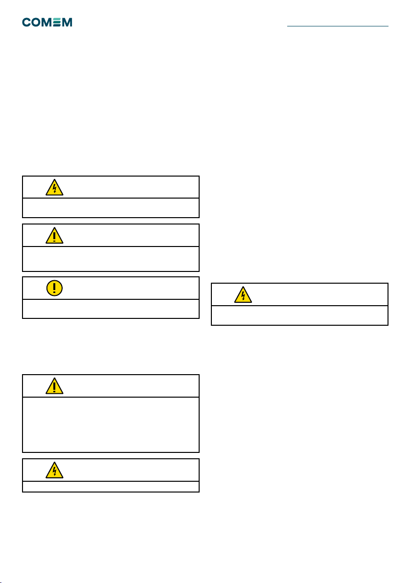
AVVERTIMENTO
AVVERTIMENTO
Il regolamento antincendio deve essere rigorosamente rispettato.
AVVERTIMENTO
ATTENZIONE
ATTENZIONE
NOTA
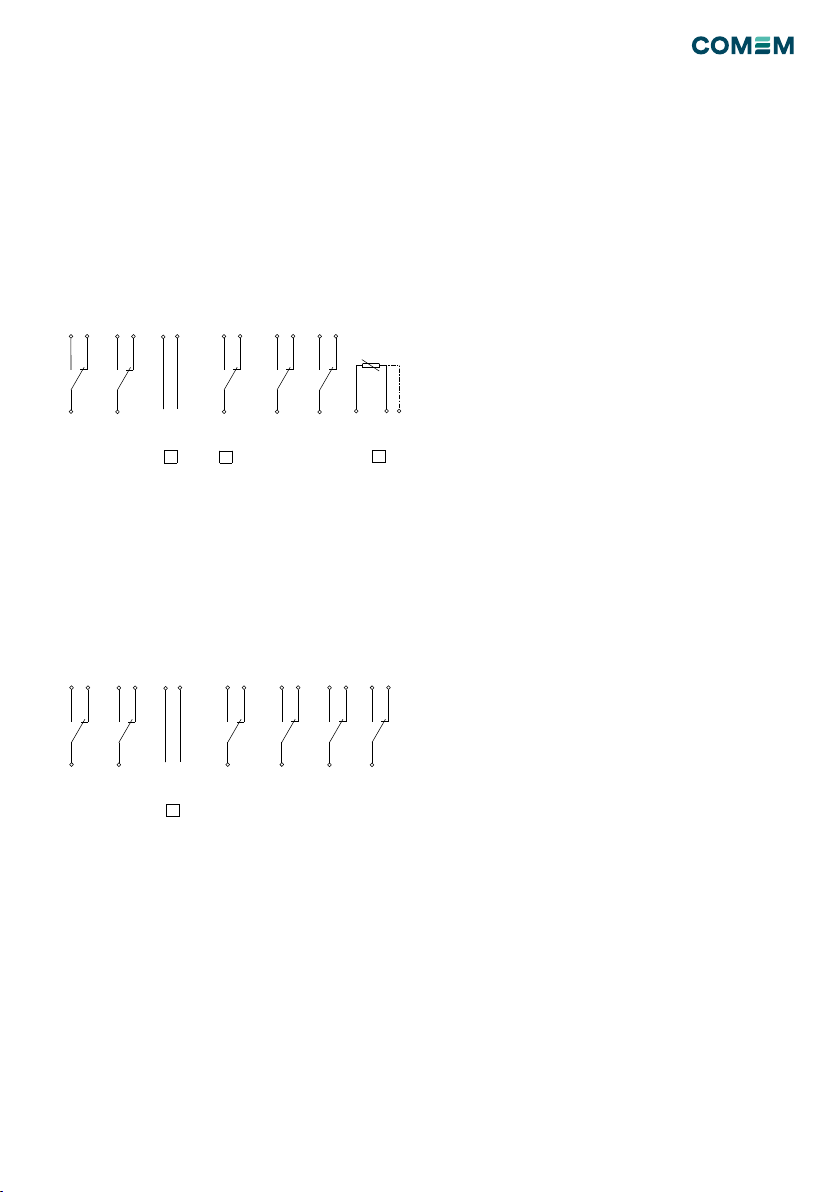
Il rilevatore integrato di sicurezza (RIS2) consta do un
robusto materiale plastico, resistente alle condizioni
ambientali più estreme, equipaggiato con diversi sensori
che monitorano costantemente i seguenti parametri del
trasformatore:
• Pressione
• Pressostato: apre/chiude un circuito alla pressione
regolata (da 100 a 500 mbar)
• Temperatura
• Termometro: rappresentazione visiva della
temperatura diretta dell’olio e massima raggiunta.
• Termostato “T2”: (allarme) apre/chiude un circuito al
raggiungimento della temperatura impostata (da 30°C
a 120°C)
• Termostato “T1”: (sgancio) apre/chiude un circuito al
raggiungimento della temperatura impostata (da 30°C
a 120°C)
• Livello del liquido
• Indicatore: rilevatore visivo di lieve variazione del livello
del liquido.
• Segnalatore: rilevatore visivo di consistente variazione
del livello d’olio con chiusura/apertura del circuito
elettrico
• Formazione di gas
• Segnalatore: apre/chiude un circuito al raggiungimento
della massima quantità di gas prodotta (170 cm3)
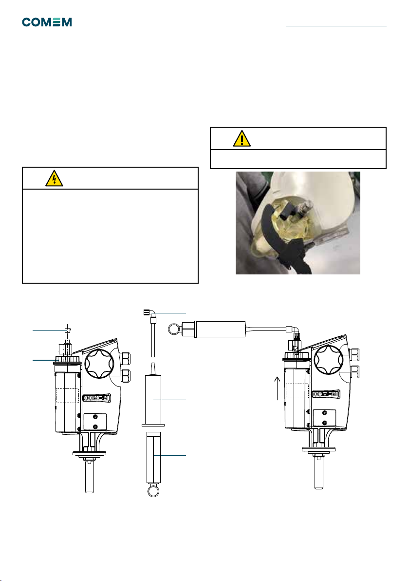
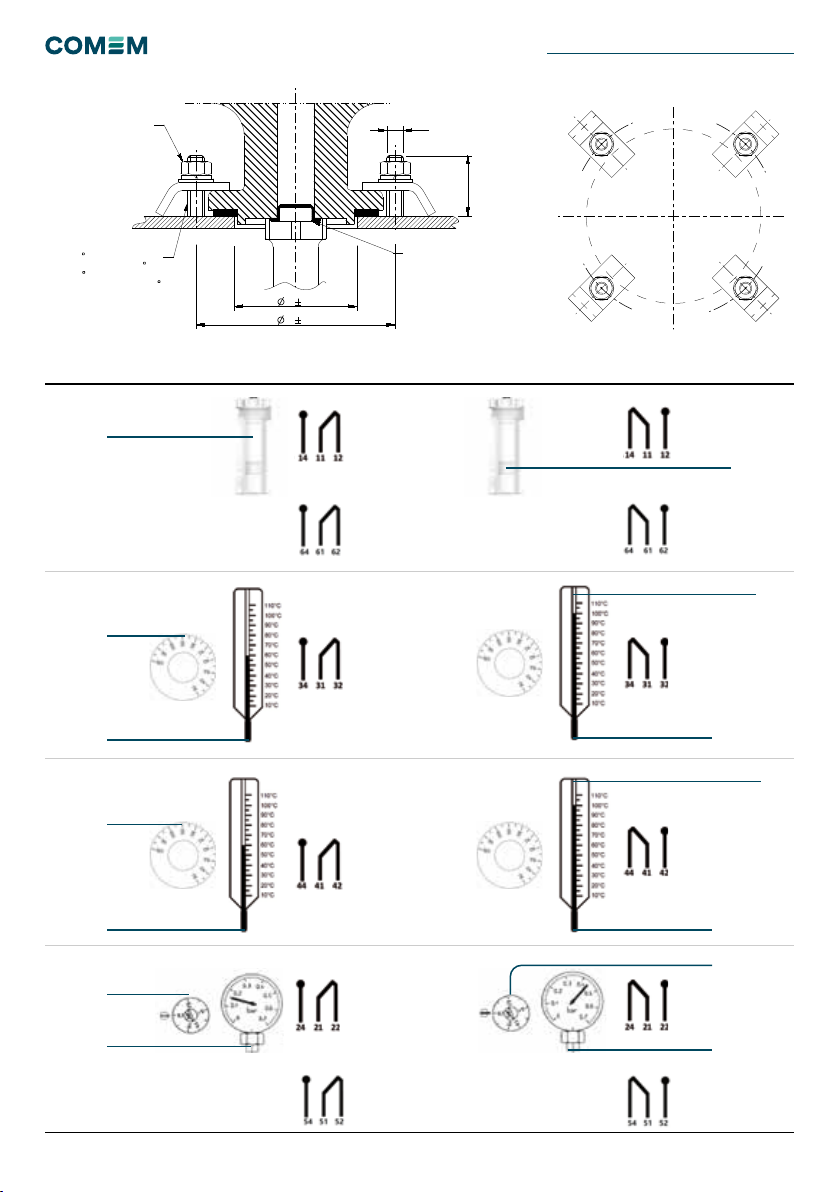
Istruzioni di montaggio
Applicazione su cassone del trasformatore
• Foro Ø 60 mm ± 1 mm su cassone
• Guarnizione piana (fornita a corredo)
• Staffe di bloccaggio in acciaio inossidabile (4 pezzi
forniti a corredo)
• Rosette piane UNI 6592 Ø 8,4 mm in inox (4 pezzi forniti
a corredo)
• Rosette elastiche UNI 1751Ø 8,4 mm in inox (4 pezzi
forniti a corredo)
• Dadi M8 UNI 5588 in inox (4 pezzi forniti a corredo).
Serrare a croce i dadi in posizione 1, 2, 3, 4 con una coppia
di 3/4 Nm; ripetere l’operazione nella stessa sequenza
no al raggiungimento del valore consigliato. Durante
il sollevamento del trasformatore, per la deformazione
del coperchio, potrebbe esserci una perdita di olio. Si
consiglia di utilizzare coperchi con spessore adeguato
(6-8 mm minimo).

10
Condizioni normali di funzionamento Condizioni di anomalia (intervento del rilevatore)
Su richiesta: doppio contatto di livello
Su richiesta: doppio contatto di pressione
Livello d’olio
Impostazione
temp. d’allarme
“T2”
Impostazione
temp. di sgancio
“T1”
Impostazione temp. d’allarme “T2”
Impostazione temp. di sgancio “T1”
Temperatura dell’olio
Pressione dell’olio
Impostazione di pressione
Temperatura dell’olio
Pressione dell’olio
Impostazione di
pressione
Figura 1
Tabella 1
RILEVATORI INTEGRATI DI SICUREZZA RIS2
Livello d’olio
D
C
B
A
654
3
21 7 8
E
F
A
B
C
D
E
F
1 2 3 4 5 6 7 8
This document is issued by means of a computerized system.
The digitally stored original is electronically approved. The
approved document has a date entered in the `Approved'-field.
A manual signature is not required.
DRAWING SHEET ISO 5457: 1999-A3T
We reserve all rights in this document and in the information
contained therein. Reproduction, use or disclosure to third
parties without express authority is strictly fobidden.
M8
30
97 2
60 1
1/11
A
Development
ND-091
SHEETITERREVSTATUSDOCUMENT ID
ITABB-9AAE306693 -
RESPONSIBLE DEPARTMENT
FISSAGGIO RIS/RIS2
COMEM
TITLE / SUPPLEMENTARY TITLECOMPANY
Component Drawing-
PROJECT IDWORK ORDER IDBASED ON DOC IDDOCUMENT KINDAPPROVED ON
--Diego Boro
APPROVED BYREVIEWED BYCREATED BY
© COPYRIGHT ALL RIGHTS RESERVED
PROTECTION CAP
REMOVE BEFORE
INSTALLATION!
N 4 THREADED PINS
AT 90 OR
N3 THREADED PINS
AT 120
1
2
3
4
TIGHNTENING TORQUE
6-8 Nm

11
Il tappo del serbatoio (5) deve essere chiuso a mano.
Alternativamente utilizzare lo strumento dedicato (figura 2)
ATTENZIONE
• Non utilizzare il rubinetto del dispositivo per il riempimento
del trasformatore ma solamente per il rabbocco a dispositivo
montato.
• Riempire d'olio il dispositivo fino a che il galleggiante si porta sulla
posizione di MAX. Durante tale fase tenere il rubinetto aperto.
• A riempimento completo, verificare (a mano) la chiusura del
rubinetto di sfiato e del tappo del serbatoio.
• Dopo la regolazione del termometro richiudere l'oblò.
• Verificare il serraggio a tenuta del pressacavo M25x1,5.
• Nel caso di variazione del livello o formazione di gas, il
galleggiante si posizionerà sul MIN facendo scattare il contatto.
• Ripristinare aggiungendo olio e sfiatando il gas accumulato.
AVVERTIMENTO
Avvertenze per il montaggio e l’uso
• Prima del montaggio del dispositivo, togliere il tappo di
protezione del foro per il passaggio olio.
• Assicurarsi che il piano d’appoggio sia liscio e piano.
• Per una perfetta tenuta si consiglia l’utilizzo di 4 prigionieri.
• Non verniciare il RIS durante la verniciatura del cassone.
• Montare il dispositivo dopo l’essiccazione del trafo.
• Togliere la tensione prima di intervenire sul RIS.
• Gli interventi sul RIS devono essere fatti solo dal
personale qualificato.
• COMEM non risponde per danni derivanti da anomalie di
montaggio, errate manovre o usi impropri.
• Non pulire il dispositivo con solventi, benzine o simili.
• Utilizzare un panno asciutto o imbevuto d’acqua.
• Non rimuovere il galleggiante del livello d’olio.
Istruzioni per il ripristino livello
Premessa
Il riempimento d’olio del dispositivo viene eseguito esclusi-
vamente dal costruttore del trasformatore a temperatura
ambiente. Alla messa in servizio il RIS2 deve essere
completamento pieno d’olio.
Figura 2
Figura 3
3
4
2
1
5
Se non ci fosse disponibilità d’olio per il rabbocco, COMEM
fornisce un corredo pompa per creare una pressione
negativa e ripristinare il livello d’olio.
Istruzioni per il corredo pompa
Le operazioni si eseguono nel seguente modo:
A. Aprire il rubinetto (installato sul tappo 5).
B. Assemblare la pompa del RIS2 come da figura (2, 3 e 4).
C. Rimuovere il tappo (1).
D. Avvitare la pompa (figura sulla destra).
E. Estraendo lo stantuffo aspirare la siringa, facendo
così innalzare il livello del serbatoio tramite la rimozione
dell’aria.
F. Chiudere il rubinetto (sopra 5) per reinserire lo stantuffo.
G. Ripetere le operazioni (A-F) no alla completa fuoriuscita
dell’aria.

12
Schema elettrico
Schema elettrico convenzionale
• Temp. sgancio “T1” (morsetti 44-41-42)
• Temp. allarme “T2” (morsetti 34-31-32)
• Pressione (morsetti 24-21-22)
• Livello olio(morsetti 14-11-12)
• Opzioni speciali (spuntate, ove presenti):
• 4-20 mA (segnale analogico)
• secondo contatto di pressione
• PT100
Figura 4
Figura 5
Schema elettrico “a 6 cont ti” – su richiesta
• Temp. sgancio “T1” (morsetti 44-41-42)
• Temp. allarme “T2” (morsetti 34-31-32)
• Pressione 1 (morsetti 24-21-22)
• Pressione 2 (morsetti 54-51-52)
• Livello olio 1(morsetti 14-11-12)
• Livello olio 2 (morsetti 64-61-62)
• Opzioni speciali (spuntate, ove presenti):
• 4-20 mA (segnale analogico)
D
C
B
E
F
1 2 3 4
This document is issued by means of a computerized system.
The digitally stored original is electronically approved. The
approved document has a date entered in the `Approved'-field.
A manual signature is not required.
We reserve all rights in this document and in the information
contained therein. Reproduction, use or disclosure to third
parties without express authority is strictly fobidden.
DRAWING SHEET ISO 5457: 1999-A4T
100
45
4
1/18
D
Released
D-4219
SHEETITERREVSTATUSDOCUMENT ID
ITABB-9AAE306693 New electrical scheme label for RIS2
RESPONSIBLE DEPARTMENT
ETICHETTA SCHEMA ELETTRICO RIS2 (NUOVA)
COMEM
TITLE / SUPPLEMENTARY TITLERESPONSIBLE COMPANY
Component Drawing2019-07-31
PROJECT IDWORK ORDER IDBASED ON DOC IDDOCUMENT KINDAPPROVED ON
Carlo CarolloDiego BoroDiego Boro
APPROVED BYREVIEWED BYCREATED BY
© COPYRIGHT ALL RIGHTS RESERVED
LAST REVISION
DESCRIPTION
MODIFICATA SERIGRAFIA ETICHETTA - Changed label
REPLACED
REVISION
C
TOLLERANZE GENERALI SECONDO - GENERAL TOLERANCES ACCORDING TO ISO 2768
m
SCALE
NO
MATERIAL WEIGHT - kg
ETICHETTA ADESIVA - Adesive label
-
PROCESS PART NUMBER
- - 5COD421900
42
44
41
TEMP.
TRIPPING
34 32
31
TEMP.
ALARM
54 52
51
24 22
21
PRESSURE
14 12
11
GAS
+ -
4-20 mA ABb
ELECTRICAL SCHEME (EN 50005 )
7x45
NOTE
SFONDO: RAL7032
SCRITTE: NERE
Background: RAL 7032
Writing: Black
Optional
PRESS. 2
Optional PT100
Optional
D
C
B
E
F
1 2 3 4
This document is issued by means of a computerized system.
The digitally stored original is electronically approved. The
approved document has a date entered in the `Approved'-field.
A manual signature is not required.
We reserve all rights in this document and in the information
contained therein. Reproduction, use or disclosure to third
parties without express authority is strictly fobidden.
DRAWING SHEET ISO 5457: 1999-A4T
100
45
4
1/15
A
Released
D-4231
SHEETITERREVSTATUSDOCUMENT ID
ITABB-9AAE306693 Electrical special scheme label for RIS2
RESPONSIBLE DEPARTMENT
ETICHETTA SCHEMA ELETTRICO RIS2 SPECIALE
COMEM
TITLE / SUPPLEMENTARY TITLERESPONSIBLE COMPANY
Component Drawing2019-11-19
PROJECT IDWORK ORDER IDBASED ON DOC IDDOCUMENT KINDAPPROVED ON
Carlo CarolloDiego BoroDiego Boro
APPROVED BYREVIEWED BYCREATED BY
© COPYRIGHT ALL RIGHTS RESERVED
LAST REVISION
DESCRIPTION
NUOVA EMISSIONE - Issue
REPLACED
REVISION
TOLLERANZE GENERALI SECONDO - GENERAL TOLERANCES ACCORDING TO ISO 2768
m
SCALE
NO
MATERIAL WEIGHT - kg
ETICHETTA ADESIVA - Adesive label
-
PROCESS PART NUMBER
- - 5COD423100
42
44
41
TEMP.
TRIPPING
34 32
31
TEMP.
ALARM
54 52
51
24 22
21
PRESSURE
1
14 12
11
GAS
1
+ -
4-20 mA
ELECTRICAL SCHEME (EN 50005 )
7x45
NOTE
SFONDO: RAL7032
SCRITTE: NERE
Background: RAL 7032
Writing: Black
Optional
PRESSURE
2
64 62
61
GAS
2
RILEVATORI INTEGRATI DI SICUREZZA RIS2

13
Caratteristiche generali
Grado di protezione (EN 60529) IP66
Tenuta alla nebbia salina 1000 h
Resistenza ai raggi ultravioletti (UNI-ISO 4892 / UNI-ISO 4582) 500 h
Intervallo di misurazione della temperatura Da -40°C a +120°C
Intervallo di temperatura ambiente Da -40°C a 55°C
Attacco del pressacavo M 25 x 1.5
Morsettiera (EN 50005 / EN 60947-7-1 / IEC 947-7-1) A norma
Sezione del lo da utilizzare sulla morsettiera Fino a 2.5 mm2
Pressione massima di esercizio 500 mbar
Caratteristiche elettriche Involucro isolato
Corrente Corrente alternata (C.A.) Corrente continua (C.C.)
Tipologia di
circuito
Ohmico Ohmico-induttivo
(cosφ > 0,5)
Ohmico Ohmico-induttivo
(L/R < 40ms)
Tensione 220 127 24
Capacità di
chiusura
Livello d’olio 2A 2A 2A 2A 2A 2A 2A 2A 2A 2A 2A 2A
Pressostato 6A 6A 6A 2A 2A 2A 0,6A 0,6A 0,6A 0,6A 0,6A 0,6A
Termostato 16A 16A 16A 4A 4A 4A 0,6A 0,6A 0,6A 0,2A 0,3A 1,8A
Caratteristiche generali
Descrizione delle funzioni presenti Valore di misura Verica
Livello dell’olio (galleggiante)
Il dispositivo rileva la formazione di gas o la variazione del livello dell’olio.
- per variazioni lievi (eventi di scarsa consistenza), il livello si posizionerà tra i
livelli di MIN - MAX posto sul serbatoio.
- per variazioni consistenti, il galleggiante scenderà no al MIN attivando il circuito
del contatto di allarme.
- il gas accumuato deve essere satato o prelevato dal rubinetto.
Massimo
150 cm3
Avvicinare un magnete al galleggiante
e trascinarlo verso il basso no
all’indicazione di minima (MIN).
Per ripristinare il galleggiante alla sua
posizione originario, trascinare verso
l’alto il magnete.
Pressione (pressostato)
Il dispositivo rileva la pressione interna del trasformatore.
La regolazione del valore di pressione impostato sul pressostato deve essere
eseguita a seconda delle caratteristiche costruttive dal trasformatore. Al
superamento di tale soglia, il dispositivo apre/chiude il relativo circuito di allarme.
Da 100 mbar a
500 mbar
Con almeno una pressione minima del
trasformatore di 100 mbar, portare al
minimo la mapola di regolazione del
pressostato.
Temperatura
Termostato “T2” di allarme
Il dispositivo rileva la temperatura interna dell’olio del trasformatore. La
regolazione del valore di temperatura impostato sul termostato “T2” è a seconda
delle caratteristiche del trasformatore. Superata tale soglia, il dispositivo apre/
chiude il relativo circuito di allarme.
Da 30°C a 120°C Accedere allo scomparto posteriore
del RIS. Portare a 0 (zero) la manopola
di regolazione del termostato di
allarme “T2”.
Termostato “T1” di sgancio
Il dispositivo rileva la temperatura interna dell’olio del trasformatore. La
regolazione del valore di temperatura impostato sul termostato “T1” è a seconda
delle caratteristiche del trasformatore. Superata tale soglia, il dispositivo apre/
chiude il relativo circuito di allarme.
Da 30°C a 120°C Accedere allo scomparto posteriore
del RIS. Portare a 0 (zero) la manopola
di regolazione del termostato di
sgancio “T1”.
Termometro
Il dispositivo rileva la temperatura interna del trasformatore che viene visualizzata
a quadrante . Il termometro è dotato di un indice di massima azzerabile.
Da 30°C a 160°C Per azzerare la lancetta di massima
rimuovere l’oblò protettivo e portare la
lancetta alla minima temperatura.
Tabella 4
Tabella 3
Tabella 2

14
Sicherheit Produktbeschreibung
Installation
Sicherheitshinweise
Stellen Sie sicher, dass die Person, die den
Sicherheitssensor installiert, in Betrieb nimmt und bedient:
• technisch qualiziert und kompetent ist.
• diese Montageanleitung in vollem Umfang beachtet.
Unsachgemäße Bedienung oder Fehlanwendungen
könnten Folgendes gefährden:
• Leib und Leben
• das Gerät oder andere Anlagen des Betreibers
• die korrekte Gerätefunktion
Die Sicherheitshinweise in diesem Handbuch werden
auf drei unterschiedliche Arten abgebildet, um wichtige
Informationen hervorzuheben.
Sicherheitshinweise zum Gerätebetrieb
Die elektrische Installation unterliegt den einschlägigen
nationalen Sicherheitsvorschriften.
Aus Sicherheitsgründen ist der Anschluss des
Erdungskabels obligatorisch.
Diese Informationen weisen auf besondere Gefahr für Leben
und Gesundheit hin. Die Nichtbeachtung einer solchen Warnung
kann zu schweren oder tödlichen Verletzungen führen.
Es ist wichtig, vor der Inbetriebnahme des Geräts die auf den
Typenschildern und in der Betriebsanleitung angegebenen
Grenzwerte zu beachten.
Alle maßgeblichen Brandschutzvorschriften müssen streng
beachtet werden.
Diese Informationen weisen auf besondere Gefahren für die
Anlage und/oder anderes Eigentum des Benutzers hin. Schwere
oder tödliche Verletzungen können nicht ausgeschlossen
werden.
Installation, elektrischer Anschluss und Montage des
Geräts müssen von Fachpersonal und ausschließlich in
Übereinstimmung mit dieser Betriebsanleitung vorgenommen
werden.
Es liegt in der Verantwortung des Benutzers sicherzustellen,
dass das Gerät nur bestimmungsgemäß verwendet wird.
Vermeiden Sie aus Sicherheitsgründen bitte jegliche unbefugten
und unsachgemäßen Eingriffe.
Diese Hinweise erteilen wichtige und spezische Informationen
bezüglich des Geräts.
WARNUNG
WARNUNG
WARNUNG
VORSICHT
VORSICHT
HINWEIS
Der integrierte Sicherheitssensor RIS2 besteht aus einem
widerstandsfähigen Kunststoffgehäuse, ist wasserdicht
und für extreme klimatische Bedingungen ausgelegt. Er
ist mit mehreren Messinstrumenten ausgestattet, die
die folgenden Betriebsbedingungen des Transformators
kontinuierlich überwachen:
• Druck
• Druckschalter: Er schließt/öffnet einen Kreislauf in
einem bestimmten Druckbereich (von 100 bis 500
mbar).
• Temperatur
• Thermometer: Anzeige der Öltemperatur und der max.
erreichten Temperatur.
• „T2“ Temperaturschalter: (Alarm) Er schließt/öffnet
einen Kreislauf bei einer vorgegebenen Temperatur
(30°C bis 120 °C).
• „T1“ Temperaturschalter: (Stopp) Er schließt/öffnet
einen Kreislauf bei einer vorgegebenen Temperatur
(30°C bis 120 °C).
• Ölstand
• Anzeige: Sie zeigt geringe Schwankungen des
Ölstands an.
• Detektor: Er zeigt deutliche Schwankungen des
Ölstands durch das Schließen/Öffnen eines
Stromkreises an.
• Entlüftung
• Sensor: Er schließt/öffnet einen Kreislauf, wenn das
max. zulässige Gasvolumen (max. 170 cm3) erreicht
ist.
Montageanleitung
Installation am Transformatorbehälter
• Durchmesser der Öffnung im Behälter: Ø 60 mm ± 1 mm
• Flache Dichtung (im Lieferumfang der Einheit enthalten)
• Befestigungsbügel aus Edelstahl (4 Stk.)
• Flache Unterlegscheiben aus Edelstahl nach DIN 6592
• Ø 8,4 mm (4 Stk.)
• Federscheiben aus Edelstahl nach DIN 1751 Ø 8,4 mm
(4 Stk.)
• M8-Muttern aus Edelstahl nach DIN 5588 (4 Stk.).
Die Muttern an 1, 2, 3 und 4 mit einem Drehmoment
von 3 Nm bis 4 Nm überkreuz anziehen. In der gleichen
Reihenfolge erneut anziehen, bis das empfohlene
Drehmoment (6 Nm bis 8 Nm) erreicht ist.
Wenn sich die Abdeckung des Transformators beim
Heben verformt, kann evtl. Öl austreten. Es wird
empfohlen, Abdeckungen mit einer geeigneten Stärke zu
verwenden (min. 6 - 8 mm).
INTEGRIERTE SICHERHEITSSENSOR RIS2

15
Normale Betriebsbedingungen Anormale Betriebsbedingungen (Auslösung des RIS2 von Comem)
Sonderoption: zwei Ölschalter
Ölstand
Temperatur-
einstellung für
Alarm „T2“
Temperatur-
einstellung für
Alarm „T1“
Temperatureinstellung für
Alarm „T2“
Temperatureinstellung
für Alarm „T1“
Ölstand
Öltemperatur
Öltemperatur
Öldruck
Druckeinstellung
Öltemperatur
Öltemperatur
Öldruck
Druckeinstellung
Abbildung 1
Tabelle 1
D
C
B
A
654
3
21 7 8
E
F
A
B
C
D
E
F
1 2 3 4 5 6 7 8
This document is issued by means of a computerized system.
The digitally stored original is electronically approved. The
approved document has a date entered in the `Approved'-field.
A manual signature is not required.
DRAWING SHEET ISO 5457: 1999-A3T
We reserve all rights in this document and in the information
contained therein. Reproduction, use or disclosure to third
parties without express authority is strictly fobidden.
M8
30
97 2
60 1
1/11
A
Development
ND-091
SHEETITERREVSTATUSDOCUMENT ID
ITABB-9AAE306693 -
RESPONSIBLE DEPARTMENT
FISSAGGIO RIS/RIS2
COMEM
TITLE / SUPPLEMENTARY TITLECOMPANY
Component Drawing-
PROJECT IDWORK ORDER IDBASED ON DOC IDDOCUMENT KINDAPPROVED ON
--Diego Boro
APPROVED BYREVIEWED BYCREATED BY
© COPYRIGHT ALL RIGHTS RESERVED
PROTECTION CAP
REMOVE BEFORE
INSTALLATION!
N 4 THREADED PINS
AT 90 OR
N3 THREADED PINS
AT 120
1
2
3
4
TIGHNTENING TORQUE
6-8 Nm

16
Es wird empfohlen die Kappe 5 nicht mit Werkzeug oder
einem Schraubenschlüssel zu schließen. Es darf höchsten ein
spezielles Werkzeug verwendet werden: (siehe Abbildung 2)
VORSICHT
• Den Öllter am RIS2 von Comem nicht zum Füllen des
Transformators verwenden, sondern nur zum Nachfüllen des
Gerätes.
• Beim Füllen des RIS2 mit Öl darauf achten, dass der
Entlüftungshahn offen ist und so viel einfüllen, dass der
Schwimmer auf „MAX“ steht.
• Nach dem Füllen den Entlüftungshahn schließen und die Kappe
wieder montieren. Sie müssen dicht sein. Nur mit der Hand
anziehen, es ist kein Werkzeug erforderlich.
• Nach dem Einstellen des Zeigers des Thermometers überprüfen,
ob das Schutzglas fest sitzt. Nur von Hand anziehen.
• Überprüfen, ob die Kabeldurchführung (M 25 x 1,5) fest sitzt.
• Bei größeren Ölstandschwankungen oder einer starken
Gasentwicklung erreicht der Schwimmer die „MIN“-Stellung und
löst den Alarmschalter aus, dann muss das Gas entlüftet oder Öl
nachgefüllt werden.
WARNUNG
Installation
• Bevor mit der Installation des Gerätes begonnen wird,
die Schutzkappe von der Ölauslassöffnung abnehmen.
• Überprüfen, ob die Auflagefläche des Lagers glatt und
eben ist.
• Es wird eine Befestigung mit vier Bolzen empfohlen.
• RIS2 muss dann bei evtl. Lackierarbeiten geschützt
werden.
• RIS2 darf erst nach dem Trocknen des Transformators
installiert werden.
• Vor allen Arbeiten am RIS2 muss die Stromversorgung
ausgeschaltet werden.
• RIS2 muss von Fachpersonal bedient und gewartet
werden.
• Bei einer fehlerhaften Installation oder unsachgemäßen
Verwendung lehnt COMEM jegliche Haftung ab.
• Zum Reinigen keine starken Lösungsmittel oder Benzol
verwenden. Es sollte ein feuchtes Tuch verwendet
werden.
• Den Schwimmer nicht aus dem RIS2 herausnehmen.
Nachfüllen des RIS2
Vorwort
Das Gerät wird ausschließlich vom Hersteller des
Transformators und bei Umgebungstemperatur mit Öl
befüllt. Bevor der Transformator mit Strom versorgt wird,
überprüfen, ob der RIS2 von Comem vollständig mit Öl
gefüllt ist. Aus verschiedenen Gründen könnte der Ölstand
unter dem eingestellten Füllstand liegen. Wenn der
Transformator aufgrund der hohen Umgebungstemperatur
oder seines Betriebs warm ist, steigt u. U. der Druck in
seinem Inneren, was zu einem sichtbaren Abfall des
Ölstands in der Kammer des Gerätes führt.
Abbildung 2
Abbildung 3
INTEGRIERTE SICHERHEITSSENSOR RIS2
3
4
2
1
5
Wenn kein Öl zum Nachfüllen verfügbar ist, kann ein
Zubehörset von COMEM für die Pumpe verwendet werden,
um einen Unterdruck in dem Gerät zu erzeugen und den
Ölstand wiederherzustellen.

17
Anleitung
Wie folgt vorgehen:
A. Öffne den benzinhahn (über 5)
B. Montieren sie das pneumatische pumpenset für RIS2
wie in der abbildung (2, 3 und 4)
C. Entfernen sie die kappe (1)
D. Schrauben sie die pumpe in den benzinhahn (abbildung
auf der recht).
E) Ziehen sie den kolben zurück, damit die luft aus RIS2
strömt und der Ölstand ansteigt
F. Schließen sie den benzinhahn (über 5), um sich zu
bewegen wieder den kolben in die ausgangsposition
ohne bringen sie luft in das RIS2.
G. Wiederholen sie die obigen schritte (A-F), bis
dergesamte luftstrom aus dem RIS2.
Elektrischer Anschluss
Schaltplan
• Temp. AUSLÖSER „T1“ (Anschlussklemmen 44-41-42)
• Temp. ALARM „T2“ (Anschlussklemmen 34-31-32)
• Druck (Anschlussklemmen 24-21-22)
• Ölstand (Anschlussklemmen 14-11-12)
• Optionen (falls vorhanden markiert):
• 4 - 20 mA
• 2. Druckschalter
• PT100
Abbildung 4
Abbildung 5
Spezieller Schaltplan für „6 Schalter“ - auf Anfrage
• Temp. AUSLÖSER „T1“ (Anschlussklemmen 44-41-42)
• Temp. ALARM „T2“ (Anschlussklemmen 34-31-32)
• Druck 1 (Anschlussklemmen 24-21-22)
• Druck 2 (Anschlussklemmen 54-51-52)
• Ölstand 1 (Anschlussklemmen 14-11-12)
• Ölstand 2 (Anschlussklemmen 64-61-62)
• Option (falls vorhanden markiert):
• 4 - 20 mA
D
C
B
E
F
1 2 3 4
This document is issued by means of a computerized system.
The digitally stored original is electronically approved. The
approved document has a date entered in the `Approved'-field.
A manual signature is not required.
We reserve all rights in this document and in the information
contained therein. Reproduction, use or disclosure to third
parties without express authority is strictly fobidden.
DRAWING SHEET ISO 5457: 1999-A4T
100
45
4
1/18
D
Released
D-4219
SHEETITERREVSTATUSDOCUMENT ID
ITABB-9AAE306693 New electrical scheme label for RIS2
RESPONSIBLE DEPARTMENT
ETICHETTA SCHEMA ELETTRICO RIS2 (NUOVA)
COMEM
TITLE / SUPPLEMENTARY TITLERESPONSIBLE COMPANY
Component Drawing2019-07-31
PROJECT IDWORK ORDER IDBASED ON DOC IDDOCUMENT KINDAPPROVED ON
Carlo CarolloDiego BoroDiego Boro
APPROVED BYREVIEWED BYCREATED BY
© COPYRIGHT ALL RIGHTS RESERVED
LAST REVISION
DESCRIPTION
MODIFICATA SERIGRAFIA ETICHETTA - Changed label
REPLACED
REVISION
C
TOLLERANZE GENERALI SECONDO - GENERAL TOLERANCES ACCORDING TO ISO 2768
m
SCALE
NO
MATERIAL WEIGHT - kg
ETICHETTA ADESIVA - Adesive label
-
PROCESS PART NUMBER
- - 5COD421900
42
44
41
TEMP.
TRIPPING
34 32
31
TEMP.
ALARM
54 52
51
24 22
21
PRESSURE
14 12
11
GAS
+ -
4-20 mA ABb
ELECTRICAL SCHEME (EN 50005 )
7x45
NOTE
SFONDO: RAL7032
SCRITTE: NERE
Background: RAL 7032
Writing: Black
Optional
PRESS. 2
Optional PT100
Optional
D
C
B
E
F
1 2 3 4
This document is issued by means of a computerized system.
The digitally stored original is electronically approved. The
approved document has a date entered in the `Approved'-field.
A manual signature is not required.
We reserve all rights in this document and in the information
contained therein. Reproduction, use or disclosure to third
parties without express authority is strictly fobidden.
DRAWING SHEET ISO 5457: 1999-A4T
100
45
4
1/15
A
Released
D-4231
SHEETITERREVSTATUSDOCUMENT ID
ITABB-9AAE306693 Electrical special scheme label for RIS2
RESPONSIBLE DEPARTMENT
ETICHETTA SCHEMA ELETTRICO RIS2 SPECIALE
COMEM
TITLE / SUPPLEMENTARY TITLERESPONSIBLE COMPANY
Component Drawing2019-11-19
PROJECT IDWORK ORDER IDBASED ON DOC IDDOCUMENT KINDAPPROVED ON
Carlo CarolloDiego BoroDiego Boro
APPROVED BYREVIEWED BYCREATED BY
© COPYRIGHT ALL RIGHTS RESERVED
LAST REVISION
DESCRIPTION
NUOVA EMISSIONE - Issue
REPLACED
REVISION
TOLLERANZE GENERALI SECONDO - GENERAL TOLERANCES ACCORDING TO ISO 2768
m
SCALE
NO
MATERIAL WEIGHT - kg
ETICHETTA ADESIVA - Adesive label
-
PROCESS PART NUMBER
- - 5COD423100
42
44
41
TEMP.
TRIPPING
34 32
31
TEMP.
ALARM
54 52
51
24 22
21
PRESSURE
1
14 12
11
GAS
1
+ -
4-20 mA
ELECTRICAL SCHEME (EN 50005 )
7x45
NOTE
SFONDO: RAL7032
SCRITTE: NERE
Background: RAL 7032
Writing: Black
Optional
PRESSURE
2
64 62
61
GAS
2

18
Allgemeine Angaben
Schutzgrad (DIN EN 60529) IP 66
Dichtheit gegenüber Salzsprühnebel 1000 h
Widerstandsfähigkeit gegen UV-Bestrahlung
(DIN EN ISO 4892 / DIN EN ISO 4582)
500 h
Messbereich -40°C bis +120°C
Umgebungstemperatur -40 °C bis 55 °C
Kabelanschluss M 25 x 1,5
Kabeldose (DIN EN 50005 / DIN EN 60947-7-1 / IEC 947-7-1) Gemäß Norm
Für den Klemmenkasten zu verwendender Kabelquerschnitt bis 2,5 mm2
Max. Nenndruck 500 mbar
Elektrische Kenndaten Doppelte Isolierung
Strom AC DC
Schaltungstyp Ohmsch Ohmsch induktiv
(cosφ > 0,5)
Ohmsch Ohmsch induktiv
(L/R < 40 ms)
Spannung 220 127 24
Elektrische
Schaltleistung
Ölstand 2A 2A 2A 2A 2A 2A 2A 2A 2A 2A 2A 2A
Druckschalter 6A 6A 6A 2A 2A 2A 0,6 A 0,6 A 0,6 A 0,6 A 0,6 A 0,6 A
Thermostat 16A 16A 16A 4A 4A 4A 0,6 A 0,6 A 0,6 A 0,2 A 0,3 A 1,8 A
Technische Merkmale
Beschreibung und Funktionen Messwert Überprüfung des Testwertes
Ölstand (Schwimmer)Das Gerät zeigt jede Gasentwicklung oder Schwankung des
Ölstands an.
- Bei geringen Schwankungen des Ölstands oder einer unbedeutenden
Gasentwicklung steht der Schwimmer zwischen der „MIN“ und „MAX“ auf der
Anzeige.
- Bei einer stärkeren Schwankung des Ölstands oder einer starken Gasentwicklung
bleibt der Schwimmer auf „MIN“ stehen und die Alarmschaltung wird geöffnet/
geschlossen.
- Angesammeltes Gas kann über das entsprechende Ventil abgelassen werden.
Max. 150 cm3Den Magneten in der Nähe des
Schwimmers ausndig machen
(zwischen MAX und MIN). Ihn nach
unten drücken, bis er „MIN“ erreicht
hat.
Um den Schwimmer wieder in seine
richtige Stellung zurückzusetzen, den
Magneten nach oben und abziehen.
Druck (Druckschalter)
Mit dieser Funktion wird der Druck im Transformator gemessen. Der Normalwert
muss vom Betreiber und nach den Anweisungen des Herstellers des
Transformators eingestellt werden. Wenn der Druck einen voreingestellten Wert
überschreitet, wird über einen Wechsler die Alarmschaltung ausgelöst.
100 mbar bis
500 mbar
Bei einem Innendruck von mindestens
100 mbar den Einstellknopf des
Druckschalters auf Minimum
einstellen.
Temperatur
„T2“ Temperaturschalter (Alarm)
Mit dieser Funktion wird die Öltemperatur im Transformator gemessen.
Der normale Betriebswert muss vom Betreiber und nach den Anweisungen des
Herstellers des Transformators eingestellt werden. Bei einer voreingestellten
Temperatur wird über einen Wechsler die Alarmschaltung ausgelöst (T2).
30 °C bis 120 °C Mit beiden Händen die hintere
Abdeckung öffnen, dabei nicht nur an
einer Seite ziehen.
Der Einstellknopf des Alarmschalters
„T2“ muss auf den Mindestwert
eingestellt werden.
„T1“ Temperaturschalter (Stopp)
Mit dieser Funktion wird die Öltemperatur im Transformator gemessen.
Der normale Betriebswert muss vom Betreiber und nach den Anweisungen des
Herstellers des Transformators eingestellt werden. Bei einer voreingestellten
Temperatur wird über einen Wechsler die Stoppschaltung ausgelöst (T1).
30 °C bis 120 °C Der Einstellknopf des Stopp-Schalters
„T1“ muss auf den Mindestwert
eingestellt werden.
Der Einstellknopf des Stopp-Schalters
„T1“ muss auf den Mindestwert
eingestellt werden.
Thermometer
Das Gerät misst die Temperatur im Transformator. Sie kann außen am Gerät durch
das Schutzglas abgelesen werden.
Das Thermometer ist mit einem verstellbaren Zeiger ausgestattet.
30 °C bis 160°C Um den Zeiger auf den Mindestwert
einzustellen, muss das Schutzglas
abgeschraubt werden.
Tabelle 4
Tabelle 3
Tabelle 2
INTEGRIERTE SICHERHEITSSENSOR RIS2

19
Beschreibung und Funktionen Messwert Überprüfung des Testwertes
Ölstand (Schwimmer)Das Gerät zeigt jede Gasentwicklung oder Schwankung des
Ölstands an.
- Bei geringen Schwankungen des Ölstands oder einer unbedeutenden
Gasentwicklung steht der Schwimmer zwischen der „MIN“ und „MAX“ auf der
Anzeige.
- Bei einer stärkeren Schwankung des Ölstands oder einer starken Gasentwicklung
bleibt der Schwimmer auf „MIN“ stehen und die Alarmschaltung wird geöffnet/
geschlossen.
- Angesammeltes Gas kann über das entsprechende Ventil abgelassen werden.
Max. 150 cm3Den Magneten in der Nähe des
Schwimmers ausndig machen
(zwischen MAX und MIN). Ihn nach
unten drücken, bis er „MIN“ erreicht
hat.
Um den Schwimmer wieder in seine
richtige Stellung zurückzusetzen, den
Magneten nach oben und abziehen.
Druck (Druckschalter)
Mit dieser Funktion wird der Druck im Transformator gemessen. Der Normalwert
muss vom Betreiber und nach den Anweisungen des Herstellers des
Transformators eingestellt werden. Wenn der Druck einen voreingestellten Wert
überschreitet, wird über einen Wechsler die Alarmschaltung ausgelöst.
100 mbar bis
500 mbar
Bei einem Innendruck von mindestens
100 mbar den Einstellknopf des
Druckschalters auf Minimum
einstellen.
Temperatur
„T2“ Temperaturschalter (Alarm)
Mit dieser Funktion wird die Öltemperatur im Transformator gemessen.
Der normale Betriebswert muss vom Betreiber und nach den Anweisungen des
Herstellers des Transformators eingestellt werden. Bei einer voreingestellten
Temperatur wird über einen Wechsler die Alarmschaltung ausgelöst (T2).
30 °C bis 120 °C Mit beiden Händen die hintere
Abdeckung öffnen, dabei nicht nur an
einer Seite ziehen.
Der Einstellknopf des Alarmschalters
„T2“ muss auf den Mindestwert
eingestellt werden.
„T1“ Temperaturschalter (Stopp)
Mit dieser Funktion wird die Öltemperatur im Transformator gemessen.
Der normale Betriebswert muss vom Betreiber und nach den Anweisungen des
Herstellers des Transformators eingestellt werden. Bei einer voreingestellten
Temperatur wird über einen Wechsler die Stoppschaltung ausgelöst (T1).
30 °C bis 120 °C Der Einstellknopf des Stopp-Schalters
„T1“ muss auf den Mindestwert
eingestellt werden.
Der Einstellknopf des Stopp-Schalters
„T1“ muss auf den Mindestwert
eingestellt werden.
Thermometer
Das Gerät misst die Temperatur im Transformator. Sie kann außen am Gerät durch
das Schutzglas abgelesen werden.
Das Thermometer ist mit einem verstellbaren Zeiger ausgestattet.
30 °C bis 160°C Um den Zeiger auf den Mindestwert
einzustellen, muss das Schutzglas
abgeschraubt werden.
Seguridad Descripción del producto
Instalación
Instrucciones de seguridad
Asegúrese de que toda persona que instale, ponga en
funcionamiento y haga funcionar el detector de seguridad
• esté técnicamente cualicado y sea competente.
• cumple todas las instrucciones de montaje.
Unas operaciones no correctas o un mal uso puede
suponer un peligro para:
• la integridad física y los miembros del cuerpo
• el equipo y otros activos del operador
• el buen funcionamiento del equipo
En este manual, las instrucciones de seguridad se
muestran de tres maneras diferentes para destacar la
información importante.
Notas de seguridad sobre el funcionamiento del equipo
La instalación eléctrica está sujeta las relativas reglas de
seguridad nacionales.
Es obligatorio conectar el cable de tierra por razones de
seguridad.
Esta información indica un peligro grave para la integridad física
y la salud. Si no se tiene en cuenta esta advertencia, se pueden
producir heridas graves o incluso mortales.
Es importante respetar los valores límite indicados en la placa
de características y en el manual antes de poner en marcha el
dispositivo.
Deben respetarse estrictamente todas las normas de protección
contra incendios pertinentes.
Esta información indica un peligro especial para el equipo
y/o otros bienes del usuario. No puede descartarse que se
produzcan accidentes graves o incluso mortales.
La instalación, la conexión eléctrica y el montaje del dispositivo
deben ser realizados por personal cualicado y sólo de acuerdo
con este manual de instrucciones.
Es responsabilidad del usuario asegurarse de que el dispositivo
se utilice únicamente para la aplicación especicada.
Por cuestiones de seguridad, evite cualquier trabajo no
autorizado e inadecuado.
Estas notas dan información importante o especíca sobre el
equipo.
ADVERTENCIA
ADVERTENCIA
ADVERTENCIA
PRECAUCIÓN
PRECAUCIÓN
NOTA
El detector de seguridad integrado RIS2 está compuesto
por un robusto cuerpo de plástico, estanco y resistente
a climas extremos, con una serie de instrumentos
que mantienen un control constante de las siguientes
condiciones de funcionamiento del transformador:
• Presión
• Presostato: cierra/abre un circuito al variar la presión
(de 100 a 500 mbar).
• Temperatura
• Termómetro: indicación visual de la temperatura del
aceite y de la temperatura máxima alcanzada.
• “T2” Interruptor del termostato: (alarma) cierra/abre
un circuito a un nivel de temperatura predeterminado
(desde 30°C hasta 120°C).
• “T1” Interruptor del termostato: (parada) cierra/abre
un circuito a un nivel de temperatura predeterminado
(desde 30°C hasta 120°C).
• Nivel de aceite
• Indicador: indicador visual de una ligera variación del
nivel de aceite.
• Detector: detector visual de variación signicativa
del nivel de aceite mediante el cierre/apertura de un
circuito eléctrico.
• Gaseado
• Detector: cierra/abre un circuito cuando se alcanza el
volumen máximo de gas (máx. 170 cm3)
Instrucciones de montaje
Aplicación a una depósito del transformador
• Agujero de Ø 60 mm ± 1 mm de diámetro en el depósito
• Junta plana (suministrada con la unidad)
• Soportes de jación de acero inoxidable (4 unidades
embaladas)
• Arandelas planas de acero inoxidable según UNI 6592
• Ø 8,4 mm (4 unidades embaladas)
• Arandelas elásticas de acero inoxidable según UNI 1751
Ø 8,4 mm (4 unidades embaladas)
• Tuercas M8 de acero inoxidable según UNI 5588 (4
unidades embaladas).
Apretar las tuercas en posición 1,2,3,4 con tuerca de par
3 Nm a 4 Nm en cruz; repetir la operación siguiendo la
misma secuencia hasta alcanzar el valor sugerido (6 Nm
a 8 Nm).
Debido a la deformación de la cubierta durante el
levantamiento del transformador, podría producirse una
fuga de aceite. Se sugiere utilizar cubiertas de un grosor
adecuado (mín. 6-8 mm).

20
Condiciones normales de trabajo Condiciones de las anomalías (intervención RIS2 Comem)
Opción especial: interruptores de
aceite dobles
Opción especial: interruptores de
aceite dobles
Nivel de aceite
Alarma de ajuste
de temperatura
“T2”
Alarma de
ajuste de
temperatura
“T1”
Alarma de ajuste de
temperatura “T2”
Alarma de ajuste de
temperatura “T1”
Nivel
de
aceite
Temperatura del
aceite
Temperatura del aceite
Presión del aceite
Ajuste de la presión
Temperatura del aceite
Presión del aceite
Ajuste de la
presión
Figura 1
Tabla 1
DETECTOR DE SEGURIDAD INTEGRADO RIS2
D
C
B
A
654
3
21 7 8
E
F
A
B
C
D
E
F
1 2 3 4 5 6 7 8
This document is issued by means of a computerized system.
The digitally stored original is electronically approved. The
approved document has a date entered in the `Approved'-field.
A manual signature is not required.
DRAWING SHEET ISO 5457: 1999-A3T
We reserve all rights in this document and in the information
contained therein. Reproduction, use or disclosure to third
parties without express authority is strictly fobidden.
M8
30
97 2
60 1
1/11
A
Development
ND-091
SHEETITERREVSTATUSDOCUMENT ID
ITABB-9AAE306693 -
RESPONSIBLE DEPARTMENT
FISSAGGIO RIS/RIS2
COMEM
TITLE / SUPPLEMENTARY TITLECOMPANY
Component Drawing-
PROJECT IDWORK ORDER IDBASED ON DOC IDDOCUMENT KINDAPPROVED ON
--Diego Boro
APPROVED BYREVIEWED BYCREATED BY
© COPYRIGHT ALL RIGHTS RESERVED
PROTECTION CAP
REMOVE BEFORE
INSTALLATION!
N 4 THREADED PINS
AT 90 OR
N3 THREADED PINS
AT 120
1
2
3
4
TIGHNTENING TORQUE
6-8 Nm
Table of contents
Languages:
Other COMEM Industrial Equipment manuals
Popular Industrial Equipment manuals by other brands

ABB
ABB HT613844 Operation manual

Stoll
Stoll GLOBAL Operating and maintenance manual

Spirax Sarco
Spirax Sarco EasiHeat Installation and maintenance instructions

Beckhoff
Beckhoff EPX1058-0022 operating manual

Autz + Herrmann
Autz + Herrmann ROTOCLEAR S operating manual

Siemens
Siemens SIVACON S operating instructions