COMEM eSDB10 User manual

Self-dehydrating breathers eSDB
10/15/30
EN-IT-DE-ES-FR
INSTRUCTION MANUAL

2
CONTENT INDEX
Content index
Safety ...........................................................4
Product description ......................................4
Installation....................................................6
Electrical connection....................................8
Technical features........................................9
Applications................................................10
Operation and maintenance .......................10
Appendix A - Options..................................11
Appendix B
Overvoltage protection replacement
instruction ..................................................12
Appendix C - How to operate the menu......54
Appendix D - MODBUS communication......59
Appendix E - Drawings................................60
Indice dei contenuti
Sicurezza....................................................15
Descrizione del prodotto ............................15
Installazione ...............................................17
Connessioni elettriche................................19
Caratteristiche tecniche .............................20
Applicazioni................................................21
Funzionamento e manutenzione ................21
Appendice A - Opzioni ................................22
Appendice B
Istruzione per la sostituzione della
protezione da sovratensione .....................23
Appendice C - Funzionamento del menu....25
Appendice D - Comunicazione MODBUS....59
Appendice E - Disegni.................................60
Inhalt
Sicherheit ...................................................26
Produktbeschreibung .................................26
Installation..................................................28
Elektrischer Anschluss ...............................30
Technische Merkmale ................................31
Anwendungen.............................................32
Betrieb und Wartung...................................32
Anhang A - Optionen...................................33
Anhang B
Anleitung zum Auswechseln des
Überspannungsschutzes............................34
Anhang C - Menübedienung .......................36
Anhang D - MODBUS-Kommunikation........59
Anhang E - Zeichnungen ............................60
Índice de contenidos
Seguridad ...................................................37
DescripciÓn del producto............................37
InstalaciÓn..................................................39
ConexiÓn eléctrica......................................41
Carateristicas técnicas...............................42
Aplicaciones...............................................43
Funcionamento y mantenimiento...............43
Apéndice A - Opciones ...............................44
Apéndice B
Instrucciones de sustitución de la
protección contra sobretensiones .............45
Apéndice C - Uso de los menus..................47
Apéndice D - Comunicación MODBUS........59
Apéndice E - Dibujos ..................................60

3
Index du contenu
Securitè ......................................................48
Description du produit................................48
Installation..................................................50
Raccordement électrique ...........................52
Caractéristiques techniques.......................53
Applications................................................54
Utilisation et entretien ................................54
Annexe A - Options.....................................55
Annexe B
Instructions de remplacement de la
protection contre les surtensions ..............56
Annexe C - Opération de menu...................58
Annexe D - Communication MODBUS ........59
Annexe E - Dessins ....................................60

4
Safety Product description
Safety instructions
Make sure that any person installing, taking into operation
and operating the self-dehydrating breather:
• is technically qualified and competent
• fully complies with these assembling instructions
Improper operations or misuse could cause danger to:
• life and limb
• the equipment and other assets of the operator
• the equipment proper function
Safety instructions in this manual are shown in three
different forms to emphasize important information.
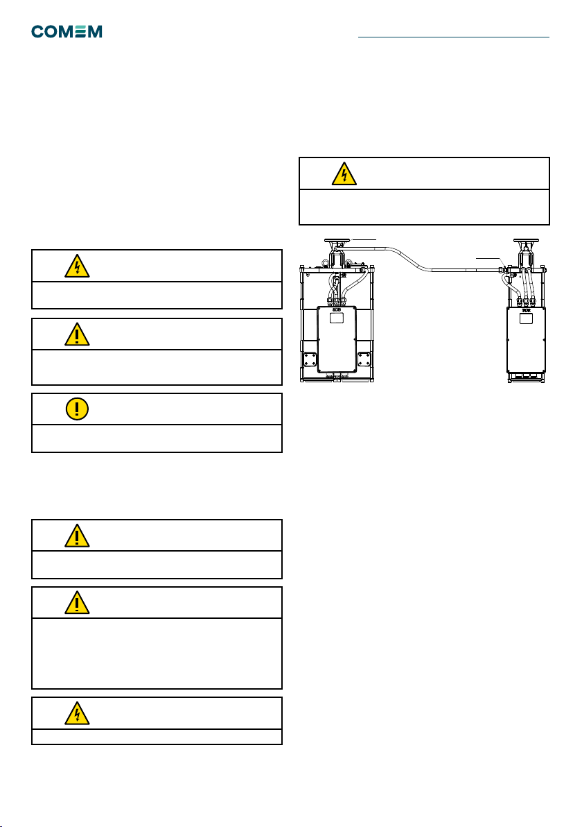
Safety notes on the equipment operation
Electrical installation is subject to the relevant national
safety rules.
It is mandatory to connect the grounding cable.
This information indicates particular danger to life and health.
Disregarding such a warning can lead to serious or fatal injury.
It is important to observe the limit values indicated on
the nameplate and in the operating instruction before
commissioning the device.
All relevant fire protection regulation must be strictly observed.
This information indicates particular danger to equipment or
other property of the user. Serious or fatal injury cannot be
excluded.
Installation, electrical connection and fitting the device may only
be performed by qualified personnel and only in accordance
with this instruction manual. It is the responsibility of the user
to ensure that the device is used for specified application only.
For safety reasons, please avoid any unauthorized and improper
usage.
During the regeneration phase, the surface temperature
increases. Touching the surface is dangerous.
This notes give important or specific information concerning the
equipment or as to work with the equipment.
WARNING
WARNING
WARNING
CAUTION
CAUTION
CAUTION
NOTE
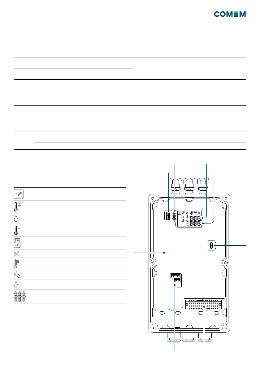
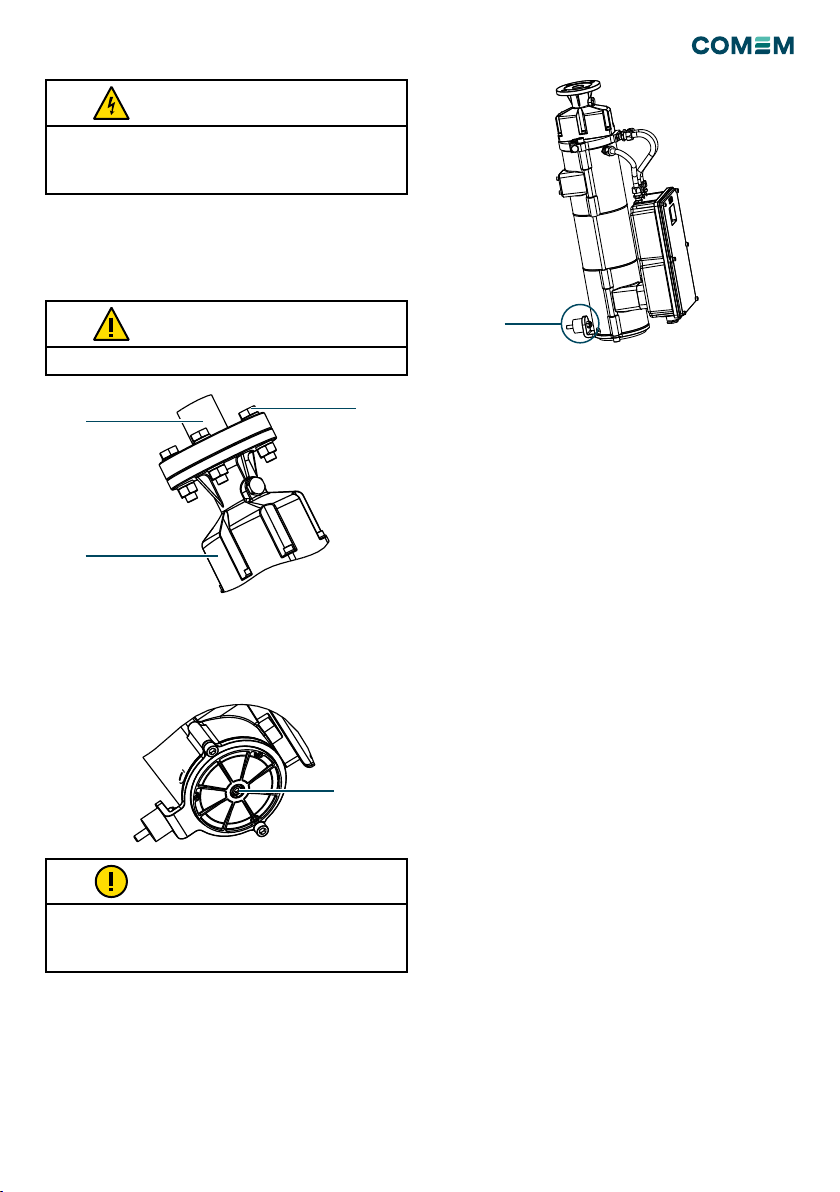
The dehydrating breather is used for oil-insulated tran-
sformer and on-load tap-changer to dry the air which is
suctioned in by the oil conservator during the thermal
contraction of the oil mass.
During the normal operation the oil conservator intakes
air that passes through the metallic filter (Fig.5-11/A). The
metallic filter stops dust, sand and other particles from
the contaminating air. The air then passes through the
tank 1 (Fig.16-17-18/1). The salt tank is filled with silica
gel that absorbs the moisture.
When the silica gel absorbs the moisture, the weight of the
salt increases and is constantly monitored by a weighing
cell. When the weight increases and exceeds the pre-set
value a solenoid valve blocks the passage of air through
salt tank 1 and deviates through the “plenum chamber” 2
(Fig. 16-17-18/2)(for eSDB10 it deviates the air through
the main self-dehydrating breather eSDB-15, eSDB-30). At
the same time, a heating system inside tank 1 is activated.
The water vapor leaving the silica gel is expelled outward
by a fan that also dissipates the heat.
Inside the tank, a probe controls the temperature of the
heating element.
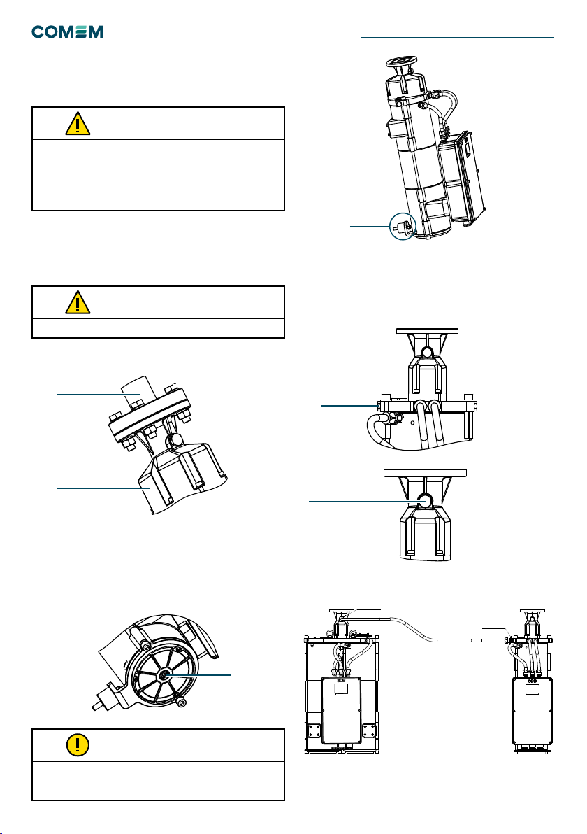
After the silica gel regeneration in tank 1, the solenoid
valve is de-energized and the airflow through tank 2 is
inhibited. The salt in this tank (2) is also dehydrated,
regeneration of the salt in tank 2 follows automatically
(not for eSDB-10).
No maintenance is required for replacement and
regeneration of the desiccant.
Figure 1
D
C
B
A
654
3
21 7 8
E
F
A
B
C
D
E
F
1 2 3 4 5 6 7 8
This document is issued by means of a computerized system.
The digitally stored original is electronically approved. The
approved document has a date entered in the `Approved'-field.
A manual signature is not required.
DRAWING SHEET ISO 5457: 1999-A3T
We reserve all rights in this document and in the information
contained therein. Reproduction, use or disclosure to third
parties without express authority is strictly fobidden.
1/13
A
Development
NE-286
SHEETITERREVSTATUSDOCUMENTID
ITABB-9AAE306693 -
RESPONSIBLEDEPARTMENT
CONNECTION ESDB10
COMEM
TITLE/ SUPPLEMENTARY TITLECOMPANY
Component Drawing-
PROJECTIDWORKORDER IDBASEDON DOC IDDOCUMENTKINDAPPROVEDON
--Diego Boro
APPROVEDBYREVIEWEDBYCREATED BY
© COPYRIGHT ALL RIGHTS RESERVED
LASTREVISION
DESCRIPTION
AGGIORNATO DISEGNO - Drawing updated
REPLACED
REVISION
TOLLERANZE GENERALI SECONDO - GENERAL TOLERANCES ACCORDING TO ISO 2768
m
SCALE
NO
MATERIAL WEIGHT- kg
- - -
-
PROCESS PARTNUMBER
- - -
M16x1.5 PLUG
M16x1.5 PLUG
SELF-DEHYDRATING BREATHERS eSDB 10/15/30

5
Self-monitoring function
The self-dehydrating air breather has a self-monitoring
function.
Outputs
STANDARD CONFIGURATION SPECIAL CONFIGURATION
Malfunction What is detected Malfunction What is detected
POWER FAILURE - Failure of the power supply
- Failure of the electronic circuit
POWER FAILURE - Failure of the power supply
- Failure of the electronic circuit
- Failure of the heating element
- Failure of the weighing cell
SYSTEM FAILURE - Failure of the heating element
- Failure of the weighing cell
STANDARD CONFIGURATION SPECIAL CONFIGURATION
STANDARD RELAY 1 x change over contact: POWER FAILURE
(terminals 22-24-21)
1 x change over contact: SYSTEM FAILURE
(terminals 12-14-11)
1 x NC contact: POWER FAILURE
(terminals 22-21)
1 x change over contact: HEATER ON
(terminals 12-14-11)
USB type B Interface to download relevant device data interface to download relevant device data
OPTIONS ANALOG OUTPUT 4-20 mA (terminals 41-44)
(Minimum / Maximum resistance: 100 / 470 Ohm)
4-20 mA (terminals 41-44)
(Minimum / Maximum resistance: 100 / 470 Ohm)
DIGITAL OUTPUT RS-485 Digital Signal (terminals 3-4) Digital Signal (terminals 3-4)
Table 1
Table 2
When the device has got a failure, this is detected by
contacts that can be set in accordance to customer
demand on the following configuration:
Status indicators
N°9 ICONs which indicate the status of the device are
installed inside the terminal box and observable through
the glass.
Figura 2
Idle - Green
Warning - Yellow
(Fixed tank 1, Blinking tank 2)
Drying - Yellow
(Fixed tank 1, Blinking tank 2)
Cooling - Yellow
(Fixed tank 1, Blinking tank 2)
USB active - Blue
Electronic board failure - Red
Heater failure - Red
Solenoid valve Failure - Red
Drying failure - Red
Sensors Reading - White
Temperature Tank °C
Salt Saturation %
Terminal Board
Board
Cover
Command Buttons
Modbus Address
Selection
USB B
Port
Overvoltage protection

6
Installation
The operating and installation requirements described in this
manual must be strictly followed. If not, the device can be
damaged or a malfunction may occur. The unit must be mounted
level and upright. The unit and piping must be installed so the
oil is not able to enter the breather. Do not install in an enclosed
cabinet; proper ventilation is required.
CAUTION
Figure 5
Figure 9
Put the plane gasket between the two anges.
CAUTION
eSDB10
First step: Remove the tape/plastic cap from the entry/
exit air zones. Fix the upper ange (Fig.4/A) on the ange
of the pipe from the conservator
(Fig.4/B) with four M12 screws (Fig.4/C).
Second step: Check the upper level (Fig.16/17/18), the
internal bubble must be inside the smallest black ring.
Third step: unscrew the bottom screw in the lower part of
the device (Fig.5/A) until the end of the screws working
range.
Fourth step: unscrew plug on the eSDB10. Depending on
the position of the main air breather (eSDB15, eSDB30)
unscrew the right plug (Fig.7/A) or left plug (Fig.7/B).
Unscrew the plug on the main air breather (Fig.8/A).
Connect a pipe between the two plugs (Fig.9). The plug
thread is M16x1.5.
Figure 6
Figure 7
Figure 8
Figure 4
The transformer manufacturer can choose whether to apply the
anti-vibration kit which is supplied with the eSDB depending on the
sturdiness of the support (fig.6/A).
NOTE
D
C
B
A
654
3
21 7 8
E
F
A
B
C
D
E
F
1 2 3 4 5 6 7 8
This document is issued by means of a computerized system.
The digitally stored original is electronically approved. The
approved document has a date entered in the `Approved'-field.
A manual signature is not required.
DRAWING SHEET ISO 5457: 1999-A3T
We reserve all rights in this document and in the information
contained therein. Reproduction, use or disclosure to third
parties without express authority is strictly fobidden.
1/13
A
Development
NE-286
SHEETITERREVSTATUSDOCUMENTID
ITABB-9AAE306693 -
RESPONSIBLEDEPARTMENT
CONNECTION ESDB10
COMEM
TITLE/ SUPPLEMENTARY TITLECOMPANY
Component Drawing-
PROJECTIDWORKORDER IDBASEDON DOC IDDOCUMENTKINDAPPROVEDON
--Diego Boro
APPROVEDBYREVIEWEDBYCREATED BY
© COPYRIGHT ALL RIGHTS RESERVED
LASTREVISION
DESCRIPTION
AGGIORNATO DISEGNO - Drawing updated
REPLACED
REVISION
TOLLERANZE GENERALI SECONDO - GENERAL TOLERANCES ACCORDING TO ISO 2768
m
SCALE
NO
MATERIAL WEIGHT- kg
- - -
-
PROCESS PARTNUMBER
- - -
M16x1.5 PLUG
M16x1.5 PLUG
D
C
B
A
654
3
21 7 8
E
F
A
B
C
D
E
F
1 2 3 4 5 6 7 8
This document is issued by means of a computerized system.
The digitally stored original is electronically approved. The
approved document has a date entered in the `Approved'-field.
A manual signature is not required.
DRAWING SHEET ISO 5457: 1999-A3T
We reserve all rights in this document and in the information
contained therein. Reproduction, use or disclosure to third
parties without express authority is strictly fobidden.
1/12
A
Development
NE-1188
SHEETITERREVSTATUSDOCUMENT ID
ITABB-9AAE306693 -
RESPONSIBLE DEPARTMENT
COMEM ESDB10
COMEM
TITLE / SUPPLEMENTARY TITLECOMPANY
Component Drawing-
PROJECT IDWORK ORDER IDBASED ON DOC IDDOCUMENT KINDAPPROVED ON
--Diego Boro
APPROVED BYREVIEWED BYCREATED BY
© COPYRIGHT ALL RIGHTS RESERVED
A
D
C
B
A
654
3
21 7 8
E
F
A
B
C
D
E
F
1 2 3 4 5 6 7 8
This document is issued by means of a computerized system.
The digitally stored original is electronically approved. The
approved document has a date entered in the `Approved'-field.
A manual signature is not required.
DRAWING SHEET ISO 5457: 1999-A3T
We reserve all rights in this document and in the information
contained therein. Reproduction, use or disclosure to third
parties without express authority is strictly fobidden.
1/12
A
Development
NE-1188
SHEETITERREVSTATUSDOCUMENT ID
ITABB-9AAE306693 -
RESPONSIBLE DEPARTMENT
COMEM ESDB10
COMEM
TITLE / SUPPLEMENTARY TITLECOMPANY
Component Drawing-
PROJECT IDWORK ORDER IDBASED ON DOC IDDOCUMENT KINDAPPROVED ON
--Diego Boro
APPROVED BYREVIEWED BYCREATED BY
© COPYRIGHT ALL RIGHTS RESERVED
B
A
C
D
C
B
A
654
3
21 7 8
E
F
A
B
C
D
E
F
1 2 3 4 5 6 7 8
This document is issued by means of a computerized system.
The digitally stored original is electronically approved. The
approved document has a date entered in the `Approved'-field.
A manual signature is not required.
DRAWING SHEET ISO 5457: 1999-A3T
We reserve all rights in this document and in the information
contained therein. Reproduction, use or disclosure to third
parties without express authority is strictly fobidden.
1/12
A
Development
NE-1188
SHEETITERREVSTATUSDOCUMENT ID
ITABB-9AAE306693 -
RESPONSIBLE DEPARTMENT
COMEM ESDB10
COMEM
TITLE / SUPPLEMENTARY TITLECOMPANY
Component Drawing-
PROJECT IDWORK ORDER IDBASED ON DOC IDDOCUMENT KINDAPPROVED ON
--Diego Boro
APPROVED BYREVIEWED BYCREATED BY
© COPYRIGHT ALL RIGHTS RESERVED
A B
D
C
B
A
654
3
21 7 8
E
F
A
B
C
D
E
F
1 2 3 4 5 6 7 8
This document is issued by means of a computerized system.
The digitally stored original is electronically approved. The
approved document has a date entered in the `Approved'-field.
A manual signature is not required.
DRAWING SHEET ISO 5457: 1999-A3T
We reserve all rights in this document and in the information
contained therein. Reproduction, use or disclosure to third
parties without express authority is strictly fobidden.
1/12
A
Development
NE-1188
SHEETITERREVSTATUSDOCUMENT ID
ITABB-9AAE306693 -
RESPONSIBLE DEPARTMENT
COMEM ESDB10
COMEM
TITLE / SUPPLEMENTARY TITLECOMPANY
Component Drawing-
PROJECT IDWORK ORDER IDBASED ON DOC IDDOCUMENT KINDAPPROVED ON
--Diego Boro
APPROVED BYREVIEWED BYCREATED BY
© COPYRIGHT ALL RIGHTS RESERVED
A
D
C
B
A
654
3
21 7 8
E
F
A
B
C
D
E
F
1 2 3 4 5 6 7 8
This document is issued by means of a computerized system.
The digitally stored original is electronically approved. The
approved document has a date entered in the `Approved'-field.
A manual signature is not required.
DRAWING SHEET ISO 5457: 1999-A3T
We reserve all rights in this document and in the information
contained therein. Reproduction, use or disclosure to third
parties without express authority is strictly fobidden.
1/12
A
Development
NE-1188
SHEETITERREVSTATUSDOCUMENT ID
ITABB-9AAE306693 -
RESPONSIBLE DEPARTMENT
COMEM ESDB10
COMEM
TITLE / SUPPLEMENTARY TITLECOMPANY
Component Drawing-
PROJECT IDWORK ORDER IDBASED ON DOC IDDOCUMENT KINDAPPROVED ON
--Diego Boro
APPROVED BYREVIEWED BYCREATED BY
© COPYRIGHT ALL RIGHTS RESERVED
A
SELF-DEHYDRATING BREATHERS eSDB 10/15/30

7
Figure 11
Put the plane gasket between the two anges.
CAUTION
eSDB-15/30
First step: Remove the tape/plastic cap from the entry/
exit air zones. Fix the upper ange (Fig.10/A) on the ange
of the pipe from the conservator
(Fig.10/B) with tour M12 screws (Fig.10/C).
Second step: Check the upper level (Fig.16/17/18), the
internal bubble must be inside the smallest black ring.
Third step: unscrew the bottom screw in the lower part of
the device (Fig.11/A) until the end of the screws working
range.
Figure 12
Figure 10
Between the plug and the housing must be positioned an or
gasket to avoid any leakage.
The system (pipe and plug) must be assembled to guarantee
the sealing.
WARNING
The transformer manufacturer can choose whether to apply the
anti-vibration kit which is supplied with the eSDB depending on the
sturdiness of the support (fig.12/A). For the electrical connections
COMEM advises to use armed cables.
NOTE
D
C
B
A
654
3
21 7 8
E
F
A
B
C
D
E
F
1 2 3 4 5 6 7 8
This document is issued by means of a computerized system.
The digitally stored original is electronically approved. The
approved document has a date entered in the `Approved'-field.
A manual signature is not required.
DRAWING SHEET ISO 5457: 1999-A3T
We reserve all rights in this document and in the information
contained therein. Reproduction, use or disclosure to third
parties without express authority is strictly fobidden.
1/12
A
Development
NE-1188
SHEETITERREVSTATUSDOCUMENT ID
ITABB-9AAE306693 -
RESPONSIBLE DEPARTMENT
COMEM ESDB10
COMEM
TITLE / SUPPLEMENTARY TITLECOMPANY
Component Drawing-
PROJECT IDWORK ORDER IDBASED ON DOC IDDOCUMENT KINDAPPROVED ON
--Diego Boro
APPROVED BYREVIEWED BYCREATED BY
© COPYRIGHT ALL RIGHTS RESERVED
A
D
C
B
A
654
3
21 7 8
E
F
A
B
C
D
E
F
1 2 3 4 5 6 7 8
This document is issued by means of a computerized system.
The digitally stored original is electronically approved. The
approved document has a date entered in the `Approved'-field.
A manual signature is not required.
DRAWING SHEET ISO 5457: 1999-A3T
We reserve all rights in this document and in the information
contained therein. Reproduction, use or disclosure to third
parties without express authority is strictly fobidden.
1/12
A
Development
NE-1188
SHEETITERREVSTATUSDOCUMENT ID
ITABB-9AAE306693 -
RESPONSIBLE DEPARTMENT
COMEM ESDB10
COMEM
TITLE / SUPPLEMENTARY TITLECOMPANY
Component Drawing-
PROJECT IDWORK ORDER IDBASED ON DOC IDDOCUMENT KINDAPPROVED ON
--Diego Boro
APPROVED BYREVIEWED BYCREATED BY
© COPYRIGHT ALL RIGHTS RESERVED
B
A
C
D
C
B
A
654
3
21 7 8
E
F
A
B
C
D
E
F
1 2 3 4 5 6 7 8
This document is issued by means of a computerized system.
The digitally stored original is electronically approved. The
approved document has a date entered in the `Approved'-field.
A manual signature is not required.
DRAWING SHEET ISO 5457: 1999-A3T
We reserve all rights in this document and in the information
contained therein. Reproduction, use or disclosure to third
parties without express authority is strictly fobidden.
1/12
A
Development
NE-1188
SHEETITERREVSTATUSDOCUMENT ID
ITABB-9AAE306693 -
RESPONSIBLE DEPARTMENT
COMEM ESDB10
COMEM
TITLE / SUPPLEMENTARY TITLECOMPANY
Component Drawing-
PROJECT IDWORK ORDER IDBASED ON DOC IDDOCUMENT KINDAPPROVED ON
--Diego Boro
APPROVED BYREVIEWED BYCREATED BY
© COPYRIGHT ALL RIGHTS RESERVED
A

8
The alarm relays (contact failure) will not trip the transformer.
Close the free cable gland with a plug or gasket if both cable
glands are not used.
During the terminal box assembly, use caution not to damage
the OR gasket. If this occurs it must be substituted.
CAUTION
CAUTION
CAUTION
Electrical connection
Analog Output (optional)
Terminals for analog output 4-20 mA: 41-44.
Digital Output (optional)
Digital output RS485: terminals 3-4.
To wire the dehydrating breather, open the terminal box
(Fig.16-17-18/C). An external ground screw is positioned
under the electrical box (Fig.16-17-18/G).
Power voltage
First, connect protective ground externally.
Connect the power voltage (as written on the label on the
terminal box cover) to terminals 31- 32.
Relay
Standard Configuration
There are 2 contact failures:
• 1 x change over contact: POWER FAILURE
(terminal 22-24-21)
- NO contact: terminals 24-21
- NC contact: terminals 21-22
After supply voltage:
- NC contact: terminals 24-21
- NO contact: terminals 21-22
• 1 x change over contact: SYSTEM FAILURE
(terminal 12-14-11)
- NO contact: terminals 14-11
- NC contact: terminals 11-12
Special Configuration:
There is one-contact failures:
• 1 x NC contact: POWER FAILURE (terminal 22-21)
- NC contact: terminals 21-22
After supply voltage:
- NO contact: terminals 21-22
• 1 x change over contact: HEATER ON
(terminal 12-14-11)
- NO contact: terminals 14-11
- NC contact: terminals 11-12
Electrical connections should only be performed by qualied
and skilled personnel trained in the applicable health and safety
regulations of the relevant country.
CAUTION
Dangerous electrical voltages!
It is imperative to deactivate the power supply during wiring of
the device.
WARNING
SELF-DEHYDRATING BREATHERS eSDB 10/15/30

9
Technical features
Table 3
Standard connection ange DN40 ange in accordance with standard UNI EN 1092-1:2003
Material All the external part are resistant to transformer oils, salt fog and UV rays **
Color RAL 7032 *
Ambient temperature -40 to 80°C / -40 to 176°F ***
Degree of protection IP45 in accordance with EN60529 (except terminal box which is IP65)
Vibration damping Optional anti-vibration supports can be anchored to the transformer (Fig.6-12/A)
Functional test Available (Push and hold the stand-by button for 10 seconds)
eSDB10 eSDB15 eSDB30
Weight 22Kg/48.5lb 28Kg/61.7lb 37Kg/81.6lb
Salt weight (main tank) 2.0Kg/4.4lb 2.5Kg/5.5lb 3.0Kg/6.6lb
Maximum oil volume 90 m3,
80 tons oil,
24,000 gals
Power Panel
Degree of protection of terminal board IP 65 according to EN 60259
Ventilation valve To prevent the formation of condensation (Fig.2)
Cable gland Two M25x1.5 (Fig.10/H)
Wires 4 mm2, AWG 24-10 exible cables with or without terminals (screws are used to fasten the
cables to the terminal board on the terminal box). For digital/analog output advised 4x1mm2
(4x0.00155”2)/ 2x1mm2(2x0.0155”2) shielded twisted pair cable.
Power Supply
Supply voltage 115/230 VAC/DC ±10% 50/60 Hz
Current consumption Max 100 mA
Current consumption
(during regeneration process)
3.0 A
Heating element insulation 2.0 kV 50/60 Hz, 1 min, power terminals – ground
Braking capacity
(relays on the electronic card)
Voltage Current Braking capacity
230V AC 2A 500 VA cosø >0,5
30/110/220V DC 10/03/0,12 A L/R<40 ms
Analog output (optional) (See Table 2)
Signal output 4-20 mA proportional to silica gel saturation level (0% - 4mA …… 100% - 20mA)
Max distance for analogical output Max 30 m / 98 ft Contact us for other options ([email protected])
Digital output (optional) (See Table 2)
Signal contacts (See Table 2)
Dielectric strength of contacts
(short duration power frequency
withstand voltage 1 min)
Between contacts and ground: 2kV
Between contacts in open position: 1kV
* only for C4 corrosion class
** For critical environmental conditions please contact COMEM
*** Below -20°C/-4°F the inscriptions on the display disappear until the temperature reaches over -20°C/-4°F again.

10
Applications
eSDB type Power
consumption*
Silicagel**
Tap Changers eSDB10C/10 350W 2 kg
eSDB12C 350W 2 kg
Network transformer
<40MVA
eSDB14C 350W 2 kg
Network transformer
>40MVA <200MVA
eSDB15 600 W 2,5 Kg
Network transformer
>200MVA
eSDB30 600 W 3 kg
Shunt reactors
>40Mvar <200Mvar
eSDB15 600W 2,5 Kg
Shunt reactors
>200Mvar
eSDB30 600 W 3 kg
HVDC transformers eSDB40 600 W 6 kg
Furnace transformers eSDB40 600 W 6 kg
GSU transformers eSDB40 1200W 6 kg
* during the heating procedure
** main tank
Table 4
For each application, in case of the quantity of oil exceed the max
value for each breather, we advise to put 2 eSDB in parallel.
It is not possible to do the functional test if the regeneration
process is activated.
If the fitting is not powered for more than 3 days, the clock will
re-start at the next powering from the date and hour of the end of
the last regeneration cycle.
NOTE
NOTE
NOTE
Operation and
maintenance
Maintenance
During regular maintenance on the transformer, we recom-
mend performing the following checks on the dehydrating
breather:
• Check the exterior condition of the device (especially the
lter air Fig 5-11/A)
• Check the failure contact
• Check the upper level (Fig 16-17-18/E), the internal
bubble must be inside the smallest black ring
• To perform a functional test, follow instructions in
Appendix C.
Movement, transport and storage
Move the eSDB15/30 using the eyebolts in the upper part
(Fig 16-17-18/F). Handle the device with care.
When you remove the device from the transformer (for
example during shipping operation), please follow the
procedure:
• Switch off the supply voltage
• Remove the supply wire from the terminal box
• Turn the screw on the bottom side (Fig. 5-11) with the
maximum torque of 2 Nm (1.5 lbft)
When you install the device please follow section from page
6 to 10.The eSDB must be stored in the original packing
and in a dry place with temperature in the range -10÷40°C
(14÷104 °F).
Upon receiving the device, please check:
• The outer surface of the packaging to ensure that it is
intact
• That there are no breakages.
If damages are found, please contact COMEM and pro-
vide the information from the shipping list and the serial
number of the Self-dehydrating breather.
During the transformer transport, we advise to disassemble the
air breather and to place it inside the original box.
Not to paint the device. In this case any guarantees concerning
the corrosion resistance decline.
Only mild soap and water should be used to clean the electrical
box cover. Solvents must not be used for any reason as they will
degrade the performance of the paint. Use of solvents on the
unit will immediately void the warranty.
CAUTION
COMEM advices to disconnect eSDB during the electrical
transformer routine test.
NOTE
The total regeneration phase takes about 20 hours.
To abort the regeneration cycle, follow instructions in Appendix E.
CAUTION
SELF-DEHYDRATING BREATHERS eSDB 10/15/30

11
Appendix A - Options
Flange DIN 45962 connection
The minimum thickness flange has to be 15 mm.
CAUTION
The rotation range shall be completely covered adjusting
the position of eSDB and xing the locknut.
Figure 13 Figure 14
Fault monitoring
The device has a self-monitoring function to detect inter-
nal faults, which are displayed by and failure contacts.
The following table lists the individual faults.
Fault
Indication
Error-relay
(Standard
conguration)
Error-relay
(Special
conguration)
Note
Failure of the
supply voltage All off POWER FAILURE:
terminal 22-24-21
POWER FAILURE:
terminal 22-24-21
Check if the supply voltage is connected correctly
Electronic control
defective Red - Fixed
POWER FAILURE:
terminal 22-24-21
POWER FAILURE:
terminal 22-24-21
Try to switch off and switch on the power supply. Reset the
device following instructions in Appendix C.
If the error remains, please contact us.
Heater 1
defective
Red - Fixed
SYSTEM FAILURE:
terminal 12-14-11
POWER FAILURE:
terminal 22-24-21
Reset the device following instructions in Appendix C.
If the error remains, please contact us.
Heater 2
defective
Red - Blinking
SYSTEM FAILURE:
terminal 12-14-11
POWER FAILURE:
terminal 22-24-21
Reset the device following instructions in Appendix C.
If the error remains, the dehydrating breather continues to work
because the main tank is not damage. In this condition, the
device may work for a long time. Please contact us to replace it.
WEIGHING CELL
defect Red - Fixed
SYSTEM FAILURE:
terminal 12-14-11
POWER FAILURE:
terminal 22-24-21
Reset the device following instructions in Appendix C. If error
remains it means that the weighing cell is damaged. Control of
the weight is no longer possible, but the device works because
of the backup time control. If the error remains the dehydrating
breather should be replaced. Please contact us.
LOAD CELL
outside range Red - Blinking
SYSTEM FAILURE:
terminal 12-14-11
POWER FAILURE:
terminal 22-24-21
EV Fail
defect Red - Fixed
SYSTEM FAILURE:
terminal 12-14-11
POWER FAILURE:
terminal 22-24-21
Reset the device following instructions in Appendix C. If error
remains it means that the solenoid valve is damaged, and the
dehydrating breather should be replaced. Please contact us.
Table 5
120°
120°
150 (5.9")
15 (0.59")
M12
3x60 (2.36")
124 (4.88")

12
Appendix B - Overvoltage protection replacement
instruction
Introduction
The scope of this instruction is to provide the instruction
for an easy and safe replacement or retrotting of the so
called "overvoltage protection" for eSDB.
Safety instruction
Make sure that the personnel installing/replacing the
"overvoltage protection"for eSDB:
• Are technically qualied and competent
• Fully comply with these assembling instructions
Improper operations or misuse could cause danger to:
• life and limb
• to the equipment and other assets of the operator
• to the proper function of the equipment.
Overvoltage protection replacement
Case
The overvoltage protection operated to protect the control
PCB so it has to be substituted by a new one.
Components
The kit to complete the replacement is made by the
following components (Tab.6):
Description Pictures
AVaristor:
It is provided by COMEM as spare part.
Each eSDB with overvoltage protection has
the rst varistor already mounted on the PCB
while an additional spare part is included in the
supply and placed within the electrical box.
BFuse:
It is provided by COMEM as spare part.
Each eSDB with overvoltage protection has the
rst fuse already mounted on the PCB while an
additional spare part is included in the supply
and placed within the electrical box.
Table 6
Table 7
Main tools
The following tools have to be provided to the technician
who will take care of mentioned operations, COMEM will
not supply them.
Description Pictures
AScrewdriver
BKey n° 5 (for the screw type TCEI)
CTester
SELF-DEHYDRATING BREATHERS eSDB 10/15/30

13
Operations
Table 8
Action description Tool Pictures/Notes
1Inform COMEM about the
switching of the eSDB due
to a suspect overvoltage.
0039 0444 449311
2Disconnect the supply
voltage
3Remove the electronic box
cover unscrewing the 6
screws
B
4Check with a tester on the
terminal 31-32 and verify
the absence of tension.
D
5Locate the overvoltage
protection position on
the bottom left of the
electronic control board.
Look for the varistor and
the fuse.
6Remove the Varistor
screwing the 2 screws on
the terminals and then slip
off the varistor.
A
7Remove the fuse with its
plastic protection
Action description Tool Pictures/Notes
8Insert the pin of the new
varistor in the terminal then
fasten the 2 screws on the
terminal.
A
9Mount a new Fuse in its
plastic protection.
10 Mount the Fuse on the
board with its plastic
protection.
C
11 Close the electrical box B
12 Powering the device
The varistor has to be
assembled in the same
position of the before one
bending the pins in order to
guarantee a right position, far
from the other components.
WARNING

14
Appendix C - How to operate the menu
The board is equipped with three command buttons OK –
UP - DOWN (Fig. 15).
Main operations:
To START a regeneration cycle:
• Press for 5 seconds UP and DOWN at the same time.
“CMD” will appear.
• Press 1 time OK. “STR” will appear (rst line).
• Press 1 time OK. “ok” will appear (second line).
• After 30 seconds board exits automatically from user
menu
To ABORT a regeneration:
• Press for 5 seconds UP and DOWN at the same time.
“CMD” will appear.
• Press 1 time OK. “STR” will appear (rst line).
• Press 1 time DOWN. “ABR” will appear (rst line).
• Press 1 time OK. “ok” will appear (second line).
• After 30 seconds board exits automatically from user
menu.
To TEST the functionalities of LEDs and Relay :
• Press for 5 seconds UP and DOWN at the same time.
“CMD” will appear.
• Press 1 time OK. “STR” will appear (rst line).
• Press 2 time DOWN. “TST” will appear (rst line).
• Press 1 time OK. “ok” will appear (second line).
• After 30 seconds board exits automatically from user
menu.
Figure 15
To RESET the board:
• Press for 5 seconds UP and DOWN at the same time.
“CMD” will appear.
• Press 1 time OK. “STR” will appear (rst line).
• Press 4 time DOWN. “RES” will appear (rst line).
• Press 1 time OK. “ok” will appear (second line).
• After 30 seconds board exits automatically from user
menu.
To DOWNLOAD the data via USB Type B key:
• Insert USB Key
• Icon turns on (Blue)
• Press for 5 seconds UP and DOWN at the same time.
“CMD” will appear.
• Press 4 time DOWN. “DOL” will appear (rst line).
• Press 1 time OK. “ok” will appear (second line).
• After 30 seconds board exits automatically from user
menu.
OK
UP
DOWN First Line
Second Line

15
Sicurezza Descrizione del prodotto
Istruzioni di sicurezza
Assicurarsi che il personale incaricato di installare ed
operare sull'essiccatore autorigenerante:
• sia tecnicamente qualificato e competente
• rispetti pedissequamente queste istruzioni d’assemblaggio
L’ uso improprio di questi dispositivi potrebbe determinare
pericolo per:
• vita e arti
• attrezzatura e altri beni dell’operatore
• corretto funzionamento dell’attrezzatura.
Le istruzioni di sicurezza di questo manuale sono riportate in
tre diversi formati per sottolineare informazioni importanti.
Note di sicurezza sul funzionamento dell’apparecchiatura
L’ installazione elettrica è soggetta alle leggi nazionali di
sicurezza.
É mandatorio collegare il cavo di messa a terra per motivi
di sicurezza.
Questa informazione indica un particolare pericolo per la vita e
la salute. Ignorare questo tipo di avvertimento potrebbe causare
ferite gravi o fatali.
É fondamentale seguire i valori nominali indicati sull'etichetta
del prodotto e all'interno di questo manuale prima di effettuare
la messa in servizio dell'accessorio
Il regolamento antincendio deve essere rigorosamente rispettato.
Questa informazione indica un particolare pericolo per
l'attrezzatura o altri beni dell'operatore. Ferite gravi o fatali non
sono da escludersi.
L' installazione, la connessione elettrica e il montaggio del
dispositivo devono essere effettuati da personale qualificato
e solo secondo questo manuale di istruzione. E' responsabilità
dell'utente assicurarsi che il dispositivo sia utilizzato per la sua
corretta applicazione. Per questioni di sicurezza, evitare usi non
autorizzati o impropri.
Durante il ciclo di rigerazione, la temperatura della superficie
aumenta. É pericoloso toccare la superficie.
Questa nota offre informazioni importanti o specifiche
sull'attrezzatura o su come operarvi.
AVVERTIMENTO
AVVERTIMENTO
AVVERTIMENTO
ATTENZIONE
ATTENZIONE
ATTENZIONE
NOTA
L' essiccatore è utilizzato nei trasformatori in olio e per
il commutatore sottocarico al ne di essiccare l'aria in
ingresso nel conservatore a seguito delle dilatazioni
termiche dell'olio.
Durante il normale funzionamento, l'aria giunge al
conservatore passando per il filtro metallico (Fig.5-11/A).
Tale filtro ferma povere, sporco ed altre eventuali particelle
contenute nell'aria. Dopo il filtro metallico, l'aria passa
attraverso il serbatoio 1 (Fig.16-17-18/1). Nel serbatoio è
presente il gel di silice che assorbe l'umidità.
Quando il silica gel assorbe l'umidità, il suo peso aumenta
ed è constantemente monitorato dalla cella di carico.
Quando il peso del gel di silice raggiuge la soglia prevista,
l'elettrovalvola blocca il passaggio dell'aria attraverso
il serbatoio 1 e la devia al serbatoio 2 (Fig. 16-17-18/2)
(per eSDB10 l'aria viene deviata all'essicatore principale
eSDB15, eSDB30). Contestualmente viene attivato il
ciclo di rigenerazione all'interno del serbatoio 1. L'umidità
evapora dal gel di silice tramite l'utilizzo di un ventilatore
che aiuta anche a dissipare il calore.
All'interno dei serbatoi, la temperatura viene monitorata
tramite l'impiego di apposite sonde.
Dopo la rigenerazione del serbatoio 1, l'elettrovalvola
viene disattivata ed il flusso d'aria attraverso il serbatoio
2 viene inibito. Il gel di silice contenuto nel serbatoio 2
viene essiccato automaticamenet dopo il completamento
della rigenerazione del serbatoio 1 (non applicabile per
eSDB10). Non è richiesta alcuna manutenzione per la
sostituzione o rigenerazione dell gel di silice.
Figura 1
D
C
B
A
654
3
21 7 8
E
F
A
B
C
D
E
F
1 2 3 4 5 6 7 8
This document is issued by means of a computerized system.
The digitally stored original is electronically approved. The
approved document has a date entered in the `Approved'-field.
A manual signature is not required.
DRAWING SHEET ISO 5457: 1999-A3T
We reserve all rights in this document and in the information
contained therein. Reproduction, use or disclosure to third
parties without express authority is strictly fobidden.
1/13
A
Development
NE-286
SHEETITERREVSTATUSDOCUMENTID
ITABB-9AAE306693 -
RESPONSIBLEDEPARTMENT
CONNECTION ESDB10
COMEM
TITLE/ SUPPLEMENTARY TITLECOMPANY
Component Drawing-
PROJECTIDWORKORDER IDBASEDON DOC IDDOCUMENTKINDAPPROVEDON
--Diego Boro
APPROVEDBYREVIEWEDBYCREATED BY
© COPYRIGHT ALL RIGHTS RESERVED
LASTREVISION
DESCRIPTION
AGGIORNATO DISEGNO - Drawing updated
REPLACED
REVISION
TOLLERANZE GENERALI SECONDO - GENERAL TOLERANCES ACCORDING TO ISO 2768
m
SCALE
NO
MATERIAL WEIGHT- kg
- - -
-
PROCESS PARTNUMBER
- - -
M16x1.5 PLUG
M16x1.5 PLUG

16
Funzione di auto-monitoraggio
L'essiccatore autorigerante è dotato della funzione di
automonitoraggio.
Uscite
CONFIGURAZIONE STANDARD CONFIGURAZIONE OPZIONALE
Guasto Cosa viene rilevato Guasto Cosa viene rilevato
POWER FAILURE - Guasto nell'alimentazione
- Guasto nella scheda elettronica
POWER FAILURE - Guasto nell'alimentazione
- Guasto nella scheda elettronica
- Guasto all'elemento riscaldante
- Guasto alla cella di carico
SYSTEM FAILURE - Guasto all'elemento riscaldante
- Guasto alla cella di carico
CONFIGURAZIONE STANDARD CONFIGURAZIONE OPZIONALE
STANDARD RELÉ 1 x contatto in scambio: POWER FAILURE
(terminali 22-24-21)
1 x contatto in scambio: SYSTEM FAILURE
(terminali 12-14-11)
1 x contatto chiuso NC: POWER FAILURE
(terminali 22-21)
1 x contatto in scambio: HEATER ON
(terminali 12-14-11)
USB tipo B Interfaccia per scaricare dati Interfaccia per scaricare dati
OPZIONI USCITA ANALOGICA 4-20 mA (terminali 41-44)
Carico minimo/massimo 100 / 470 Ohm)
4-20 mA (teminali 41-44)
(Carico minimo/massimo) : 100 / 470 Ohm)
USCITA DIGITALE RS-485 Segnale digitale (terminali 3-4) Segnale digitale (terminali 3-4)
Tabella 1
Tabella 2
In caso di malfunzionamento dell'accessorio, sono presenti
N°2 contatti di segnalazione che possono essere configurati
a seconda della richiesta del cliente come segue:
ESSICCATORI AUTORIGENERANTI eSDB 10/15/30
Indicatori di Stato
N° 9 Icone che indicano lo stato del dispositivo sono
posizionate all’interno della scatola elettrica e osservabili
attraverso la finestra di ispezione
Figura 2
Idle - Verde
Riscaldamento – Giallo
(Fisso serbatoio 1, Pulsante serbatoio 2)
Essiccazione – Giallo
(Fisso serbatoio 1, Pulsante serbatoio 2)
Raffreddamento – Giallo
(Fisso serbatoio 1, Pulsante serbatoio 2)
USB attiva - Blu
Elettronica guasta – Rosso
Riscaldatore guasto – Rosso
Valvola solenoide guasta – Rosso
Rigenerazione guasta- Rosso
Lettura Sensori - Bianco
Temperatura Serbatoio °C
Saturazione Sali %
Morsettiera
Coperchio
Scheda
Pulsanti di Comando
Selezione indirizzi
Modbus
Porta
USB
Protezione alle sovratensioni

17
Installazione
Le prescrizioni indicate in questo manuale devono essere rigo-
rosamente rispettate pena il rischio di guastare l'acces-sorio.
L’unità deve essere montata in verticale, livellata.
Le tubazioni fra essiccatore e trasformatore devono impedire
l’entrata di olio nell’unità.
Non installare in spazi connati, l’unità deve essere installata in
spazi ventilati.
ATTENZIONE
Figura 5
Figura 9
Posizionare la guarnizione piana tra le due ange.
ATTENZIONE
eSDB10
Primo passaggio: Rimuovere nastro/tappo di plastica dai
punti di ingresso/uscita dell'aria. Fissare la angia superi-
ore (Fig.4/A) nella angia della tubazione del conservatore
(Fig.4/B) utilizzando N°4 viti M12 (Fig.4/C).
Secondo passaggio: Vericare che la bolla (Fig.16/17/ 18)
si trovi all'interno del cerchio nero.
Terzo passaggio: svitare la vite presente nella parte
inferiore dell'essiccatore (Fig.5/A) no a ne corsa utile
della vite.
Quarto passaggio: svitare il tappo dall'eSDB-10. A
seconda della posizione dell'essicatore principale (eSDB-
14C/15/30) rimuovere il tappo di destra (Fig.7/A) o di
sinistra (Fig.7/B).
Svitare il tappo anche sull'essicatore principale (Fig.8/A).
Collegare il tubo tra i due eSDB come mostrato in Figura 9.
Il letto del foro è M16x1.5
Figure 6
Figura 7
Figura 8
Figura 4
D
C
B
A
654
3
21 7 8
E
F
A
B
C
D
E
F
1 2 3 4 5 6 7 8
This document is issued by means of a computerized system.
The digitally stored original is electronically approved. The
approved document has a date entered in the `Approved'-field.
A manual signature is not required.
DRAWING SHEET ISO 5457: 1999-A3T
We reserve all rights in this document and in the information
contained therein. Reproduction, use or disclosure to third
parties without express authority is strictly fobidden.
1/12
A
Development
NE-1188
SHEETITERREVSTATUSDOCUMENT ID
ITABB-9AAE306693 -
RESPONSIBLE DEPARTMENT
COMEM ESDB10
COMEM
TITLE / SUPPLEMENTARY TITLECOMPANY
Component Drawing-
PROJECT IDWORK ORDER IDBASED ON DOC IDDOCUMENT KINDAPPROVED ON
--Diego Boro
APPROVED BYREVIEWED BYCREATED BY
© COPYRIGHT ALL RIGHTS RESERVED
A
Il produttore del trasformatore può scegliere se installare il
supporto antivibrante che è fornito con l'essiccatore eSDB sulla
base della robustezza della supporto superiore (fig.6/A).
NOTA
D
C
B
A
654
3
21 7 8
E
F
A
B
C
D
E
F
1 2 3 4 5 6 7 8
This document is issued by means of a computerized system.
The digitally stored original is electronically approved. The
approved document has a date entered in the `Approved'-field.
A manual signature is not required.
DRAWING SHEET ISO 5457: 1999-A3T
We reserve all rights in this document and in the information
contained therein. Reproduction, use or disclosure to third
parties without express authority is strictly fobidden.
1/13
A
Development
NE-286
SHEETITERREVSTATUSDOCUMENTID
ITABB-9AAE306693 -
RESPONSIBLEDEPARTMENT
CONNECTION ESDB10
COMEM
TITLE/ SUPPLEMENTARY TITLECOMPANY
Component Drawing-
PROJECTIDWORKORDER IDBASEDON DOC IDDOCUMENTKINDAPPROVEDON
--Diego Boro
APPROVEDBYREVIEWEDBYCREATED BY
© COPYRIGHT ALL RIGHTS RESERVED
LASTREVISION
DESCRIPTION
AGGIORNATO DISEGNO - Drawing updated
REPLACED
REVISION
TOLLERANZE GENERALI SECONDO - GENERAL TOLERANCES ACCORDING TO ISO 2768
m
SCALE
NO
MATERIAL WEIGHT- kg
- - -
-
PROCESS PARTNUMBER
- - -
M16x1.5 PLUG
M16x1.5 PLUG
D
C
B
A
654
3
21 7 8
E
F
A
B
C
D
E
F
1 2 3 4 5 6 7 8
This document is issued by means of a computerized system.
The digitally stored original is electronically approved. The
approved document has a date entered in the `Approved'-field.
A manual signature is not required.
DRAWING SHEET ISO 5457: 1999-A3T
We reserve all rights in this document and in the information
contained therein. Reproduction, use or disclosure to third
parties without express authority is strictly fobidden.
1/12
A
Development
NE-1188
SHEETITERREVSTATUSDOCUMENT ID
ITABB-9AAE306693 -
RESPONSIBLE DEPARTMENT
COMEM ESDB10
COMEM
TITLE / SUPPLEMENTARY TITLECOMPANY
Component Drawing-
PROJECT IDWORK ORDER IDBASED ON DOC IDDOCUMENT KINDAPPROVED ON
--Diego Boro
APPROVED BYREVIEWED BYCREATED BY
© COPYRIGHT ALL RIGHTS RESERVED
B
A
C
D
C
B
A
654
3
21 7 8
E
F
A
B
C
D
E
F
1 2 3 4 5 6 7 8
This document is issued by means of a computerized system.
The digitally stored original is electronically approved. The
approved document has a date entered in the `Approved'-field.
A manual signature is not required.
DRAWING SHEET ISO 5457: 1999-A3T
We reserve all rights in this document and in the information
contained therein. Reproduction, use or disclosure to third
parties without express authority is strictly fobidden.
1/12
A
Development
NE-1188
SHEETITERREVSTATUSDOCUMENT ID
ITABB-9AAE306693 -
RESPONSIBLE DEPARTMENT
COMEM ESDB10
COMEM
TITLE / SUPPLEMENTARY TITLECOMPANY
Component Drawing-
PROJECT IDWORK ORDER IDBASED ON DOC IDDOCUMENT KINDAPPROVED ON
--Diego Boro
APPROVED BYREVIEWED BYCREATED BY
© COPYRIGHT ALL RIGHTS RESERVED
A B
D
C
B
A
654
3
21 7 8
E
F
A
B
C
D
E
F
1 2 3 4 5 6 7 8
This document is issued by means of a computerized system.
The digitally stored original is electronically approved. The
approved document has a date entered in the `Approved'-field.
A manual signature is not required.
DRAWING SHEET ISO 5457: 1999-A3T
We reserve all rights in this document and in the information
contained therein. Reproduction, use or disclosure to third
parties without express authority is strictly fobidden.
1/12
A
Development
NE-1188
SHEETITERREVSTATUSDOCUMENT ID
ITABB-9AAE306693 -
RESPONSIBLE DEPARTMENT
COMEM ESDB10
COMEM
TITLE / SUPPLEMENTARY TITLECOMPANY
Component Drawing-
PROJECT IDWORK ORDER IDBASED ON DOC IDDOCUMENT KINDAPPROVED ON
--Diego Boro
APPROVED BYREVIEWED BYCREATED BY
© COPYRIGHT ALL RIGHTS RESERVED
A
D
C
B
A
654
3
21 7 8
E
F
A
B
C
D
E
F
1 2 3 4 5 6 7 8
This document is issued by means of a computerized system.
The digitally stored original is electronically approved. The
approved document has a date entered in the `Approved'-field.
A manual signature is not required.
DRAWING SHEET ISO 5457: 1999-A3T
We reserve all rights in this document and in the information
contained therein. Reproduction, use or disclosure to third
parties without express authority is strictly fobidden.
1/12
A
Development
NE-1188
SHEETITERREVSTATUSDOCUMENT ID
ITABB-9AAE306693 -
RESPONSIBLE DEPARTMENT
COMEM ESDB10
COMEM
TITLE / SUPPLEMENTARY TITLECOMPANY
Component Drawing-
PROJECT IDWORK ORDER IDBASED ON DOC IDDOCUMENT KINDAPPROVED ON
--Diego Boro
APPROVED BYREVIEWED BYCREATED BY
© COPYRIGHT ALL RIGHTS RESERVED
A

18
Figura 11
Posizionare la guarnizione piana tra le due ange.
ATTENZIONE
eSDB-15/30
Primo passaggio: Rimuovere nastro/tappo di plastica dai
punti di ingresso/uscita dell'aria. Fissare la angia superi-
ore (Fig.10/A) nella angia della tubazione del conserva-
tore (Fig.10/B) utilizzando N°4 viti M12 (Fig.10/C).
Secondo passaggio: Vericare che la bolla (Fig.16/17/18)
si trovi all'interno del cerchio nero.
Terzo passaggio: svitare la vite presente nella parte
inferiore dell'essiccatore (Fig.11/A) no a ne corsa utile
della vite.
Figura 12
Figura 10
Il produttore del trasformatore può scegliere se installare il
supporto antivibrante che è fornito con l'essiccatore eSDB sulla
base della robustezza della supporto superiore (fig.12/A).
NOTA
Tra il connettore ed il foro sulla flangia posizionare una
guarnizione OR al fine di garantire la tenuta.
Tubo e connettori devono essere assemblati al fine di garantire
la tenuta.
AVVERTIMENTO
D
C
B
A
654
3
21 7 8
E
F
A
B
C
D
E
F
1 2 3 4 5 6 7 8
This document is issued by means of a computerized system.
The digitally stored original is electronically approved. The
approved document has a date entered in the `Approved'-field.
A manual signature is not required.
DRAWING SHEET ISO 5457: 1999-A3T
We reserve all rights in this document and in the information
contained therein. Reproduction, use or disclosure to third
parties without express authority is strictly fobidden.
1/12
A
Development
NE-1188
SHEETITERREVSTATUSDOCUMENT ID
ITABB-9AAE306693 -
RESPONSIBLE DEPARTMENT
COMEM ESDB10
COMEM
TITLE / SUPPLEMENTARY TITLECOMPANY
Component Drawing-
PROJECT IDWORK ORDER IDBASED ON DOC IDDOCUMENT KINDAPPROVED ON
--Diego Boro
APPROVED BYREVIEWED BYCREATED BY
© COPYRIGHT ALL RIGHTS RESERVED
A
D
C
B
A
654
3
21 7 8
E
F
A
B
C
D
E
F
1 2 3 4 5 6 7 8
This document is issued by means of a computerized system.
The digitally stored original is electronically approved. The
approved document has a date entered in the `Approved'-field.
A manual signature is not required.
DRAWING SHEET ISO 5457: 1999-A3T
We reserve all rights in this document and in the information
contained therein. Reproduction, use or disclosure to third
parties without express authority is strictly fobidden.
1/12
A
Development
NE-1188
SHEETITERREVSTATUSDOCUMENT ID
ITABB-9AAE306693 -
RESPONSIBLE DEPARTMENT
COMEM ESDB10
COMEM
TITLE / SUPPLEMENTARY TITLECOMPANY
Component Drawing-
PROJECT IDWORK ORDER IDBASED ON DOC IDDOCUMENT KINDAPPROVED ON
--Diego Boro
APPROVED BYREVIEWED BYCREATED BY
© COPYRIGHT ALL RIGHTS RESERVED
B
A
C
D
C
B
A
654
3
21 7 8
E
F
A
B
C
D
E
F
1 2 3 4 5 6 7 8
This document is issued by means of a computerized system.
The digitally stored original is electronically approved. The
approved document has a date entered in the `Approved'-field.
A manual signature is not required.
DRAWING SHEET ISO 5457: 1999-A3T
We reserve all rights in this document and in the information
contained therein. Reproduction, use or disclosure to third
parties without express authority is strictly fobidden.
1/12
A
Development
NE-1188
SHEETITERREVSTATUSDOCUMENT ID
ITABB-9AAE306693 -
RESPONSIBLE DEPARTMENT
COMEM ESDB10
COMEM
TITLE / SUPPLEMENTARY TITLECOMPANY
Component Drawing-
PROJECT IDWORK ORDER IDBASED ON DOC IDDOCUMENT KINDAPPROVED ON
--Diego Boro
APPROVED BYREVIEWED BYCREATED BY
© COPYRIGHT ALL RIGHTS RESERVED
A
ESSICCATORI AUTORIGENERANTI eSDB 10/15/30

19
I contatti di allarme non sono utilizzati per lo sgancio del
trasformatore.
Se i pressacavi non sono utilizzati, fare attenzione a chiudere il
pressacavo inutilizzato con un tappo e relativa guarnizione.
Durante l’assemblaggio del coperchio della scatola elettrica fare
attenzione a non danneggiare la guarnizione o-ring. In caso di
danneggiamento, sostituirla.
ATTENZIONE
ATTENZIONE
ATTENZIONE
Connessioni elettriche
Uscita Analogica (Opzionale)
Terminali per l'uscita analogica 4-20 mA: 41-44.
Uscita Digitale (Opzionale)
Terminali per l'uscita digitale RS485: 3-4.
Per cablare l'essiccatore, aprire la scatola elettrica
(Fig.16-17-18/C). Una vite di messa a terra esterna è
posizionata sotto la scatola elettrica (Fig.16-17-18/G).
Alimentazione
Connettere la messa a terra esterna.
Successivamente connettere l'alimentazione (come
riportato nell'etichetta presente nel coperchio della scatola
elettrica) ai terminali 31- 32.
Relè
Configurazione Standard
Sono presenti N°2 contatti di segnalazione guasto:
• 1 x contatto in scambio: POWER FAILURE
(terminali 22-24-21)
- contatto NO: terminali 24-21
- contatto NC: terminali 21-22
Dopo l'accensione:
- contatto NO: terminali 24-21
- contatto NC: terminali 21-22
• 1 x contatto in scambio: SYSTEM FAILURE
(terminali 12-14-11)
- contatto NO: terminali 14-11
- contatto NC: terminali 11-12
Configurazione Opzionale
É presente N°1 contatti di segnalazione guasto:
• 1x contatto NC: POWER FAILURE (terminali 22-21)
- contatto NC: terminali 21-22
Dopo l'accensione:
- contatto NO: terminali 21-22
• 1 x contatto in scambio: HEATER ON
(terminali 12-14-11)
- contatto NO: terminali 14-11
- contatto NC: terminali 11-12
Le connessioni elettriche devono essere effettuate da personale
qualicato e formato in accordo alle legislazioni di sicurezza ed
ambiente in vigore nei paesi interessati.
ATTENZIONE
Tensioni elettriche pericolose!
É mandatorio rimuovere l'alimentazione durante il cablaggio
dell'essicatore autorigenerante.
AVVERTIMENTO

20
Caratteristiche tecniche
Tabella 3
Flangia di connessione standard Flangia DN40 in accordo allo standard UNI EN 1092-1:2003
Materiale Tutte le parti esterne sono resistenti all’olio del trasformatore, alla nebbia salina e raggi UV **
Colore RAL 7032 *
Temperatura ambiente -40 a 80°C / -40 a 176°F ***
Grado di protezione IP45 in accordo a EN60529 (per la scatola elettrica IP65)
Supporto anti-vibrante Supporti opzionali anti vibranti possono essere ssati sul trasformatore (Fig.6-12/A)
Test funzionale Disponibile
eSDB10 eSDB15 eSDB30
Peso 22Kg/48.5lb 28Kg/61.7lb 37Kg/81.6lb
Quantità di gel di silice (serbatoio
principale)
2.0Kg/4.4lb 2.5Kg/5.5lb 3.0Kg/6.6lb
Volume massimo di olio 90 m3,
80 ton,
24,000 gals
Pannello di alimentazione
Grado di protezione della scatola
elettrica
IP 65 in accordo a EN 60259
Valvola di ventilazione N°1 per evitare la formazione di condensa
Pressacavi N°2 M25x1.5 (Fig.10/H)
Cavi 4 mm2, AWG 24-10 cavi essibili con o senza terminali (sono presenti dei morsetti a vite per
ssare i cavi). Per le uscite analogiche/digitale, sono suggeriti cavi intrecciati schermati 4x1mm2
(4x0.00155”2)/ 2x1mm2(2x0.0155”2)
Alimentazione
Tensione di alimentazione 115/230 VAC/DC ±10% 50/60 Hz
Corrente assorbita Max 100 mA
Corrente assorbita
(durante ciclo di rigenerazione)
3.0 A
Isolamento elementi riscaldanti 2.0 kV 50/60 Hz, 1 min,
Potere di interruzione
(relè di uscita)
Tensione Corrente Potere di interruzione
230V AC 2A 500 VA cosø >0,5
30/110/220V DC 10/03/0,12 A L/R<40 ms
Uscita analogica (Opzionale) (Vedere Tabella 2)
Segnale di uscita 4-20 mA proporzionale alla saturazione del gel di silice (0% - 4mA …… 100% - 20mA)
Massima distanza per l'uscita
analogica
Max 30 m / 98 ft (contattare COMEM per altre necessità)
Uscita digitale (Opzionale) (Vedere Tabella 2)
Segnale di uscita Uscita Digitale Modbus RS485 (per ulteriori informazione contattare COMEM
Massima distanza per l'uscita digitale Max 30 m / 98 ft (contattare COMEM per altre necessità)
Contatti di segnalazione (Vedere Tabella 2)
Tenuta dielettrica dei contatti
(tensione alla frequenza indusriale
durante 1 minuto)
Tra contatti e terra : 2kV
Tra contatti aperti: 1kV
* Solo per classe di corrosione C4
** Per ambienti critici, contattare COMEM
*** Sotto -20°C/-4°F, le informazioni sul display potrebbero scomparire no a che la temperatura non supera nuovamente i -20°C/-4°F.
ESSICCATORI AUTORIGENERANTI eSDB 10/15/30
This manual suits for next models
6
Table of contents
Languages:
Other COMEM Industrial Equipment manuals
Popular Industrial Equipment manuals by other brands

Altronic
Altronic GTI Bi-Fuel Installation & operating manual

Emerson
Emerson Fisher ENVIRO-SEAL instruction manual

ITEM
ITEM PS 4-20 installation guide

Nakanishi
Nakanishi RAS-101 Operation manual

SUHNER MACHINING
SUHNER MACHINING BEW 12 Technical document

Eaton
Eaton Fuller FTS 108LL Series Driver Instructions