4
Safety Product description
Installation
Safety instructions
Make sure that any person installing, taking into operation
and operating the porcelain bushing:
• Is technically qualied and competent
• Fully complies with these assembling instructions.
Improper operations or misuse could cause danger to:
• life and limb;
• to the equipment and other assets of the operator;
• to the equipment proper function.
Safety instructions in this manual are shown in three diffe-
rent forms to emphasize important information.
Safety notes on the equipment operation
Electrical installation is subject to the relevant national
safety rules.
This information indicates particular danger to life and health.
Disregarding such a warning can lead to serious or fatal injury.
All relevant fire protection regulations must be strictly followed.
This information indicates particular danger to equipment or
other property of the user. Serious or fatal injury cannot be
excluded.
The operating and installation requirements described in this
manual must be strictly followed. If not, the device can be
damaged or a malfunction may occur.
Installation, electrical connection and fitting the device may only
be performed by qualified personnel and only in accordance with
this instruction manual.
It is the responsibility of the user to ensure that the device is
used for specified application only.
For safety reasons, please avoid any unauthorized and improper
usage.
This notes give important or specific information concerning the
equipment or as to work with the equipment.
WARNING
WARNING
CAUTION
CAUTION
CAUTION
NOTE
These instructions are applicable to porcelain bushings
with rated voltages from 1 kV to 3 kV and rated currents
from 250 A to 6500 A.
These bushings are designed to operate with the upper
part in air and the lower part immersed in the transformer
oil. Porcelain bushings have been designed and produced
in conformity with the following standards : EN 50386 ,
DIN 42530 , DIN 42539 and COMEM design.
Assembly on the transformer tank for porcelain bushings
in accordance with standard EN 50386
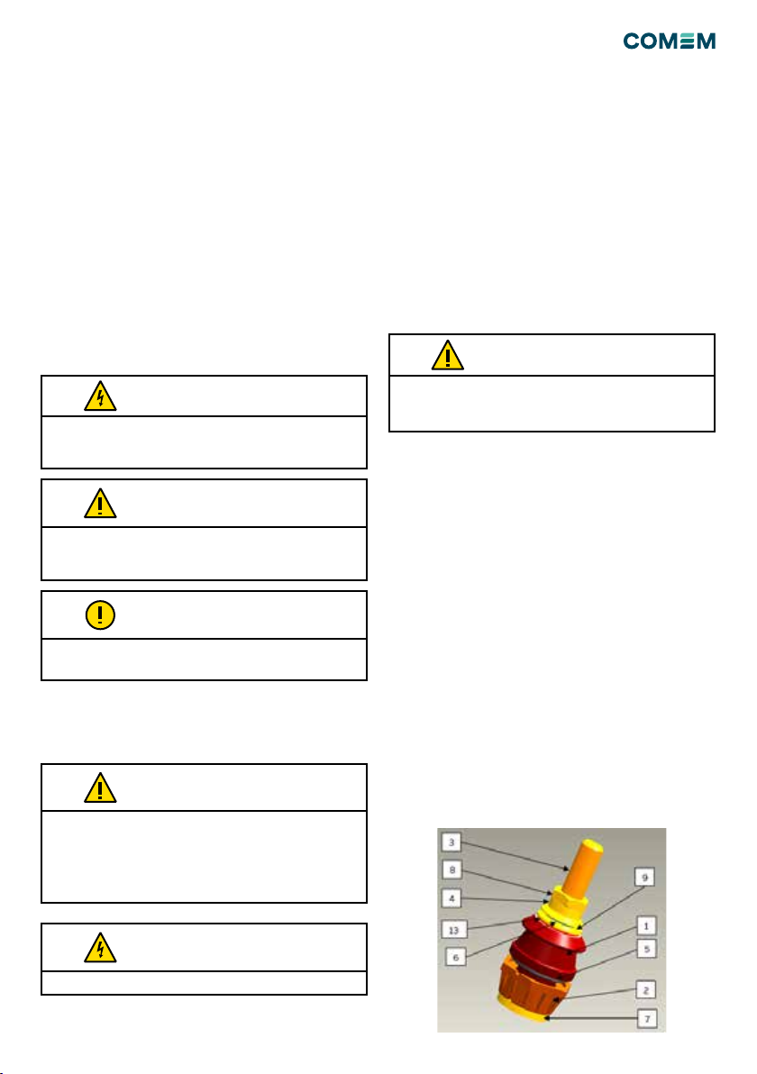
Figure 1
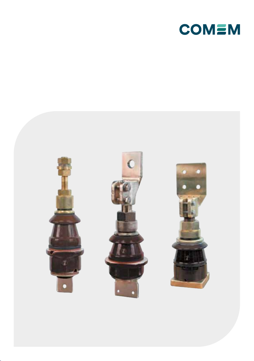
PORCELAIN BUSHINGS LOW VOLTAGE
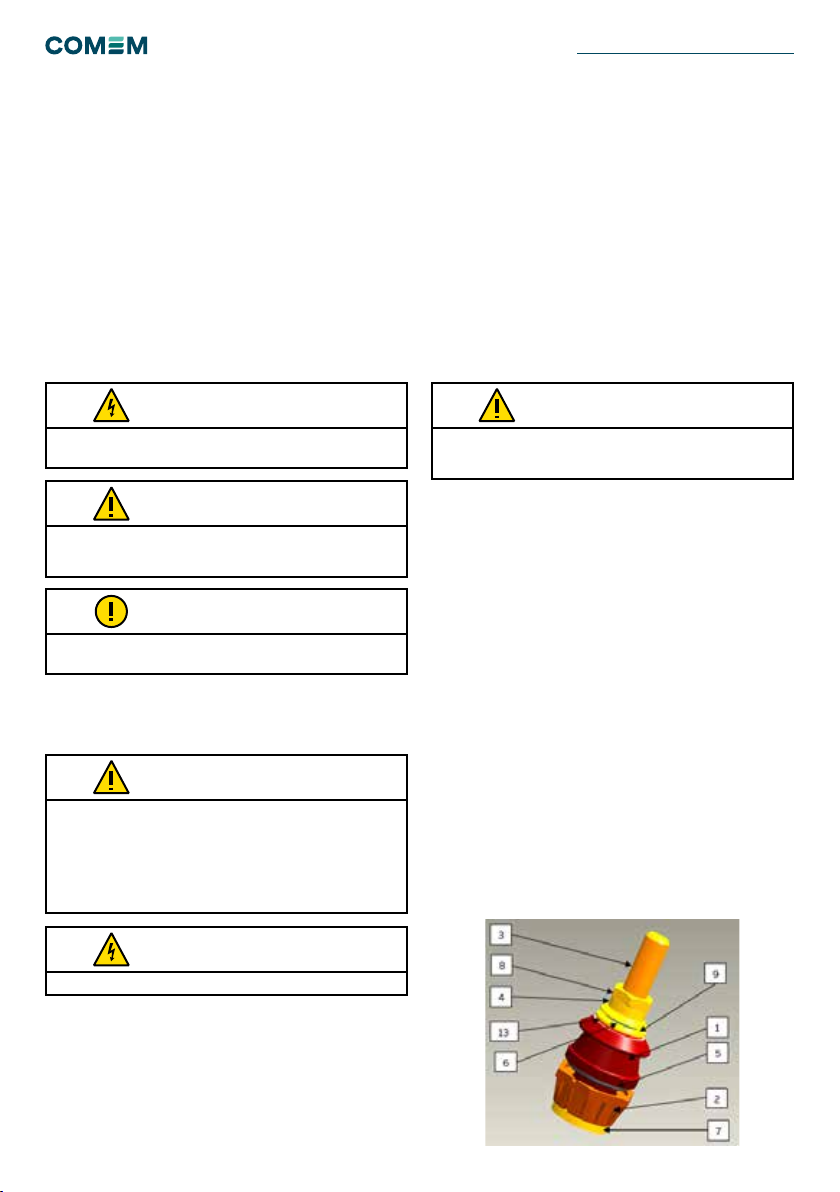
The porcelain insulator bushing (gure 1) must be installed
using the following steps:
• Check the thickness of tank which should correspond
with the value reported in each porcelain bushing
drawings; if the thickness is more than the reported
values, the oil will not ll the insulator properly.
• Make a hole on the tank of the transformer using the
diameters in table 18. If the porcelain bushing is
provided already assembled, Unscrew the nut
(component n. 8 in gure 1) and then slip off the
porcelain (1) with the assembled gasket (5) and the
metal part and gaskets in air: 10,6,9,4 (gure 1).
• The bolt (3) with soldered lower washer (7) must be
installed as pictures in picture 1 (the lower insulation (2)
ensemble with the bolt), through the hole on the tank
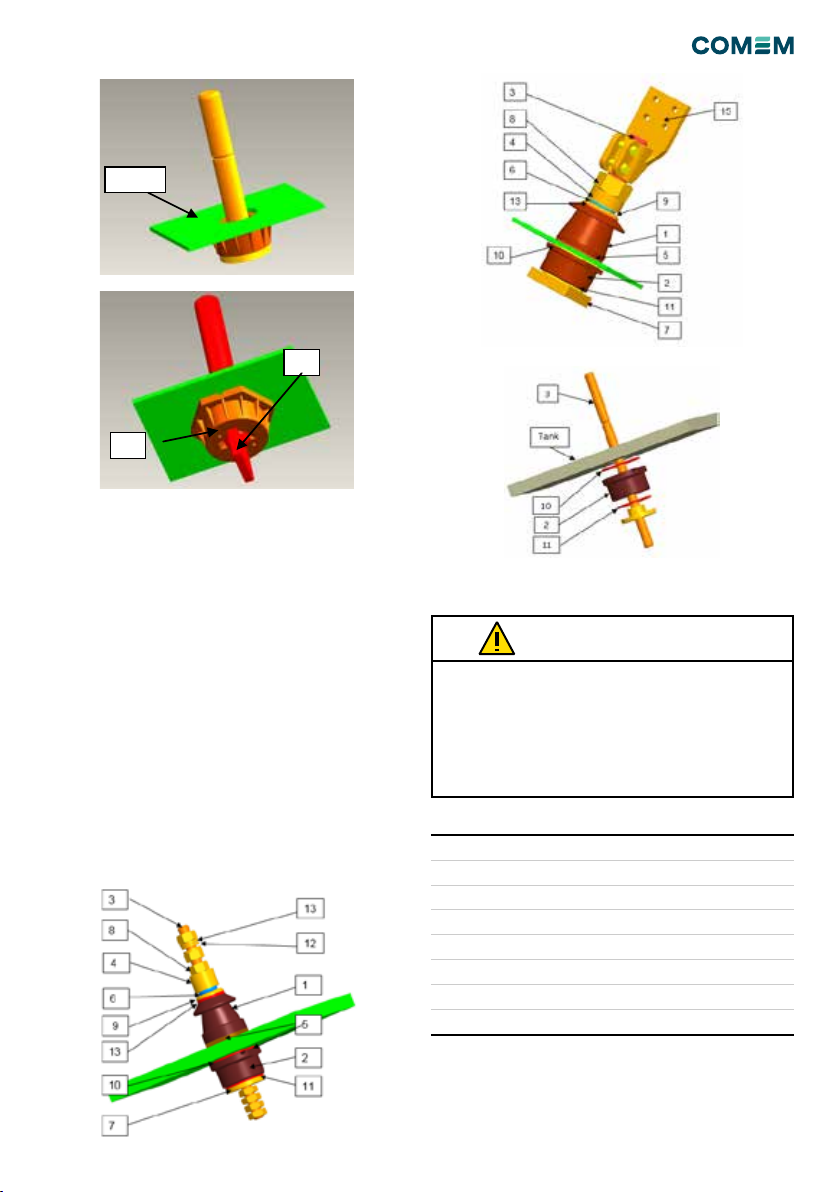
• If the insulator bushing correspond to solution “B “the
bolt plate Y has to be place in the plate housing X (gure 3)
• Assembly the components: (5), (1), (10), (6), (9) ,(4), (8)
and once the insulator bushing is full of oil, the air inside
must be removed unscrewing the nut (8) and nally the
rated torque shall be applied to the upper nut (see table
18).