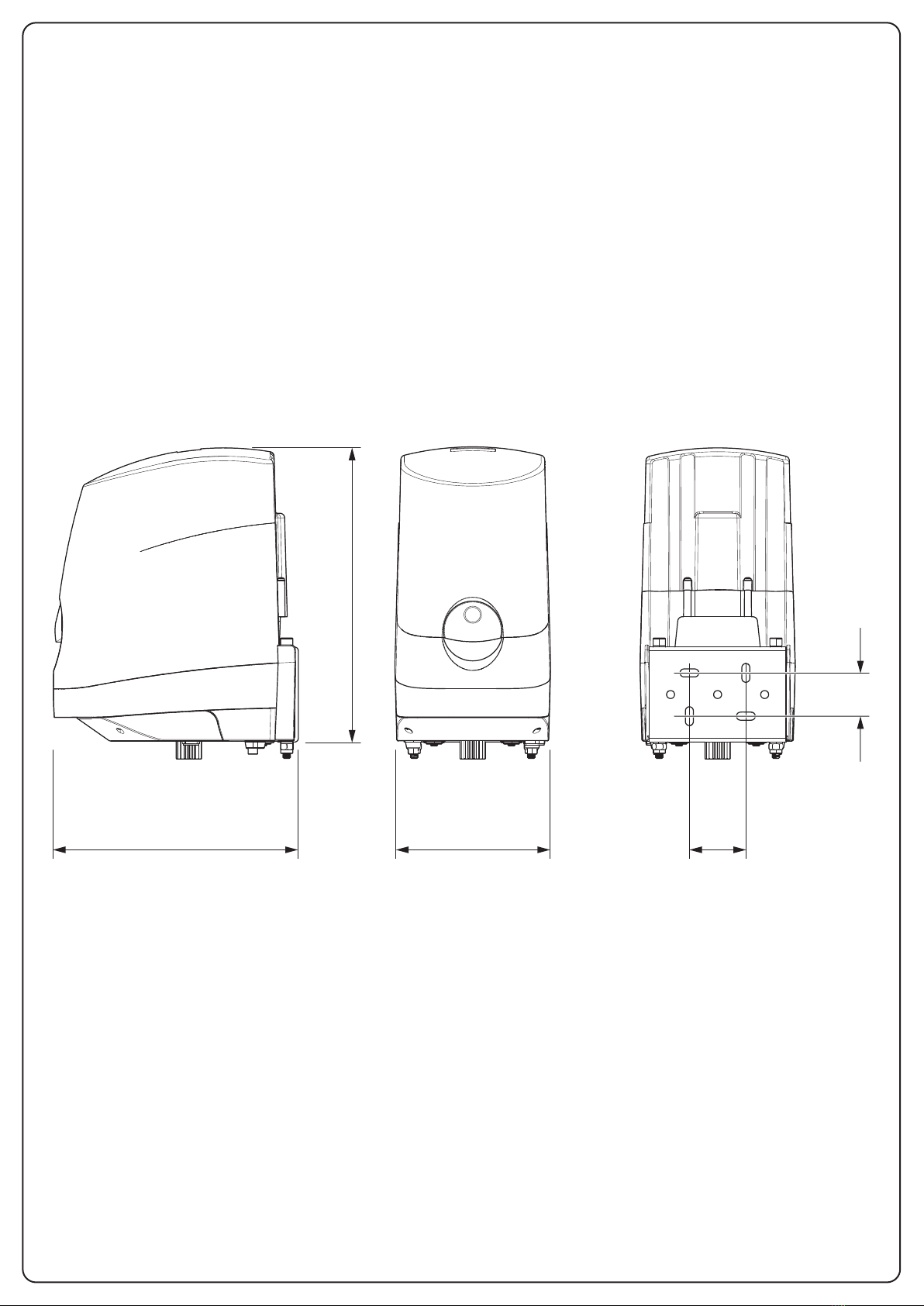
V2 ZORUS User manual

ZIS510
IL 341-1
EDIZ. 12/12/2019
ZORUS
GB
IRREVERSIBLE
ELECTROMECHANICAL PIVOTING
ARM ACTUATOR FOR SWING GATES

165
306
250 62
46

ENGLISH
- 35 -
INDEX
1 - GENERAL SAFETY INFORMATION ........................................................................................................................
1.1 - TECHNICAL ASSISTANCE SERVICE...................................................................................................................
1.2 - PRELIMINARY CHECKS and IDENTIFICATION OF THE TYPE TO BE USED ...........................................................
1.3 - EU DECLARATION OF CONFORMITY ...............................................................................................................
2 - TECHNICAL DATA ..................................................................................................................................................
USE LIMITATIONS ....................................................................................................................................................
3 - INSTALLATION OF THE MOTOR............................................................................................................................
3.1 - INSTALLATION LAYOUT ...................................................................................................................................
3.2 - INSTALLATION OF THE REAR FIXING BRACKET ................................................................................................
3.3 - SECURING THE GEAR MOTOR TO THE FIXING BRACKETS ...............................................................................
3.4 - INSTALLATION OF THE FRONT FIXING BRACKET ..............................................................................................
3.5 - INSTALLATION AND ADJUSTMENT OF THE MOTOR LIMIT SWITCHES...............................................................
3.6 - ELECTRICAL CONNECTIONS............................................................................................................................
4 - CONTROL UNIT......................................................................................................................................................
4.1 - ENERGY SAVING FUNCTION ...........................................................................................................................
4.2 - INSTALLATION.................................................................................................................................................
4.3 - CONNECTION OF THE MOTOR........................................................................................................................
4.4 - EXTERNAL PHOTOCELL CONNECTION.............................................................................................................
4.5 - INTERNAL PHOTOCELL CONNECTION .............................................................................................................
4.6 - CONNECTING SAFETY RIBBONS......................................................................................................................
4.7 - ACTIVATION INPUTS........................................................................................................................................
4.8 - STOP...............................................................................................................................................................
4.9 - LOW VOLTAGE LIGHT OUTPUT........................................................................................................................
4.10 - COURTESY LIGHTS........................................................................................................................................
4.11 - LOCK............................................................................................................................................................
4.12 - EXTERNAL AERIAL.........................................................................................................................................
4.13 - PLUG IN RECEIVER ........................................................................................................................................
4.14 - ADI INTERFACE .............................................................................................................................................
4.15 - POWER SUPPLY.............................................................................................................................................
4.16 - BATTERY POWER ..........................................................................................................................................
4.17 - ELECTRICAL CONNECTION SUMMARY .........................................................................................................
5 - CONTROL PANEL ...................................................................................................................................................
5.1 - DISPLAY..........................................................................................................................................................
5.2 - USE OF THE KEYS FOR PROGRAMMING..........................................................................................................
6 - INITIALISING THE CONTROL UNIT........................................................................................................................
7 - ACCESSING THE CONTROL UNIT SETTINGS.........................................................................................................
8 - RAPID CONFIGURATION .......................................................................................................................................
8.1 - POWER ADJUSTMENT.....................................................................................................................................
8.2 - OBSTACLE SENSOR ADJUSTMENT...................................................................................................................
8.3 - OPERATIONAL LOGIC......................................................................................................................................
8.4 - EXITING RAPID CONFIGURATION ....................................................................................................................
9 - LOADING THE DEFAULT PARAMETERS ................................................................................................................
10 - WORKING TIME SELF-TRAINING ........................................................................................................................
11 - READING OF CYCLE COUNTER ...........................................................................................................................
11.1 - SIGNAL OF SERVICE REQUIRED .....................................................................................................................
12 - PROGRAMMING THE CONTROL UNIT................................................................................................................
13 - OPERATION DEFECTS ..........................................................................................................................................
14 - TESTING AND START-UP......................................................................................................................................
15 - MAINTENANCE....................................................................................................................................................
16 - DISPOSAL.............................................................................................................................................................
36
37
38
38
38
38
39
39
40
41
41
42
42
44
44
44
44
45
45
45
46
46
46
46
47
47
47
47
47
47
48
49
49
50
50
52
52
53
53
54
54
55
56
57
57
58
64
66
66
66

ENGLISH
- 36 -
AUTOMATION DEVICE
INSTALLERS MANUAL
1 - GENERAL SAFETY INFORMATION
mPrior to proceeding with installation, it is essential the
instructions be read in full, since they contain important
information regarding safety, installation, use and
maintenance.
AUTOMATION MUST BE IMPLEMENTED IN COMPLIANCE WITH
THE EUROPEAN REGULATIONS IN FORCE:
EN 60204-1, EN 12445, EN 12453, EN 13241-1, EN 12635
• The installer must provide for a device (es. magnetotermical
switch) ensuring the omnipolar sectioning of the equipment
from the power supply. The standards require a separation of
the contacts of at least 3 mm in each pole (EN 60335-1).
• The plastic case has an IP44 insulation; to connect flexible or
rigid pipes, use pipefittings having the same insulation level.
• Installation requires mechanical and electrical skills, therefore it
shall be carried out by qualified personnel only, who can issue
the Compliance Certificate concerning the whole installation
(Machine Directive 2006/42/CEE, Annex IIA).
• Also the automation upstream electric system shall comply with
the laws and rules in force and be carried out workmanlike.
• We recommend to make use of an emergency button, to be
installed by the automation (connected to the control unit
STOP input) so that the gate may be immediately stopped in
case of danger.
• For correct installation of the system, we recommend following
the instructions issued by UNAC very carefully
• This instruction manual is only for qualified technicians, who
specialize in installations and automations.
• The contents of this instruction manual do not concern the end
user.
• Every programming and/or every maintenance service should
be done only by qualified technicians.
• Anything not expressly described in these instructions is
prohibited; unforeseen uses may be a source of danger to
people and property.
• Do not install the product in explosive environments and
atmospheres: the presence of inflammable gases or fumes is a
serious safety hazard.
• Do not make any modifications to any part of the automation
device, or the accessories connected to it, unless described in
this manual.
• Any other modifications will void the warranty on the product.
• The installation steps should be conducted so as to avoid rainy
weather, which can expose electronic circuits to dangerous
water seepage.
• All operations requiring the casing of the device to opened
should be performed with the control unit disconnected from
the electricity supply and with a warning notice displayed, for
example: ”CAUTION, MAINTENANCE IN PROGRESS”.
• Avoid exposing the device close to sources of heat and flame.
• In the event of interventions on automatic or differential
breakers or fuses, it is essential that faults be identified and
resolved prior to resetting. In the case of faults that cannot
be resolved using the information to be found in this manual,
consult the V2 customer assistance service.
• V2 declines all responsibility for failure to comply with good
construction practice standards in addition to structural
deformation of the gate that might occur during use.
• V2 reserves the right to make modifications to the product
without prior warning.
• Installation/maintenance personnel should wear individual
protection devices (IPDs), such as overalls, safety helmets, boots
and gloves.
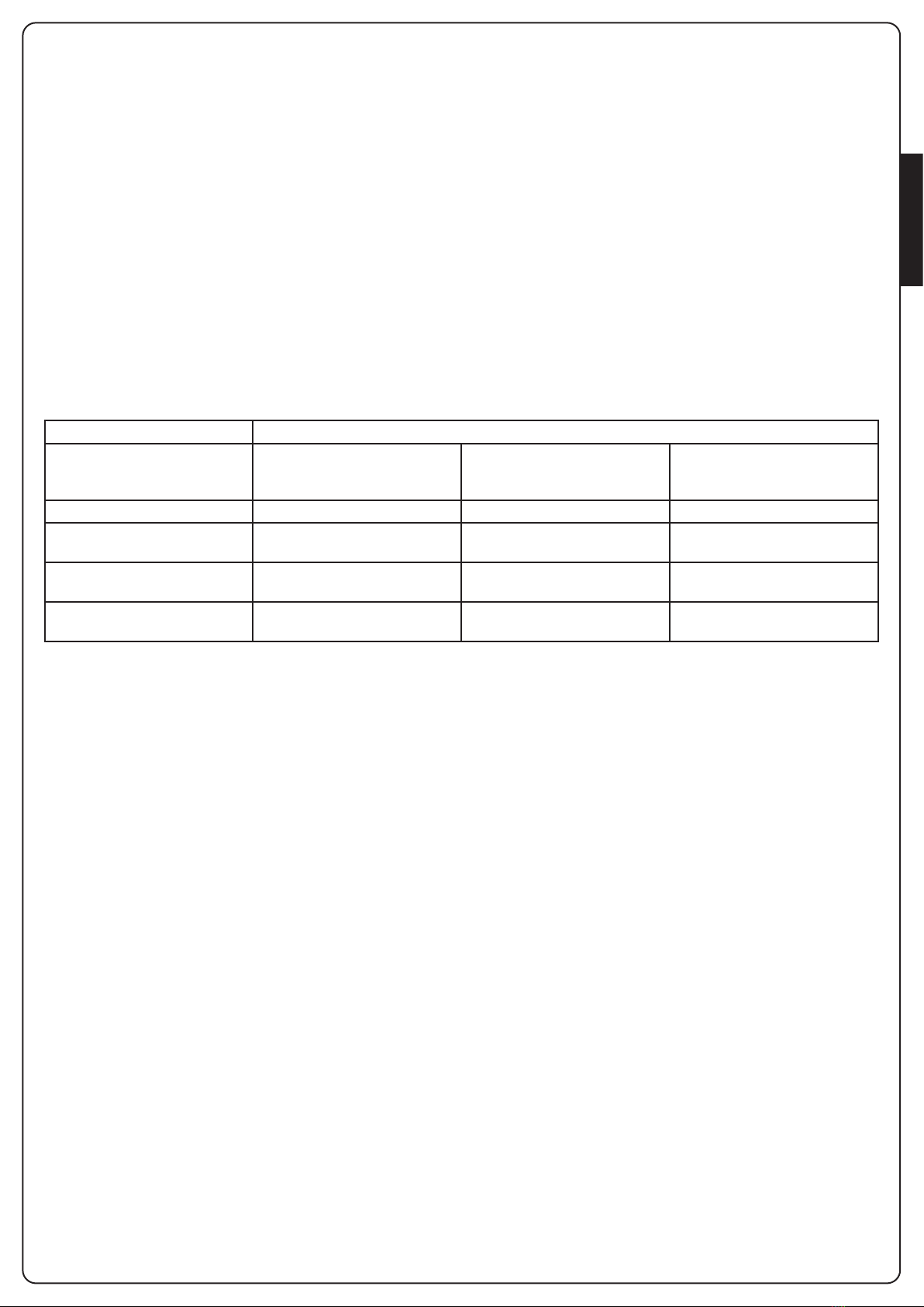
• The ambient operating temperature should be that indicated in
the technical characteristics table.
• The automation device should be shut down immediately in
the event of any anomalous or hazardous situation; the fault
or malfunction should be immediately reported to the person
responsible.
• All safety and hazard warnings on the machinery and
equipment should be complied with.
• Electromechanical actuators for gates are not intended to be
used by people (including children) with diminished physical,
sensory or mental capacity, or lacking in experience or
knowledge, unless they are under supervision or have been
instructed in use of the actuator by a person responsible for
safety.
• DO NOT introduce objects of any kind into the compartment
below the motor cover.
V2 has the right to modify the product without previous
notice; it also declines any responsibility to damage or
injury to people or things caused by improper use or wrong
installation.
1.1 - TECHNICAL ASSISTANCE SERVICE
For any installation problem please contact our Customer Service
at the number +39-0172.812411 operating Monday to Friday
from 8:30 to 12:30 and from 14:00 to 18:00.

ENGLISH
- 37 -
1.2 - PRELIMINARY CHECKS AND IDENTIFICATION OF THE TYPE TO BE USED
The automation device should not be used until installation, as specified in “Testing and start-up”, has been performed.
It should be remembered that the device does not compensate for defects caused by improper installation, or poor maintenance, thus, prior
to proceeding with installation, ensure that the structure is suitable and meets current standards and, if necessary, perform any structural
modifications aimed at the implementation of safety gaps and the protection or segregation of all crushing, shearing and transit zones, and
verify that:
• The gate has no friction points, either during closing or opening.
• The gate must be equipped with mechanical stoppers.
• The gate is well balanced, i.e. there is no tendency to move spontaneously when stopped in any position.
• The position identified for fixing the motor reducer allows easy and safe manual manoeuvring, compatible with the size of the motor
reducer itself.
• The support on which the automation device will be fixed is solid and durable.
• The mains power supply to which the automation device is connected has a dedicated safety earthing system and differential breaker
with tripping current less than or equal to 30 mA (the breaker gap distance should be greater than or equal to 3 mm).
Warning: The minimum safety level depends on the type of use; please refer to the following outline:
CLOSURE USE TYPE
TYPE OF ACTIVATION
COMMANDS
GROUP 1
Informed people
(use in private area)
GROUP 2
Informed people
(use in public area)
GROUP 3
Informed people
(unlimited use)
Man-present command A B Not possible
Remote control and closure in
view (e.g. infrared)
C or E C or E C and D or E
Remote control and closure not
in view (e.g. radio)
C or E C and D or E C and D or E
Automatic control
(e.g. timed closure control)
C and D or E C and D or E C and D or E
GROUP 1 -Only a limited number of people are authorised for use, and closure is not in a public area. Examples of this type are gates inside
business premises, where the sole users are employees, or a part of them who have been suitably informed.
GROUP 2 - Only a limited number of people are authorised for use, but in this case, closure is in a public area. An example of this may be a
company gate that accesses onto a public street, and which is only used by employees.
GROUP 3 - Anyone can use the automated closure, which is thus located on public land. For example the access gate to a supermarket or
an office, or a hospital.
PROTECTION A - Closure is activated by means of a control button with the person present, i.e. with maintained action.
PROTECTION B - With the person present, closure is activated by a command controlled by means of a key-switch or the like, in order to
prevent use by unauthorised persons.
PROTECTION C - Restricts the force of the leaf of the door or gate. I.e., in the case of the gate striking an obstacle, the impact force must
fall within a curve established by the regulations.
PROTECTION D - Devices, such as photocells, capable of detecting the presence of people or obstacles. They may be active on just one side
or on both sides of the door or gate.
PROTECTION E - Sensitive devices, such as footboards or immaterial barriers, capable of detecting the presence of a person, and installed in
such a way that the latter cannot be struck in any way by a moving leaf or panel. These devices should be active within the entire “danger
zone” of the gate. The Machinery Directive defines “Danger Zone” as any zone surrounding and/or near machinery where the presence of
an exposed person constitutes a risk to the health and safety of that person.
The risk analysis should take into consideration all danger zones for the automation device, which should be appropriately
protected and marked.
In a clearly visible area, apply a sign with information identifying the motorised door or gate.
The installer should provide the user with all the information relating to automatic operation, emergency opening and
maintenance of the motorised door or gate.

ENGLISH
- 38 -
1.3 - EU DECLARATION OF CONFORMITY
AND DECLARATION OF INCORPORATION OF
PARTLY COMPLETED MACHINE
Declaration in accordance with Directives: 2014/35/UE (LVD);
2014/30/UE (EMC); 2006/42/CE (MD) ANNEX II, PART B
The manufacturer V2 S.p.A., headquarters in Corso Principi di
Piemonte 65, 12035, Racconigi (CN), Italy
Under its sole responsibility hereby declares that:
the partly completed machinery model(s):
ZORUS2-S, ZORUS2-M, ZORUS4-S, ZORUS4-M
Description: electromechanical actuator for gates
• is intended to be installed on gates, to create a machine
according to the provisions of the Directive 2006/42/EC.
The machinery must not be put into service until the final
machinery into which it has to be incorporated has been
declared in conformity with the provisions of the Directive
2006/42/EC (annex II-A).
• is compliant with the applicable essential safety requirements
of the following Directives:
Machinery Directive 2006/42/EC (annex I, chapter 1)
Low Voltage Directive 2014/35/EU
Electromagnetic Compatibility Directive 2014/30/EU
Directive ROHS3 2015/863/EU
The relevant technical documentation is available at the national
authorities’ request after justifiable request to:
V2 S.p.A.
Corso Principi di Piemonte 65, 12035, Racconigi (CN), Italy
The person empowered to draw up the declaration and to provide
the technical documentation:
Sergio Biancheri
Legal representative of V2 S.p.A.
Racconigi, il 01/06/2019
ZORUS2-S ZORUS2-M ZORUS4-S ZORUS4-M
Power supply Vac / Hz 24 Vdc 230 - 50 24 Vdc 230 - 50
Maximum power (2 motors) W 280 350
Speed Rpm 1,5 1,5
Torque N m 650 760
Working temperature °C -20 ÷ +55 -20 ÷ +55
Working cycle % 80 80
Motor weight Kg 7,5 7,5 7,5 7,5
Protection IP 44
2 - TECHNICAL DATA
2.1 - USE LIMITATIONS
Before installing the product, check that the size and the weight
of the gate leaf are within the limits stated in chart.
kg - Maximum gate leaf weight
mm - maximum gate leaf length
mWARNING! The single leaf must not exceed 4.2m in
length
100
200
300
400
500
500 1000 2000 35003000 40002500 45001500
(mm)
(kg)

ENGLISH
- 39 -
3 - INSTALLATION OF THE MOTOR
3.1 - INSTALLATION LAYOUT
1 3
5
4
A
B
2
C
D
E
LENGTH OF THE CABLE < 10 metres from 10 to 20 metres from 20 to 30 metres
Power supply 230V 3G x 1,5 mm23G x 1,5 mm23G x 2,5 mm2
SLAVE motor power supply 2G x 1,5 mm22G x 1,5 mm22G x 2,5 mm2
Photocells (TX) 2 x 0,5 mm22 x 0,5 mm22 x 0,5 mm2
Photocells (RX) 4 x 0,5 mm24 x 0,5 mm24 x 0,5 mm2
Key switch 2 x 0,5 mm22 x 0,5 mm22 x 0,5 mm2
Flashing light 2 x 1,5 mm22 x 1,5 mm22 x 1,5 mm2
Antenna (integrated into the flashing light) RG174 RG174 RG174
ECO-LOGIC (accumulator unit) 2 x 1,5 mm2- -
ECO-LOGIC (solar panel) 2 x 1 mm2- -
A
B
C
D
E
1
2
3
4
5
Key switch
Pillar photocells
Pillar-mounted digital radio switch
Safety edges
ECO-LOGIC
Motor
Transmitter
Receiving module
Photocells
Flashing light
COMPONENTS ADDITIONAL ACCESSORIES

ENGLISH
- 40 -
3.2 - INSTALLATION OF THE REAR FIXING
BRACKET
Calculate the rear bracket position using chart.
100
150
200
250
300
350
400
450
100 150 200 250 300 350
C
(mm)
A
(mm)
100°-110°
110°-120°
95°-100°
90°-95°
This chart is used to define distances A and C and the leaf
maximum opening angle.
A
max
398
C
162272
162271
max 655 mm
A C
140 30 90
250 30 110
140 80 90
185 80 100
140 130 90
170 130 95
140 160 90
160 160 95
140 200 90
150 200 90
140 240 90
150 240 90
140 280 90
170 280 90
140 320 90
170 320 90
162271
A C
140 30
250 30
140 80
190 80
140 130
170 130
140 160
160 160
140 200
160 200
162272
max 800 mm
90
120
90
100
90
100
90
95
90
95
min 14 mm
1
1
1
1. Measure value “C”, then trace a straight horizontal
line in chart 1 against the obtained valued. Select
a point in the line, taking into account the desired
opening angle, suitable for the column.
2. Trace a vertical line starting from the point identified
and obtain value A.
3. Before proceeding with the installation, make sure
that value A allows to fix the rear bracket, otherwise
select another point on the chart.
4. Finally, to fix the bracket on the leaf, refer to the
maximum dimensions of the arm.
Failure to comply with the bracket installation
distances may lead to automation operation faults,
such as:
- Cyclical movements and accelerations at some
positions of the stroke
- Increased motor noise
- Limited opening, or no opening at all (in case of
counter-lever fixed motor)
mWARNING! Before fixing the rear bracket, make
sure that the front bracket will be fixed to a solid
position of the gate leaf; the front bracket will have
to be secured at a different height than the rear
bracket.
5 mm
5. At this point, mark on the leaf and on the wall the
holes of the brackets which will then be used to fix
the two brackets
6. Fix the rear bracket of the motor to the wall
complying with the dimensions seen previously
Installation
examples

ENGLISH
- 41 -
3.3 - SECURING THE GEAR MOTOR TO THE
FIXING BRACKETS
Secure the gear motor to the rear bracket:
1. Secure the gear motor to the bracket using the screws,
washers and nuts supplied
2. Fully tighten the nuts to the screws
Install the arms onto the motor:
1. Secure the arm onto the gear motor using the screw
2. Fix the two arms to each other using the pin and the seger
Secure the gear motor to the front bracket:
1. Secure the gear motor arm to the bracket using the pin and
seger supplied
2. Tighten the seger fully onto the pin seat
3.4 - INSTALLATION OF THE FRONT FIXING
BRACKET
1. The front bracket must be secured to gate leaf
2. Define the front bracket position height
3. Fix the bracket to the solid section of the gate leaf

ENGLISH
- 42 -
3.5 - INSTALLATION AND ADJUSTMENT OF
THE MOTOR LIMIT SWITCHES
1. Release the gear motor
2. Remove the 2 screws underneath the motor and remove the
cover
3. Unscrew the screw in the motor arm and remove it
4. Fix the limit switches on the motor arm; these must also be
installed in the presence of mechanical stops on the ground
5. At this point re-install the arm onto the motor
6. Manually verify that, when opening and closing, the gate leaf
stops at the desired points
Opening
Closing
Closing
Opening

ENGLISH
- 43 -
3.6 - ELECTRICAL CONNECTIONS
mWARNING!
• An incorrect connection can cause faults or dangerous
situations; therefore, scrupulously comply with the
indicated connections.
• Perform the connection operations with the power
supply disconnected.
1. Remove the gear motor cover
A
C
B
2. Loosen the cable gland of the gear motor and insert the
connection cables
A
B
3. Bring the cables to the top of the motor near the control unit
4. To connect the two motors, refer to the part of the manual
relating to the “Control unit”
7. By screwing or unscrewing the two screws (A) on the motor,
the two limit switches can be adjusted; then, using the two
screws (B) block the two adjusting screws
A
A
B
B
8. Replace the cover and tighten the two screws
9. Finally, secure the gear motor by turning the release key
10. For the assembly of the second motor, carry out the same
operations proceeding in reverse order for the adjustment of
the limit switches
11. After installing and adjusting the motors, position the
leaves halfway along their stroke so that, after making the
electrical connections, they can learn the opening and closing
procedures correctly
Opening
Closing

ENGLISH
- 44 -
4 - CONTROL UNIT
PD12 is provided with a display that, not only makes
programming simple, but also allows a continuous monitoring of
the input statuses; in addition, thanks to a menu structure, the
working schedule and the operation logic can be set easily.
In compliance with the European standards concerning electrical
safety and electromagnetic compatibility (EN 60335-1, EN 50081-
1 and EN 50082-1) it has been equipped with the low voltage
circuit total electric insulation (motors included) from the network
voltage.
Other characteristics:
• Power supply protected from short circuits within the
controller, on the motors and on the connected accessories.
• Adjustment of the power by partializing the current.
• Detecting obstacles by monitoring the current on the motors
(current sensing probe)
• Automatic learning of the operation time
• Obstacle sensor: a system allowing detection of whether
movement of the gate is impeded by an obstacle.
This system is based on measurement of the current absorbed
by the motor: an unexpected increase in current absorption
indicates the presence of an obstacle.
• Tests for safety devices (photocells and safety ribbons) before
each opening.
• Deactivation of safety inputs through the configuration
menu: no jumper is required for terminals concerning safety
devices that have not been installed, yet. You will only need
to disable this function from its relevant menu.
• The device can operate without mains power, by using the
optional battery pack (code 161212).
• Low voltage output that can be used for a signal light or a
24V flashing light.
• Auxiliary relay with programmable logic for courtesy light,
flashing light or other use.
• ENERGY SAVING function
4.1 - ENERGY SAVING function
This function is useful for reducing the energy consumption of the
automation device while in stand-by mode.
If the function is enabled, the control unit will enter ENERGY
SAVING mode under the following conditions:
• 5 seconds after completion of an operational cycle
• 5 seconds after an opening (if automatic closure is not
enabled)
• 30 seconds after exiting the programming menu
In ENERGY SAVING mode, power to the accessories, display and
flashing lights is deactivated.
ENERGY SAVING mode is exited:
• If an operational cycle is activated
• If one of the menus is accessed
4.2 - INSTALLATION
Installation of control unit and safety devices must be carried out
with power disconnected.
4.3 - CONNECTION OF THE MOTOR
The control unit is supplied already connected to the MASTER
motor.
The SLAVE motor (if used) should be connected to terminals
K1 - K2 - K3, following the polarity indicated on the labels
attached to the control unit and the Slave motor itself.
K1
K2
K3
K4
K5
K6
K7
K8
K9
K10
J1
J2
J3
J4
J5
J6
J7
J8
J9
A1
A2
B1
B2
COURTESY
LIGHT
CONTACT
RECEIVER
LOCK
LAMP 24V-3W
+24VDC
COM (-)
+24VDC
(Photo TX / Edge Test)
START P.
STOP
COM
PHOTO
PHOTO-I
EDGE1
EDGE2
COM
BATTERY
+
START
ANT
M2
M1
Max 500mA
24 Vdc
POWER SUPPLY
24Vdc
24Vdc
Control unit model: PD12
24Vdc
M2
(SLAVE)
(MASTER)

ENGLISH
- 45 -
mPHOTOCELLS - INSTRUCTIONS
• The control unit powers the photocells at a nominal voltage
of 24 Vdc, with an electronic fuse that breaks the current in
the case of an overload.
• If the transmitter power supply is connected to terminals
K8 and K9, the control unit can perform the photocell
operation test prior to starting gate opening.
• The photocells on the interior side should be installed so as to
completely cover the gate opening area.
• If several pairs of photocells are installed on the same side of
the gate, the receiver N.C. outputs should be connected in
series.
• The photocells are not powered when the control unit is in
ENERGY SAVING mode.
4.4 - EXTERNAL PHOTOCELL CONNECTION
Photocells installed on the exterior side of the gate should be
connected as follows:
• Connect the transmitter power supply to terminals
K8 (+Test) and K9 (-)
• Connect the receiver power supply to terminals
K10 (+24 VDC) and K9 (-)
• Connect the receiver N.C. output to terminals
J5 (PHOTO) and J4 (COM)
K1
K2
K3
K4
K5
K6
K7
K8
K9
K10
J1
J2
J3
J4
J5
J6
J7
J8
J9
A1
A2
B1
B2
COURTESY
LIGHT
CONTACT
RECEIVER
LOCK
LAMP 24V-3W
+24VDC
COM (-)
+24VDC
(Photo TX / Edge Test)
START P.
STOP
COM
PHOTO
PHOTO-I
EDGE1
EDGE2
COM
BATTERY
+
START
ANT
M2
M1
Max 500mA
24 Vdc
POWER SUPPLY
24Vdc
24Vdc
Control unit model: PD12
Photocells thus connected are active during closure.
In the case of tripping the photocell, the control unit immediately
re-opens the gate (without waiting for disengagement).
4.5 - INTERNAL PHOTOCELL CONNECTION
Photocells installed on the interior side of the gate should be
connected as follows:
• Connect the transmitter power supply to terminals
K8 (+Test) and K9 (-)
• Connect the receiver power supply to terminals
K10 (+24 VDC) and K9 (-)
• Connect the receiver N.C. output to terminals
J6 (PHOTO) and J4 (COM)
K1
K2
K3
K4
K5
K6
K7
K8
K9
K10
J1
J2
J3
J4
J5
J6
J7
J8
J9
A1
A2
B1
B2
COURTESY
LIGHT
CONTACT
RECEIVER
LOCK
LAMP 24V-3W
+24VDC
COM (-)
+24VDC
(Photo TX / Edge Test)
START P.
STOP
COM
PHOTO
PHOTO-I
EDGE1
EDGE2
COM
BATTERY
+
START
ANT
M2
M1
Max 500mA
24 Vdc
POWER SUPPLY
24Vdc
24Vdc
Control unit model: PD12
Photocells thus connected are active both during opening and
during closing. In the case of the photocell tripping, the control
unit immediately stops the gate.
When the photocell is disengaged, the gate re-opens fully.
mSAFETY RIBBONS - INSTRUCTIONS
• If several edges, with normally closed contacts, are used, the
outputs should be connected in series.
• If several conductive rubber edges are used, the outputs
should be connected in cascade, and only the final edge
should be terminated on the nominal resistance.
• Active edges connected to the accessory power supply are
inactive when the control unit switches to ENERGY SAVING
mode.
• To meet the requirements of EN12978, it is necessary to
install conductive rubber sensitive edges; contact normally
closed sensitive edges should have a control unit that
constantly verifies their correct operation. If control units
with the option to conduct testing by interrupting the power
are used, connect the control unit power cables between
terminals
K9 (-) and K8 (+Test) on the PD12.
Otherwise, connect them between terminals
K10 (+) and K9 (-).
Testing the edges should be activated by means of the
Co.tE menu.
4.6 - CONNECTING SAFETY RIBBONS
The control unit considers two kinds of safety ribbons, depending
on the terminal to which they are connected:
• Type 1 (fixed): they are mounted on walls or on other fixed
obstacles that are approached by the gate doors during the
opening phase. When type 1 safety ribbons operate during
the gate opening phase, the control unit will close the doors
for
3 seconds, then it stands still; when type 1 safety ribbons
operate during the gate closing phase, the control unit will
stand still immediately. The direction of the gate at next
command of START or PEDESTRIAN START depends upon the
parameter STOP (it inverts or continues the motion).
If the input STOP is disabled, the command makes the motion
continue in the same direction.
• Type 2 (mobile): they are mounted to the door ends.
When type 2 safety ribbons operate during the gate opening
phase, the control unit will stand still immediately; when type
2 safety ribbons operate during the gate closing, the control
unit will open the doors for 3 seconds, then it will stand still.
The direction of the gate at next command of START or
PEDESTRIAN START depends upon the parameter STOP (it
inverts or continues the motion). If the input STOP is disabled,
the command makes the motion continue in the same
direction.
Both the input can manage the classic safety edge with n.c.
contact and the conductive rubber safety edge with 8,2 kohm
nominal resistance.
Connect type 1 safety ribbons cables between terminals
J7 (EDGE1) and J9 (COM) of the control unit.
Connect type 2 safety ribbons cables between terminals
J8 (EDGE2) and J9 (COM) of the control unit.
K1
K2
K3
K4
K5
K6
K7
K8
K9
K10
J1
J2
J3
J4
J5
J6
J7
J8
J9
A1
A2
B1
B2
COURTESY
LIGHT
CONTACT
RECEIVER
LOCK
LAMP 24V-3W
+24VDC
COM (-)
+24VDC
(Photo TX / Edge Test)
START P.
STOP
COM
PHOTO
PHOTO-I
EDGE1
EDGE2
COM
BATTERY
+
START
ANT
M2
M1
Max 500mA
24 Vdc
POWER SUPPLY
24Vdc
24Vdc
Control unit model: PD12

ENGLISH
- 46 -
4.7 - ACTIVATION INPUTS
(START and START P.)
PD12 control unit is equipped with two activation inputs, whose
operation depends on the programmed operation modes
(see Strt item of programming menu):
• Standard mode
START = START (a command will cause the complete
opening of the gate)
START P. = PEDESTRIAN START (a command will cause the
partial opening of the gate)
• Open/Close command
START = OPENING (always controls the gate opening)
START P. = CLOSING (always controls the gate closing)
This is an impulse command, that is to say that an impulse
will cause the complete gate opening or closing.
• Manned operation
START = OPENING (always controls the gate opening)
START P. = CLOSING (always controls the gate closing)
This is a monostable command, that is to say, the gate will
be opened or closed as long as the contact is closed and it
will immediately stop as the contact is open
• Timer mode
This function allows programming the gate opening time
during the day, by making use of an external timer.
START = START (a command will cause the complete
opening of the gate)
START P. = PEDESTRIAN START (a command will cause the
partial opening of the gate)
The gate stays open (completely or partially) while the contact
is closed on input; as soon as the contact is open the pause
time count down will start, after which the gate will be
closed again.
ATTENTION: Automatic closing must be enabled
In all modes, inputs must be connected to devices having
normally open contacts.
Connect cables of device controlling the first input between
terminals J1 (START) and J4 (COM) of the control unit.
Connect cables of device controlling the second input between
terminals J2 (START P.) and J4 (COM) of the control unit.
K1
K2
K3
K4
K5
K6
K7
K8
K9
K10
J1
J2
J3
J4
J5
J6
J7
J8
J9
A1
A2
B1
B2
COURTESY
LIGHT
CONTACT
RECEIVER
LOCK
LAMP 24V-3W
+24VDC
COM (-)
+24VDC
(Photo TX / Edge Test)
START P.
STOP
COM
PHOTO
PHOTO-I
EDGE1
EDGE2
COM
BATTERY
+
START
ANT
M2
M1
Max 500mA
24 Vdc
POWER SUPPLY
24Vdc
24Vdc
Control unit model: PD12
The first input function can also be activated by pressing hkey
outside the programming menu or by means of a remote control
stored on channel 1 (see relevant instructions of MR2 receiver).
The second input function can also be activated by pressing ikey
outside the programming menu or by means of a remote control
stored on channel 2.
4.8 - STOP
For a better safety, you can fit a stop switch that will cause the
immediate gate stop when activated. This switch must have
a normally close contact (NC) that will get open in case of
operation.
In case the STOP switch is operated while the gate is open, the
automatic closing function will always be disabled. To close the
gate again, you will need a start command (if the start function in
pause is disabled, it will be temporarily enabled to allow the gate
release).
Connect the stop switch cables between terminal
J3 (STOP) and J4 (COM) of the control unit.
K1
K2
K3
K4
K5
K6
K7
K8
K9
K10
J1
J2
J3
J4
J5
J6
J7
J8
J9
A1
A2
B1
B2
COURTESY
LIGHT
CONTACT
RECEIVER
LOCK
LAMP 24V-3W
+24VDC
COM (-)
+24VDC
(Photo TX / Edge Test)
START P.
STOP
COM
PHOTO
PHOTO-I
EDGE1
EDGE2
COM
BATTERY
+
START
ANT
M2
M1
Max 500mA
24 Vdc
POWER SUPPLY
24Vdc
24Vdc
Control unit model: PD12
The stop switch function can be activated by means of a remote
control stored on channel 3 (see relevant instructions of MR2
receiver).
4.9 - LOW VOLTAGE LIGHT OUTPUT
The PD12 control unit has a 24 VDC output that allows
connection of a maximum load of 3 W.
This output can be used to connect a warning light, indicating the
status of the gate, or for a low voltage flashing light.
Connect the low voltage signal light or flashing light wires to
terminals K7 (+) and K6 (-).
K1
K2
K3
K4
K5
K6
K7
K8
K9
K10
J1
J2
J3
J4
J5
J6
J7
J8
J9
A1
A2
B1
B2
COURTESY
LIGHT
CONTACT
RECEIVER
LOCK
LAMP 24V-3W
+24VDC
COM (-)
+24VDC
(Photo TX / Edge Test)
START P.
STOP
COM
PHOTO
PHOTO-I
EDGE1
EDGE2
COM
BATTERY
+
START
ANT
M2
M1
Max 500mA
24 Vdc
POWER SUPPLY
24Vdc
24Vdc
Control unit model: PD12
CAUTION: Pay attention to the polarity of the connected
device if necessary.
4.10 - COURTESY LIGHTS
Thanks to the output COURTESY LIGHT the control unit allows
the connection of an electric appliance (e.g. courtesy light or
garden lights), controlled automatically or by means of the special
transmitter key.
The courtesy light terminals can be alternatively used for a 230V
flashing light with integrated flasher.
The output COURTESY LIGHT is a simple N.O. contact with no
power supply.
Connect the cables to terminals B1 and B2.
K1
K2
K3
K4
K5
K6
K7
K8
K9
K10
J1
J2
J3
J4
J5
J6
J7
J8
J9
A1
A2
B1
B2
COURTESY
LIGHT
CONTACT
RECEIVER
LOCK
LAMP 24V-3W
+24VDC
COM (-)
+24VDC
(Photo TX / Edge Test)
START P.
STOP
COM
PHOTO
PHOTO-I
EDGE1
EDGE2
COM
BATTERY
+
START
ANT
M2
M1
Max 500mA
24 Vdc
POWER SUPPLY
24Vdc
24Vdc
Control unit model: PD12
N
L

ENGLISH
- 47 -
4.11 - LOCK
An electric lock can be assembled on the gate, to ensure a good
closing of doors. Make use of a 12V lock.
Connect lock cables to terminals K4 and K5 of the control unit.
K1
K2
K3
K4
K5
K6
K7
K8
K9
K10
J1
J2
J3
J4
J5
J6
J7
J8
J9
A1
A2
B1
B2
COURTESY
LIGHT
CONTACT
RECEIVER
LOCK
LAMP 24V-3W
+24VDC
COM (-)
+24VDC
(Photo TX / Edge Test)
START P.
STOP
COM
PHOTO
PHOTO-I
EDGE1
EDGE2
COM
BATTERY
+
START
ANT
M2
M1
Max 500mA
24 Vdc
POWER SUPPLY
24Vdc
24Vdc
Control unit model: PD12
4.12 - EXTERNAL AERIAL
We suggest to use the external aerial (model: ANS433) in order to
guarantee the maximal range.
Connect the antenna hot pole to terminal A2 (ANT) of the
control unit and the braiding to terminal A1 (ANT-).
NOTE: using the LUMOS flashing light with built-in antenna,
connect the terminal 3of the flashing light to the terminal
A2 (ANT) of the control unit and the terminal 4of the flashing
light to the terminal A1 (ANT-) of the control unit PD12
K1
K2
K3
K4
K5
K6
K7
K8
K9
K10
J1
J2
J3
J4
J5
J6
J7
J8
J9
A1
A2
B1
B2
COURTESY
LIGHT
CONTACT
RECEIVER
LOCK
LAMP 24V-3W
+24VDC
COM (-)
+24VDC
(Photo TX / Edge Test)
START P.
STOP
COM
PHOTO
PHOTO-I
EDGE1
EDGE2
COM
BATTERY
+
START
ANT
M2
M1
Max 500mA
24 Vdc
POWER SUPPLY
24Vdc
24Vdc
Control unit model: PD12
4.13 - PLUG IN RECEIVER
PD12 control unit is suitable for plugging in a MR2 receiver having
a high-sensitivity super-heterodyne architecture.
mWARNING: it is necessary to turn off the control unit
power before doing the operations mentioned here below.
Pay attention to the way you connect the removable
modules.
MR2 module receiver is provided with 4 channels and each of
them is suitable for a command of PD12 control unit:
• CHANNEL 1 gSTART
• CHANNEL 2 gPEDESTRIAN START
• CHANNEL 3 gSTOP
• CHANNEL 4 gCOURTESY LIGHT
NOTE: Before programming 4 channels and function
logics read carefully the instructions of MR2.
4.14 - ADI INTERFACE
The ADI (Additional Devices Interface) interface of the control unit
PD12 allows the connection to V2 optional modules.
Refer to V2 catalogue or to the technical sheets to see which
optional modules with ADI interface are available for this control
unit.
NOTE Please read the instructions of each single module to
install the optional modules.
4.15 - POWER SUPPLY
The control unit must be fed by a 230V 50Hz electric line,
protected by a differential magnetothermal switch complying with
the law provisions in force.
Connect the power supply wires to terminals L and N on the
board located next to the transformer.
Connect the earth cable to terminal
Fuse: 5A
L N
4.16 - BATTERY POWER
In the case of an electricity black-out, the device may be powered
using a battery pack (accessory code 161212).
The battery pack should be housed in the specific seating, as
shown in the figure.
Connect the battery pack connecter to the BATTERY terminals on
the control unit.
K1
K2
K3
K4
K5
K6
K7
K8
K9
K10
J1
J2
J3
J4
J5
J6
J7
J8
J9
A1
A2
B1
B2
COURTESY
LIGHT
CONTACT
RECEIVER
LOCK
LAMP 24V-3W
+24VDC
COM (-)
+24VDC
(Photo TX / Edge Test)
START P.
STOP
COM
PHOTO
PHOTO-I
EDGE1
EDGE2
COM
BATTERY
+
START
ANT
M2
M1
Max 500mA
24 Vdc
POWER SUPPLY
24Vdc
24Vdc
Control unit model: PD12

ENGLISH
- 48 -
4.17 - ELECTRICAL CONNECTION SUMMARY
K1
K2
K3
K4
K5
K6
K7
K8
K9
K10
J1
J2
J3
J4
J5
J6
J7
J8
J9
A1
A2
B1
B2
Fuse: T1.6A
230V-50Hz
L N
COURTESY
LIGHT
CONTACT
RECEIVER
LOCK
LAMP 24V-3W
+24VDC
COM (-)
+24VDC
(Photo TX / Edge Test)
START P.
STOP
COM
PHOTO
PHOTO-I
EDGE1
EDGE2
COM
BATTERY
+
START
ANT
M2
M1
Max 500mA
24 Vdc
POWER SUPPLY
24Vdc
24Vdc
Control unit model: PD12
ANT
Phase power supply 230Vac
Earth
Neutral power supply 230Vac

ENGLISH
- 49 -
B1 - B2 230Vac courtesy or flashing lights
K1 Motor 2 (+)
K2 Motor 2 (ground)
K3 Motor 2 (-)
K4 - K5 12V electrolock
K6 - K7 24V courtesy or flashing lights
K8 +24Vdc supply - photocell/optical edge TX for
functional Test
K9 Accessory power common (-)
K10 +24Vdc supply for photocells and other
accessories
J1 START - Open command for connecting
traditional devices with N.O. contact
J2 START P. - Pedestrian open command for
connecting traditional devices with N.O. contact
J3 STOP command. N.C. contact
J4 Common (-)
J5 Exterior photocell. N.C. contact
J6 Interior photocell. N.C. contact
J7 Type 1 edges (fixed). N.C. contact
J8 Type 2 edges (mobile). N.C. contact
J9 Accessories common (-)
A1 Antenna shield
A2 Antenna
BATTERY Battery pack (code 161212)
RECEIVER Connector for MR2 receiver
ADI Module interface
M1 Motor 1
24Vdc
Power Supply
Control unit power supply (+24 VDC)
OVERLOAD Signals an overload on the accessory power
supply
PLEASE NOTE: the highlighted connections are
factory pre-wired
5 - CONTROL PANEL
5.1 - DISPLAY
When power is on, the control unit checks that display correctly
operates by switching on all segments for 1.5 sec. 8.8.8.8.
Firmware version, e.g. Pr I.5, will be viewed in the following
1.5 sec.
Panel will be viewed upon completion of this test.
OPENING IN PROGRESS
OPENED CONTACTCLOSED CONTACT
START
PEDESTRIAN
START
PAUSE (GATE OPENED)
CLOSING IN PROGRESS
SAFETY RIBBON 2
OK
STOP
EXTERNAL
PHOTOCELL
INTERNAL
PHOTOCELL
SAFETY RIBBON 1
The control panel represents the physical status of the terminal
board contacts and of the program mode keys: if the upper
vertical segment is on, the contact is closed; if the lower vertical
segment is on, the contact is open (the above picture shows an
instance where the inputs PHOTO, PHOTO-I, EDGE and STOP have
all been correctly connected).
PLEASE NOTE: if the panel is off, the control unit should be
in ENERGY SAVING mode; press the OK key to turn it on.
Points being among display digits show the status of
programming push-buttons: as soon as a push-button is pressed,
its relevant point turns on.
The arrows on the left of the display show the state of the start
inputs. The arrows light when the related input is closed.
The arrows on the display right side show the gate status:
• The highest arrow turns on when the gate is into its opening
phase. If it blinks, it means that the opening has been caused
by a safety device (border or obstacle detector).
• The central arrow shows that the gate is on pause.
If it blinks, it means that the time countdown for the
automatic closing has been activated.
• The lowest arrow blinks when the gate is into its closing
phase. If it blinks, it means that the closing has been caused
by a safety device (border or obstacle detector).

ENGLISH
- 50 -
5.2 - USE OF THE KEYS FOR PROGRAMMING
The control unit functions and times are programmed by means
of a special configuration menu, which can be accessed and
explored by using the 3 keys, h, iand OK, located on the side of
the control unit display.
PLEASE NOTE: Outside the configuration menu, pressing
the hkey activates the START command, pressing the ikey
activates the PEDESTRIAN START command.
In the manual, the control unit programming procedure is
represented by block diagrams, consisting of the various display
views.
The various blocks include symbols showing the user the keys to
be pressed to navigate around the menu.
When a time is written to the side of the symbol, this means the
key should be pressed and held for the length of time indicated.
6 - INITIALISING THE CONTROL UNIT
This operation is necessary when the control unit is installed for
the first time, and is used to define the gate leaf starting order
and the direction of rotation of the two motors.
Until initialisation is performed, it is not possible to operate the
gate or program the control unit.
The initialisation procedure steps are as follows:
1. Starting initialisation
2. Selecting the superior and inferior gate leaves
3. Selecting the opening direction
4. Verifying Slave motor connection
5. Self-training the working times
mWARNING:
• Ensure that the motors and accessories are connected
correctly prior to performing initialisation
• Position the gate leaves roughly at the half way points
(unblock the motors, operate the gate leaves, re-block the
motors)
• Firstly, the procedure will involve short movements of the gate
leaves. In the final phase, the gate is moved through its entire
path. The operator should be positioned so as not to interfere
with the movement of the gate leaves and so as not to trip
any photocells
• Installation is automatically interrupted if no operations are
performed for one minute
• The initialisation procedure involves the loading of default
values for all programming menu parameters
The following table describes the functions of the push-buttons:
Press and release the push-button OK
Keep pressed the push-button OK for 2 seconds
Release the push-button OK
Press and release the push-button h
Press and release the push-button i
-ini Go
ESC
2’’
Start
Main screen
Press and hold OK for approx. 2 seconds, until the message “-ini” appears. On release of the key, the message GO appears.
Pressing OK starts the procedure. The arrow keys can be used to select “ESC”, thus exiting without starting the procedure.
Starting initialisation
The control unit moves the Master motor first in one direction,
then in the other, 3 times
Exit (initialisation incomplete)

ENGLISH
- 51 -
SUP
GO
inF
Ch1
AP1
AP2
Ch2 Er93
Er94
Er91
SinG
doP
?1
2
?3
4
t.LAu
Ft.no
Ft.S i
ESC
Select this parameter depending on the position (superior or inferior)
of the gate leaf in motion
SUP the gate leaf in motion is the leaf that should open first
inF the gate leaf in motion is the leaf that should open second
PLEASE NOTE: if installation envisages one motor only, select SUP
Select this parameter depending on the direction of opening of gate
leaf 1
AP1 the gate leaf is opening
Ch1 the gate leaf is closing
Having selected this parameter, the control unit moves the
SLAVE motor
1If the control unit detects the SLAVE motor, the display shows AP2
Select this parameter depending on the direction of opening of gate
leaf 2
AP2 the gate leaf is opening
Ch2 the gate leaf is closing
Having selected the parameter, press OK to move to the next phase.
If the display shows Er93, this means the SLAVE motor is connected
incorrectly.
Check the SLAVE motor connection and repeat the initialisation
procedure
2If the control unit does NOT detect the SLAVE motor,
the display shows SinG
If the installation envisages only one motor, press OK to move to the
next phase.
If the installation envisages two motors, select the doP menu option
and press OK.
The display will show Er94 to indicate that the SLAVE motor is not
connected, or is connected incorrectly.
Check the SLAVE motor connection and repeat the initialisation
procedure
3If the control unit does not detect a photocell on the PHOTO input,
the display shows Ft.no
If the installation does not envisage the use of a photocell, select
Ft.no and press OK to move to the next phase.
The photocell will be automatically disabled.
If installation envisages the use of a photocell, select Ft.Si and press
OK. The display will show Er91 to indicate that the photocell is not
connected, or is connected incorrectly.
Check the photocell connection and repeat the procedure.
4If the control unit detects a photocell connected correctly to the
PHOTO input, it automatically switches to the working time
self-training phase.
Press OK to start the self-training phase.
Select ESC and press OK to exit the menu without performing the
time self-training phase.
Please note: in the case of exiting without self-training, it will
not be possible to operate the gate.
In any case, it will be possible to perform self-training in a separate
phase and program the remainder of the control unit functions, using
the specific menu.

ENGLISH
- 52 -
7 - ACCESSING THE CONTROL
UNIT SETTINGS
Once initialisation is performed (even without time self-training),
it will be possible to access the various control unit functions,
including initialisation itself.
1. Press and hold the OK key until the display shows the menu
desired
2. Release the OK key: the display will show the first item in the
sub-menu
-CFG Rapid configuration
-PrG Programming the control unit (full menu)
-Cnt Cycle counter
-APP Self-training the working times
-dEF Loading the default parameters
-ini Control unit initialisation
8 - RAPID CONFIGURATION
Rapid configuration is a menu allowing the main control unit
parameters to be programmed with a few operations.
It is essential the initialisation procedure has already been
performed (even without time self-training) in order to perform
rapid configuration.
1. Press and hold the OK key until the display shows the -CFG
menu
2. Release the OK key: the display will show the first item in the
Pot menu.
Pot. Power adjustment
SEnS Obstacle sensor adjustment
LoG. Operation logic
FinE Exit the menu
-CFG Pot
-PrG En.SA
3’’
-Cnt tot
-APP ESC
-dEF ESC
-ini Go
----
6’’
9’’
12’
’
15’
’
18’
’
21’
’
Pot.
SEnS
LoG.
FinE
-CFG
Table of contents
Other V2 Gate Opener manuals